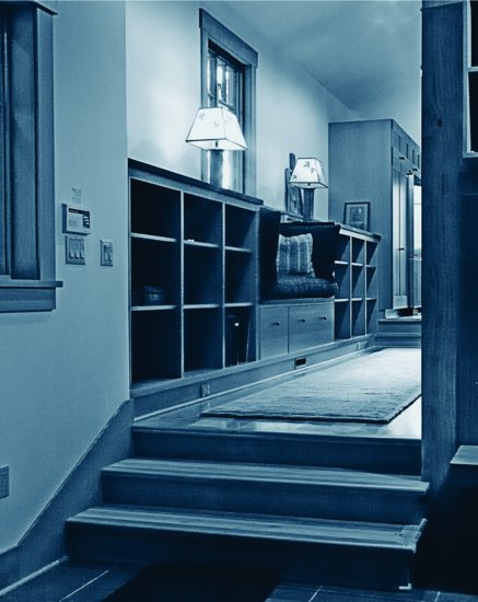
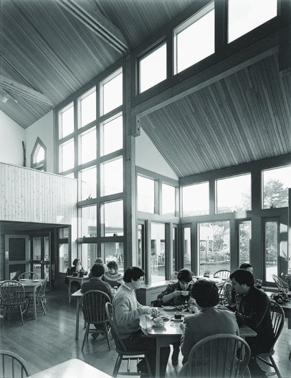
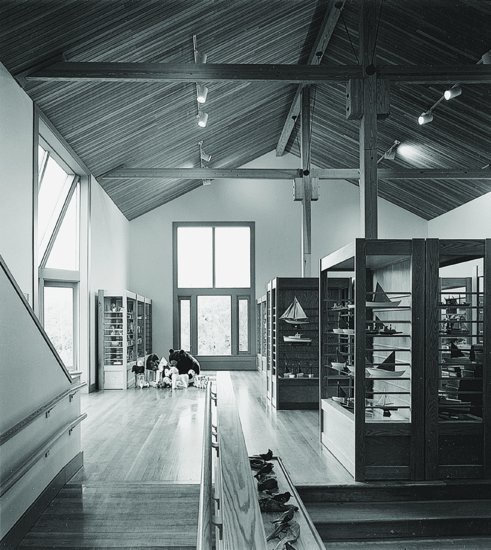
Architect Michael Craig Moore uses a rich palette of stone and wood contrasting with light-colored walls and ceiling surfaces. In the foreground is slate flooring. Stairs and wood floors are heartwood-only pine (“heart pine”). Wood cabinets and trim are vertical grain Douglas fir. Cabinet counters and the window seat top (middleground of the image) are a composite sheet material made from compressed paper and phenolic resin. Cabinet pulls are bronze. The exposed structural wood column, to the right in the image, is also Douglas fir. Wood surfaces are finished with clear polyurethane. Walls and ceilings are covered with gypsum wallboard finished with latex primer and topcoats. (Photograph by Michael Craig Moore, AIA.)
7
INTERIOR FINISHES FOR WOOD LIGHT FRAME CONSTRUCTION
Completing the Building Enclosure
Increasing Levels of Thermal Insulation
Miscellaneous Finish Carpentry
Flooring and Ceramic Tile Work
Figure 7.1 Insulated metal flue systems (shown here) are often more economical than masonry chimneys for furnaces, boilers, water heaters, package fireplaces, and solid-fuel stoves. (Photo courtesy of SELKIRK METALBESTOS.)
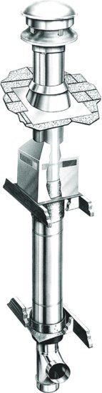
Figure 7.2 A mason adds a section of clay flue liner to a chimney. The large flue is for a fireplace, and the three smaller flues are for a furnace and two woodburning stoves. (Photo by Edward Allen.)
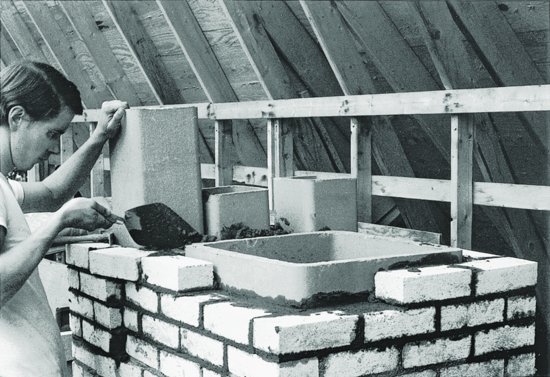
Figure 7.3 A typical residential wastewater system. All fixtures drain to the building drain through sloping or vertical branch lines. The waste pipe is vented to the exterior at each fixture through a network of vent pipes, shown with broken lines.
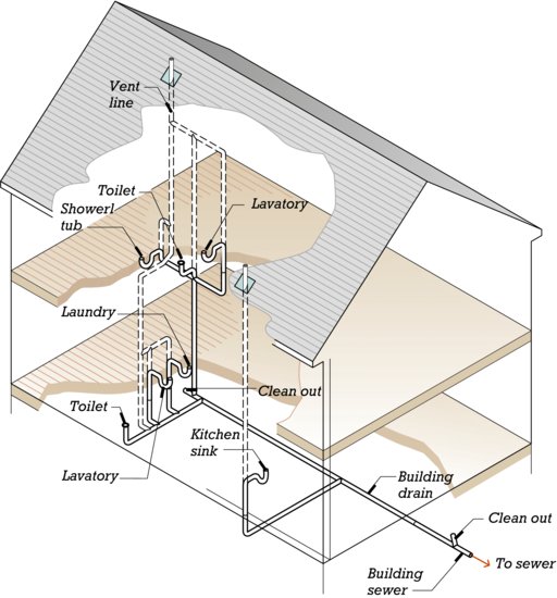
Figure 7.4 A typical residential water supply system. Water enters the house through a buried line and branches into two parallel sets of distribution lines. One is for cold water. The other passes through the water heater and supplies hot water.
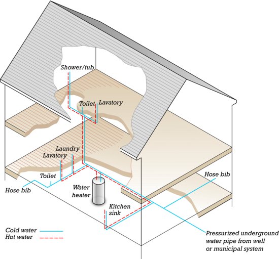
Figure 7.5 This plumbing wall is framed with 2 × 8 (38 × 184 mm) studs to provide adequate width for the plethora of building services routed within it, including: cast iron and plastic DWV piping, insulated hot water and bare cold water copper supply piping, refrigerant piping for a distributed air conditioning system, communications wiring, and power wiring. (Photo by Joseph Iano.)
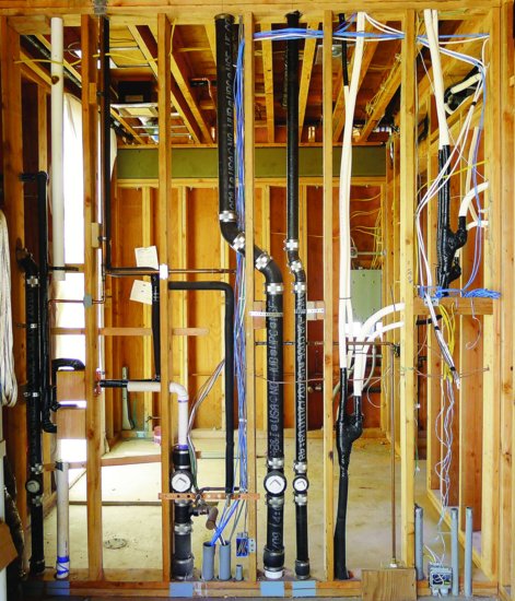
Figure 7.6 The plumber's work is easier and less expensive if the building is designed to easily accommodate piping. The “stacked” arrangement shown here, in which a second-floor bathroom and a back-to-back kitchen and bath on the first floor share the same vertical runs of pipe, is economical and easy to rough in, compared with plumbing that does not align vertically from one floor to the next. The double wall framing on the second floor allows plenty of space for the waste, vent, and supply pipes. The second-floor joists are located to provide a slot through which the pipes can pass at the base of the double wall, and the joists beneath the water closet (toilet) are headed off to house its waste pipe. The first floor shows an alternative type of wall framing using a single layer of deeper studs, which must be drilled to permit horizontal runs of pipe to pass through, as in Figure 7.5.
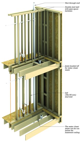
Figure 7.7 A forced-air system in a two-story building with a basement. The furnace is in the basement. It burns gas or oil, or uses electric resistance heating to warm a heat exchanger that creates warm air. It blows the warm air through sheet metal supply ducts to registers in the floor near the exterior walls. The air returns to the furnace through a centrally located return air duct that has a return air grill near the ceiling on each floor. With the addition of a heat pump or air conditioner, this system can deliver cool, dehumidified air during the warm months.
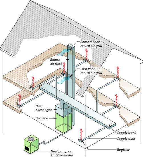
Figure 7.8 The installation of this hot air furnace and air conditioning unit is almost complete, needing only electrical connections. The metal pipe running diagonally to the left carries the exhaust gases from the oil burner to the masonry chimney. The ductwork is insulated to prevent moisture from condensing on it during the cooling season and to prevent excessive losses of energy from the ducts. (Photo by Edward Allen.)
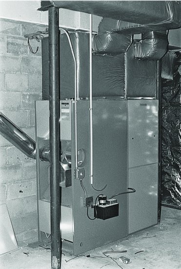
Figure 7.9 Ductwork and electrical wiring are installed conveniently through the openings in these floor trusses, making it easy to apply a finish ceiling if desired. The 2 × 6 that runs through the trusses in the center of the photograph is a bridging member that restrains the trusses from buckling. (Courtesy of Trus Joist Corporation.)
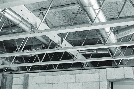
Figure 7.10 A hydronic heating system. The boiler burns gas or oil, or uses electric resistance heating to heat water. Pumps circulate the water through pipes that lead to convectors in various zones of the building. Inside each convector, a pipe heats closely spaced metal fins that warm the air in the room. The sheet metal convector covers are shown schematically and have been cut away in this drawing to reveal the metal fins.
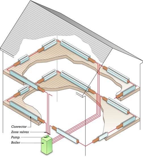
Figure 7.11 The radiant heating system in this two-story building delivers heat through hydronic tubes that warm the floors. There are four zones, two upstairs and two downstairs. Water is heated in a boiler and pumped through a supply manifold, where thermostatically controlled valves control the water flow to each of the zones.
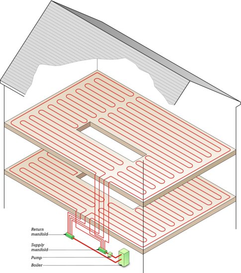
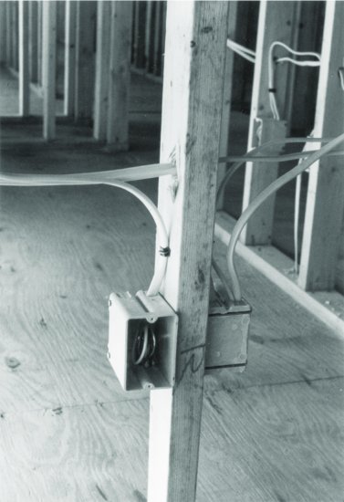
Figure 7.12 The electrician begins work by nailing plastic fixture boxes to the framing of the building in the locations shown on the electrical plan. Then holes are drilled through the framing, and the plastic-sheathed cable, which houses two insulated copper conductors and an uninsulated ground wire, is pulled through the holes and into the boxes, where it is held by insulated staples driven into the wood. After the interior wall materials are in place, the electrician returns to connect outlets, lighting fixtures, and switches to the wires and the boxes and to affix cover plates to finish the installation. (Photo by Edward Allen.)
COMPLETING THE BUILDING ENCLOSURE
The walls, roofs, and other surfaces of a building that separate the indoors from the outdoors may be referred to as the building envelope or building enclosure. The building enclosure controls the flow of heat, air, and moisture between the interior and exterior. Well-designed and carefully constructed enclosure assemblies help keep a building cooler in summer and warmer in winter by retarding the passage of heat and air through the exterior surfaces of the building. They help keep the occupants of the building more comfortable by moderating the temperatures of the interior surfaces of the building and reducing convective drafts. They reduce the building energy consumption for heating and cooling to a fraction of what it otherwise would be. Furthermore, they prevent the harmful accumulation of condensation within the exterior walls, roof, and other enclosure assemblies of the building.
Insulating the Building Frame
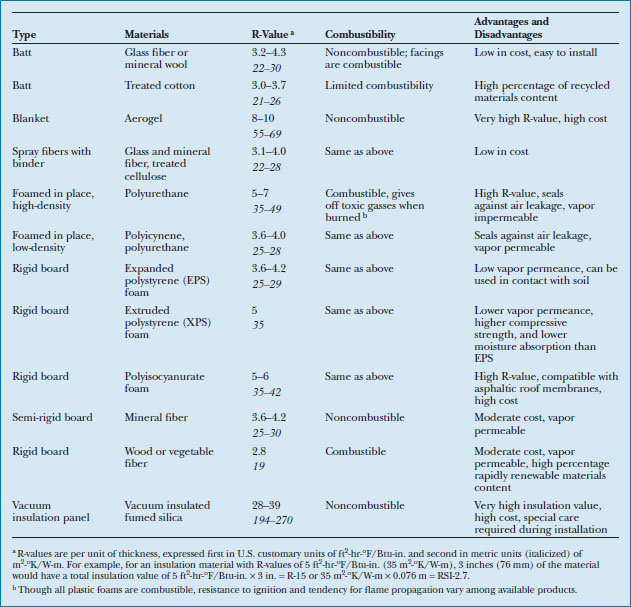
Thermal insulating materials resist the conduction of heat. Thermal insulation is added to virtually all buildings to limit winter heat loss and/or summer cooling loads. A material's resistance to the conduction of heat is measured as thermal resistance, abbreviated as R-value, or, in metric units, as RSI-value (or in many cases, also simply as R-value). A material with a higher R-value is a better insulator than one with a lower R-value. Figure 7.13 lists common thermal insulating materials used in wood light frame buildings and some of their characteristics. Glass fiber batts are the most popular, but all of those listed find use. For a more in-depth discussion of the role of thermal insulation in buildings, see Chapter 16.
Figure 7.13 Commonly used thermal insulation materials. The R-values offer a direct means of comparing the relative effectiveness of the different types of equal thickness. For more information about insulation materials used with low-slope roofing, see Chapter 16. You can download a PDF of this figure at http://www.wiley.com/go/aflblce6ne.
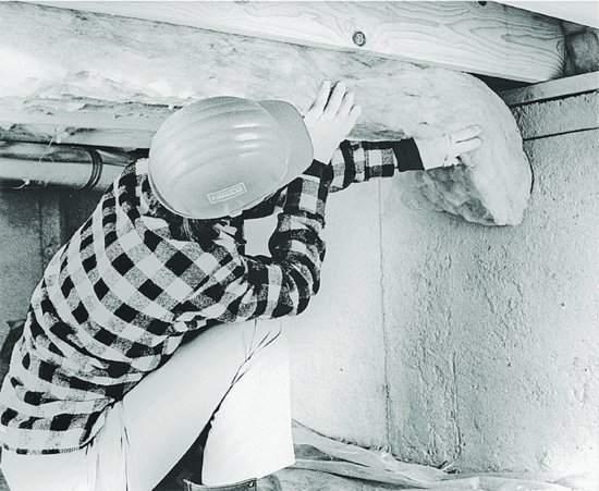
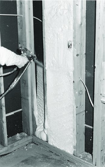
Batt insulation comes in 16 in. or 24 in. (406 or 610 mm) widths. It is installed by inserting the insulation between framing members and is held in place either by friction or, if the insulation has a paper or foil facing, by stapling the facing to the framing (Figure 7.14). Loose fill insulation is blown into attic floors or, in insulation retrofits, into wall cavities through holes drilled through the exterior siding. Spray fiber insulation is blown from a nozzle (Figure 7.15). A light spray of water activates a binder that adheres the insulation in place and prevents settlement. Foamed-in-place insulation usually consists of two components sprayed or injected into place, where they react chemically to expand and adhere to the surrounding surfaces (Figure 7.16). Rigid and semi-rigid board insulation are nailed in place over wood framing, or when used around foundations, adhered in place (Figure 5.12). Plastic foam insulation, both spray foam and rigid board, is combustible and releases toxic gasses when it burns. Where these materials face the building interior, most must be covered with gypsum wallboard or some other material that will delay the onset of combustion while occupants exit the building.
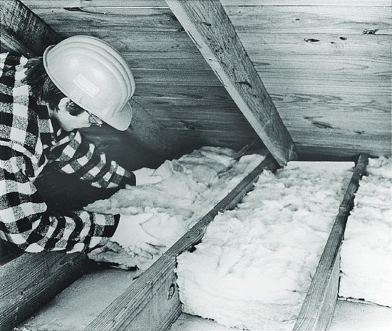
Figure 7.14 (a) Installing a polyethylene vapor retarder over glass fiber batt insulation using a staple hammer, which drives a staple each time it strikes a solid surface. The batts are unfaced and stay in place between the studs by friction. (b) Stapling paper-faced batts between roof trusses. (Better practice is to staple the paper facing to the face of the framing member rather than to its side as seen here.) (c) Placing unfaced batts between ceiling joists in an existing attic. Vent spacers should be used at the eaves (see Figure 6.7). (d ) Working from below to insulate a floor over a crawlspace. Batts in this type of installation may be retained in place by pieces of stiff wire cut slightly longer than the distance between joists and sprung into place at frequent intervals below the insulation. (e) Insulating crawlspace walls with batts of insulation suspended from the sill. The header space between the joist ends has already been insulated. (Courtesy of Owens-Corning Fiberglas Corporation.)
(a)
(b)

(c)
(d)
(e)
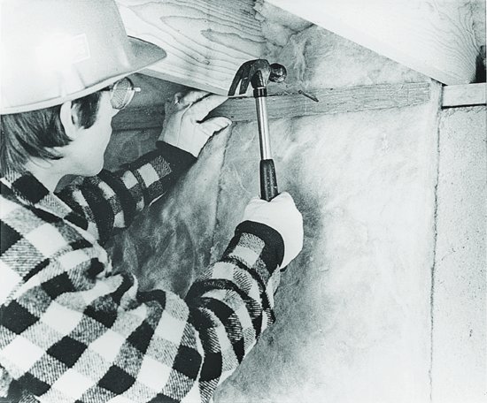
Figure 7.15 Blowing loose-fill glass fiber insulation into a ceiling below an attic. A vapor retarder was installed on the bottom side of the joists and then a gypsum board ceiling, which supports the insulation. Vent spacers were installed at the eaves to prevent the insulation from blocking eave vents. (Courtesy of Owens-Corning Fiberglas Corporation.)
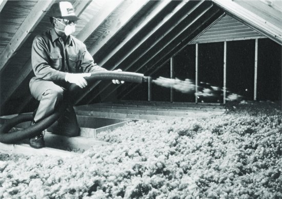
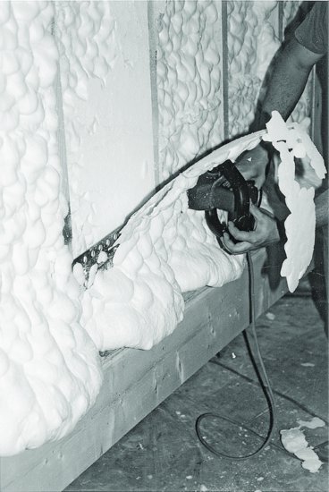
Figure 7.16 (a) Spraying a low-density polyicynene foam insulation between studs of a wood light frame building. At the time of spraying, the components are dense liquids, but they react immediately with one another to produce a low-density foam, as has already occurred at the bottom of the cavity. The foam in the cavity to the right has already been trimmed off flush with the studs. (b) Trimming off excess foam with a special power saw. (Courtesy of Icynene, Inc., Toronto, Canada.)
(a)
(b)
Aerogel insulation consists of a silica gel embedded in a flexible fabric. It is available in blanket form, approximately ¼ inch (6 mm) thick, suitable for both interior and exterior applications. It has a very high insulation value and is very costly. Vacuum insulated panels are made from rigid fumed silica boards that have been evacuated and then sealed within an airtight, vapor-tight foil or polymer wrapping. They are also very expensive, but have the highest available insulation values per unit of thickness of any currently available building insulation product. However, vacuum insulation panels require careful handling during shipping and construction. If the panels are cut or punctured, they lose much of their insulation value. Vacuum insulated panels also gradually lose some portion of their insulation value over time, as air and moisture slowly seep into the panels. Because of their high costs, aerogel and vacuum insulation panels are best suited to applications where limiting dimensions make it impossible to meet required insulation values with other materials.
Increasing Levels of Thermal Insulation
The colder the climate, the greater the amounts of insulation required in the building enclosure to avoid wasteful energy loss. A wall framed with 2 × 4 (38 × 89 mm) studs and filled with glass fiber batt insulation can achieve a thermal resistance of R-13 to R-15 (RSI-2.3 to 2.6). According to current energy code standards, this is adequate only for a residential building in the very southernmost portions of the continental United States and Hawaii. To achieve higher insulation values, either the wall can be framed with 2 × 6 (38 × 140 mm) studs and insulated with thicker batts, or rigid or semi-rigid insulation boards can be added to one side or the other of a 2 × 4 insulated wall (Figure 7.17).
Figure 7.17 Top, a 2 × 6 (38 × 140 mm) framed wall with glass fiber batt insulation achieves an insulation value of approximately R-20 (RSI-3.5). Bottom, a 2 × 4 (38 × 89 mm) framed wall with batt insulation and 1 in. of extruded polystyrene foam applied continuously across the outside of the wall achieves an insulation value of approximately R-18 (RSI-3.2), but also reduces heat loss due to thermal bridging at solid framing members. Vapor retarders have not been shown in this figure or Figure 7.18. See the text for a discussion of vapor retarder types and when they are required.

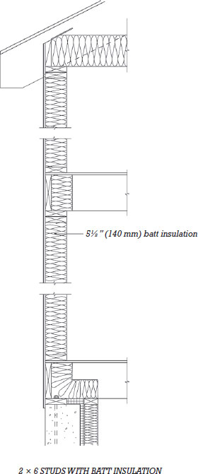
Of the two strategies illustrated in Figure 7.17, the insulation applied continuously across the wall in the right-hand example has the advantage of reducing heat loss caused by thermal bridging. Thermal bridging occurs wherever framing members interrupt the insulation, creating areas of wall with lower thermal resistance and reducing the insulating efficiency of the wall as a whole. Thus, even though the nominal R-value of the right-hand example in the figure is less than that of the one on the left, when the effects of thermal bridging are taken into account, the two are comparable in real-life energy performance. For residential buildings in colder climates, as well as for most commercial buildings, continuous insulation such as this is always required.
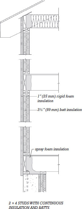
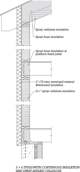
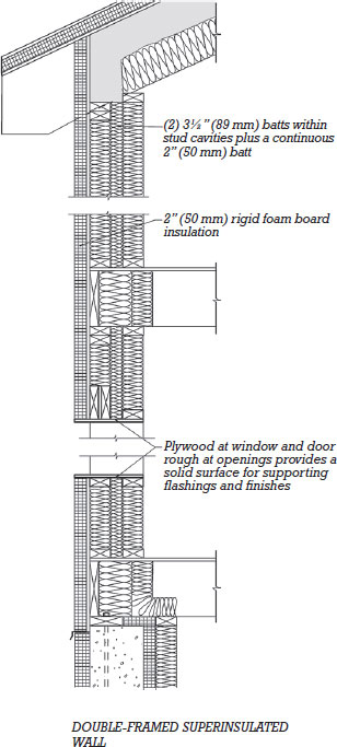
Walls may be insulated to levels greater than those illustrated in Figure 7.17 either to meet code requirements in colder climate zones, or, where desired, in excess of code requirements as a way to create an even more energy-efficient building. For example, the thermal enclosure of a building designed to the Passive House (or PassivHaus) standard must be sufficiently efficient such that no major heating or cooling systems are required to maintain the building at comfortable temperatures. (The majority of the heat required to keep a Passive House building warm comes from the body heat of its occupants, waste heat from electrical equipment, and solar gains.) Figure 7.18 illustrates two possible ways to achieve high insulation values in a wood light frame wall. The superinsulated (very high insulation value) wall on the right has an insulation value in the range of what may be required in a Passive House project in a cold climate.
Figure 7.18 Two examples of wall assemblies that achieve insulation values exceeding current code requirements for any North American climate zone. Left, a 2 × 6 (38 × 140 mm) framed wall is insulated with spray-applied cellulose and a continuous, 3-in. (76-mm) layer of semi-rigid mineral wool insulation on the outside of the sheathing. This assembly achieves an insulation value of approximately R-32 (RSI-5.6). Right, a double-framed, superinsulated wall with a total of 9 in. (229 mm) of glass fiber batts and a continuous, 2-in. (51-mm) layer of rigid foam insulation. This wall attains a value of approximately R-42 (RSI-7.4). As an alternative, a wall such as this can be built with the inner frame loadbearing rather than the outer frame as shown here. By stopping framing for floors and roofs at the inner bearing wall, thermal bridging at these locations can be reduced further. However, this approach may also be more difficult and costly to construct.
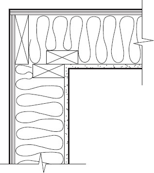
Heat loss due to thermal bridging across the wall cavity can also be reduced with modified framing techniques. Figures 7.19 and 7.20 illustrate details that reduce the area of solid framing at wall corners and headers over doors and window openings. Advanced framing techniques, discussed in Chapter 5, also significantly reduce thermal bridging in the wall frame.
Figure 7.19 Insulated headers for window and door openings that minimize thermal bridging in a 2 × 6 (38 × 140 mm) framed wall, shown in section view: (a) At the time the header is constructed, rigid foam insulation is sandwiched between the two members. Plywood nailed across the bottom of the headers allows attachment of finishes. (b) A double header is installed flush with the exterior. Later, rigid foam insulation can be added on the interior side. A nailer provides attachment for wall finishes.
(a)
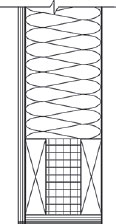
(b)
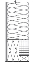
Figure 7.20 Insulated corner details that minimize thermal bridging in a 2 × 6 (38 × 140 mm) framed wall, shown in plan view: (a) Each wall frame ends with a full 2 × 6 stud. A single 2 × 4 nailer is added to accept fasteners from the interior wall finish. (b) For even greater thermal efficiency, one wall frame ends with a 2 × 4 (38 × 89 mm) stud flush with the interior surface.
(a)
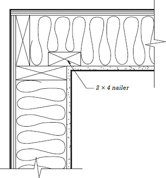
(b)
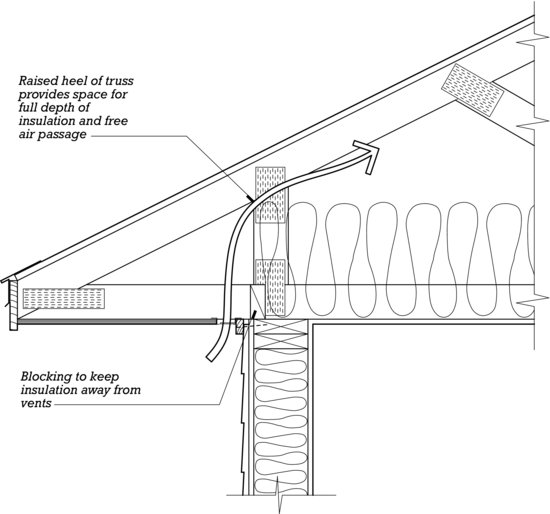
Insulation continuity can also become compromised where ceiling insulation under a sloped roof must be compressed in the diminishing space between the roof sheathing and the top of the exterior wall, as can be seen in Figure 7.17. A raised-heel roof truss is one way to overcome this problem (Figure 7.21).
Figure 7.21 A raised-heel roof truss provides plenty of space for attic insulation at the eave.
Minimum insulation values for other parts of the building enclosure, such as roofs, basement walls, and slabs on grade, are treated similarly, with lower insulation values permitted in milder climates and higher values required in climates that are more severe.
Radiant Barriers
In warmer regions, radiant barriers may be used in roofs and walls to reduce the flow of heat into the building. These are thin sheets or panels faced with a bright metal foil that blocks the transmission of infrared (heat) radiation. Radiant barriers can be installed in various locations within the wall or roof. However, the reflective surface must face an airspace in order to function. In one configuration, air barriers are located close to the exterior side of the wall or roof assembly, in a ventilated airspace. The radiant barrier reflects the very high temperatures experienced by the outermost skin of the building and the ventilated space convectively exhausts accumulated heat. Alternatively, a radiant barrier may be attached to the underside of roof framing in an attic. In this location, the barrier is equally effective at preventing the radiation of heat downward. A potential shortcoming of radiant barriers is their loss of effectiveness over time if the reflective surface becomes dulled by dust, grime, or corrosion.
Vapor Retarders
A vapor retarder (also called, less accurately, a vapor barrier) is a material placed on the warm side of thermal insulation to prevent water vapor (humidity) from diffusing into the insulation where it could condense into liquid. In the International Residential Code, vapor retarders are grouped accordingly to their relative resistance to water vapor diffusion. Class I vapor retarders are the most resistant; that is, they have the lowest vapor permeance. Class II and III retarders are each increasingly permeable.
Where vapor retarders are used, they are normally placed on the interior (warm) side of the insulation. Polyethylene plastic sheet, a Class I vapor retarder, is stapled to the face of wood framing after the insulation has been installed in the framing cavities (Figure 7.14(a)). To further improve its performance (as well as to control air leakage), the edges of the sheets are lapped and taped or sealed, and penetrations at electrical outlets, plumbing, and other such elements are carefully sealed as well. Asphalt-coated kraft paper facing available with many batt insulation products is a Type II vapor retarder (Figure 7.14(b)). The insulation is installed with the paper side facing inward and the paper tabs that extend beyond the edges of the insulation are stapled to the face of the adjacent framing members. Latex paint applied over conventional interior gypsum wallboard is an example of a Class III vapor retarder.
- Insulation increases occupant comfort and reduces the energy consumed to heat and cool buildings to a fraction of what it would otherwise be.
- The cost to insulate buildings gets paid back through energy savings many times over the life of the building.
- Insulating buildings beyond code minimums can contribute to credits in LEED and other sustainability rating systems.
- Natural fiber insulation materials typically are non-irritating and, as long as safe binders are used, do not have harmful emissions.
- Products made from wood and paper have high recycled materials content.
- Products derived from plants and animals require relatively little energy to manufacture and are often rapidly renewable. However, some of these products are transported great distances to market (for example, lamb's wool), which somewhat increases their total energy content.
- Products made from plants contribute to the sequestration of carbon that might otherwise be emitted into the Earth's atmosphere as carbon dioxide gas, a major contributor to global warming.
- Nontraditional insulation products may not be readily available locally, and may not be extracted and processed locally.
- The embodied energy of glass fiber insulation is approximately 13,000 BTU per pound (30 MJ/kg) and of mineral fiber insulation, 6300 BTU per pound (15 MJ/kg).
- The phenol-formaldehyde binder historically used in glass and mineral fiber batts can release low levels of formaldehyde gas, a recognized carcinogen. Formaldehyde-free alternatives are now readily available.
- Glass fiber insulation may contain up to 40 percent recycled material, and slag fiber insulation up to 70 percent. Rock wool insulation may include recycled slag fibers as well.
- Glass and mineral fiber insulation made with locally extracted and processed materials are available throughout many parts of North America.
- When airborne, glass and mineral fibers can irritate the skin and lungs. Installers must wear skin and breathing protection.
- Cotton fiber insulation does not emit VOCs or chemical irritants.
- Cotton fiber insulation is made from up to 80 percent recycled content and up to 70 percent rapidly renewable resource (cotton).
- No skin or breathing protection is required for installers.
- Aerogel is a silicon-based foam only recently introduced to the building industry as an insulating product. It has an embodied energy of approximately 23,000 BTU per pound (53 MJ/kg).
- Aerogel's very high insulating value makes it especially useful where limited space renders alternative insulation materials impractical.
- Skin and breathing protection are required for installers.
- The embodied energy of cellulose insulation is approximately 1000 BTU per pound (2.5 MJ/kg).
- Cellulose insulation is made from 85 percent recycled paper products, primarily newspaper.
- The binders used with cellulose insulation are simple glues that do not outgas.
- Cellulose insulation made with locally extracted and processed materials is available throughout many parts of North America.
- Installers must wear skin and breathing protection.
- Lamb's wool has an insulation value comparable to that of other fibrous insulation products. Its manufactured embodied energy is very low. Even when the energy required to ship this product from its source (New Zealand) to North America is accounted for, overall energy content is still quite low: approximately 1.6 BTU per pound (690 MJ/kg).
- Lamb's wool is a rapidly renewable material.
- Lamb's wool does not emit VOCs or chemical irritants.
- No skin or breathing protection is required for installers.
- Plastic foam materials are made in large part from petroleum, a nonrenewable resource.
- Polystyrene foam has an embodied energy of about 38,000 BTU per pound (90 MJ/kg). Polyisocyanurate and spray-applied foam insulation have an embodied energy of about 30,000 BTU per pound (70 MJ/kg).
- Plastic foams have high insulation values, absorb little if any moisture, and are air impermeable, beneficial characteristics not readily available in many other insulating materials.
- Polystyrene foam can include recycled styrene and polystyrene in its manufacture.
- Extruded polystyrene, polyisocyanurate, and polyurethane foams were formerly manufactured using HCFC, an ozone-depleting blowing agent. All are now manufactured with chemicals less harmful to the atmosphere, although some may still retain higher global warming potential than alternative products due to the release over time of these blowing agents into the atmosphere.
- Expanded polystyrene foam (bead foam) is made using pentane gas as a blowing agent. This chemical does not contribute to global warming.
- Skin and breathing protection are required when installing spray foams.
The importance of the vapor retarder in an insulated assembly increases with colder climates. But climate is not the only consideration. For example, the International Residential Code requires Type I or II vapor retarders for buildings in roughly the upper half to two-thirds of the continental United States. However, where exterior walls are designed to be more tolerant of high rates of vapor diffusion without harmful condensation, more permeable Type III vapor retarders may be used. (Such walls may be constructed with ventilated exterior cladding, insulated sheathing, or relatively permeable exterior sheathing products.) In the National Building Code of Canada, the insulated enclosure of small buildings must have vapor retarders comparable in performance to Class I or II.
In mixed or hot climates, the addition of vapor retarders where none is required or use of a vapor retarder with a much lower vapor permeance than needed should be approached with caution. This can lead to the inadvertent entrapment of water within the wall. For more information about vapor retarders in buildings, see Chapter 16.
Air Barriers
Air barriers control the leakage of air through the building enclosure. They significantly reduce building energy consumption and help protect enclosure assemblies from moisture condensation by restricting the infiltration of humid air.
Air barriers appear in some form in all insulated enclosures. Housewraps applied over exterior sheathing are one common way to incorporate an air barrier into wood light frame buildings. Or, when plastic sheeting used as a vapor retarder is carefully sealed against air leakage, it can function effectively as an air barrier. As an alternative to traditional building papers or housewraps, liquid air/weather barrier membranes can be applied to wall and roof sheathing; these provide the necessary moisture resistance and act as highly effective air barriers when combined with special tapes and sealants to seal around openings and penetrations in the wall.
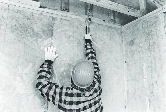
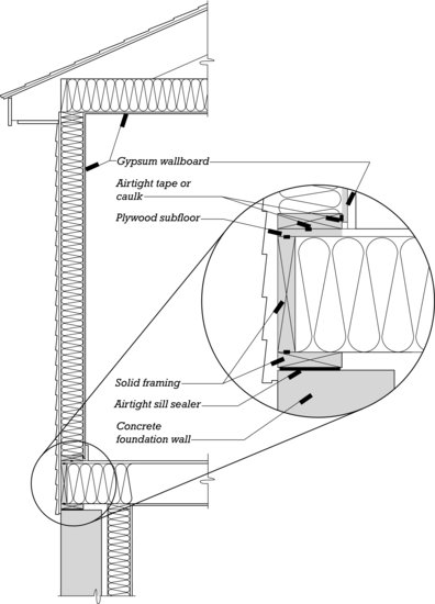
The airtight drywall approach (ADA) relies on the gypsum wallboard (drywall) panels used to finish interior walls and ceilings to create an effective air barrier (Figure 7.22). Careful attention must be given to details of construction with this method: Potential air leakage paths around the edges of gypsum panels and between abutting framing members must be sealed with compressible foam tape gaskets or joint sealants during the installation of these members; gypsum board is applied to all the interior surfaces of the outside walls before the interior partitions are framed, eliminating potential air leaks where these partitions intersect; and gaskets, sealants, or special airtight boxes are used to seal air leakage paths around electrical fixtures and other penetrations.
Figure 7.22 An air barrier system must form a continuous airtight boundary between the inside and outside of the building. In the ADA, the air barrier system is constructed of gypsum wallboard, wood framing members, and the concrete foundation wall (the shaded elements in the figure). Tapes and caulks (see the enlarged inset) are used to seal leakage paths between these components.
The ADA requires careful attention to joint sealing throughout rough framing and drywalling operations. A related system, simple caulk and seal, relies on the strategic application of joint sealants after framing and drywalling are complete to achieve much the same result as the ADA. Simple caulk and seal is easier to coordinate, because the joint sealing occurs separately from the work of other trades. However, it may be less successful at eliminating air leakage paths that become concealed and inaccessible before the sealing work takes place.
Many energy codes require blower door testing once the insulation and air barrier components of the building enclosure are fully in place. In this test, a large fan is temporarily installed into an exterior door opening and used to pressurize the entire building interior to a specified level. Calculations are then performed to determine the rate of air leakage through the complete building enclosure. If the leakage rate exceeds that permitted by code, the sources of leakage are sought out and additional testing is performed to bring the building into compliance. The permitted rate of air leakage varies, with buildings in colder regions requiring more airtight enclosures than those in milder ones. The role of the air barrier in the building enclosure is discussed in more detail in Chapter 19.
Infiltration and Ventilation
Reducing the flow of heat and air through the building enclosure reduces energy consumption. However, tightly constructed homes or apartment buildings may exchange so little air with the outdoors that if they are not adequately ventilated, indoor moisture, odors, and chemical pollutants can build up to intolerable or unhealthful levels. Opening a window to ventilate the dwelling is one way to introduce fresh air, but during heating or cooling seasons this wastes fuel. A better solution is a mechanical ventilation system designed to supply fresh air to interior spaces at a controlled and consistent rate. Such a ventilation system may be integrated with a forced-air heating or cooling system, or it may be dedicated solely to satisfying ventilation needs. For greater energy efficiency, a heat recovery ventilator or energy recovery ventilator—devices that recover heat from the air exhausted from the building and add it to the outside air that is drawn in—may be parts of such a system. Nonresidential buildings of wood light frame construction generally require higher rates of ventilation than residential structures, and here, too, low-infiltration construction and appropriately designed ventilation systems are important to maintaining a healthful and comfortable interior environment while also reducing heating and cooling costs.
WALL AND CEILING FINISH
Gypsum-based plaster and drywall finishes have always been the most popular for walls and ceilings in wood frame buildings. Their advantages include substantially lower installed costs than any other types of finishes, adaptability to either painting or wallpapering, and, importantly, a degree of fire resistance that offers considerable protection to a combustible frame. Three-coat gypsum plaster applied to wood strip lath was the prevalent wall and ceiling finish system until the Second World War, when gypsum board (also called drywall) came into increasing use because of its lower material cost, more rapid installation, and utilization of less skilled labor. More recently, veneer plaster systems have been developed that offer surfaces of a quality and durability superior to those of gypsum board, often at comparable prices.
Plaster, veneer plaster, and gypsum board finishes are covered in detail in Chapter 23. Gypsum board remains the favored material for small builders who do all the interior finish work in a building themselves, because the skills and tools it requires are largely those of carpenters rather than plasterers. In geographic areas where there are plenty of skilled plasterers, veneer plaster captures a substantial share of the market. Almost everywhere in North America, there are subcontractors who specialize in gypsum board installation and finishing and who are able to finish the interior surfaces of larger projects, such as apartment buildings, retail stores, and rental office buildings, as well as individual houses, at highly competitive prices.
In most small buildings, all wall and ceiling surfaces are covered with plaster or gypsum board. Even wood paneling should be applied over a gypsum board backup layer, for increased fire resistance. In buildings that require fire walls between dwelling units or fire separation walls between areas with different uses, a gypsum board wall of the required degree of fire resistance can be installed, eliminating the need to employ masons to put up a wall of brick or concrete masonry (Figures 5.67 and 5.68).
MILLWORK AND FINISH CARPENTRY
Millwork (so named because it is manufactured in a planing and molding mill) includes all the wood interior finish components of a building. Millwork is generally produced from much higher-quality wood than that used for framing: The softwoods used are those with fine, uniform grain structure and few defects, such as sugar pine, Ponderosa pine, or poplar. Flooring, stair treads, and millwork intended for transparent finish coatings such as varnish or shellac are customarily made of hardwoods such as red and white oak, cherry, mahogany, or walnut, or of similar quality hardwood plywoods.
Moldings are also produced from high-density plastic foams, parallel strand lumber, and medium-density fiberboard as a way of reducing costs and minimizing moisture expansion and contraction. All these materials must be painted.
The quality of millwork is regulated by the Architectural Woodwork Institute (AWI), which defines three grades: Economy, Custom, and Premium. Economy Grade cabinetry and millwork represents the minimum expectation of quality. Custom Grade provides a well-defined degree of control over the quality of materials, workmanship, and installation and is the most commonly specified grade. Premium is the most expensive grade, and is reserved for the very finest cabinets and millwork.
Millwork is manufactured and delivered to the building site at a very low moisture content, typically about 10 percent, so it is important to protect it from moisture and high humidity before and during installation to avoid swelling and distortions. The humidity within the building is frequently high at the conclusion of plastering or gypsum board work. The framing lumber, concrete work, masonry mortar, plaster, drywall joint compound, and paint are still diffusing large amounts of excess moisture into the interior air. As much of this moisture as possible should be ventilated to the outdoors before finish carpentry (the installation of millwork) commences. Windows should be left open for a few days, and in cool or damp weather the building's heating system should be turned on to raise the interior air temperature and help drive off excess water. In hot, humid weather, the air conditioning system should be activated to dry the air.
Figure A A cutaway view of a conventional masonry fireplace. Concrete masonry is used wherever it will not show, to reduce labor and material costs, but if hollow concrete blocks are used, they must be filled solid with grout. The damper and ash doors are prefabricated units of cast iron, as is a combustion air inlet in the hearth (not shown here) that connects with a sheet metal duct to an outdoor air intake. The flue liners are made of fired clay and are highly resistant to heat. The flue from the furnace or boiler in the basement slopes as it passes the firebox so as to adjoin the fireplace flue and keep the chimney as small as possible.
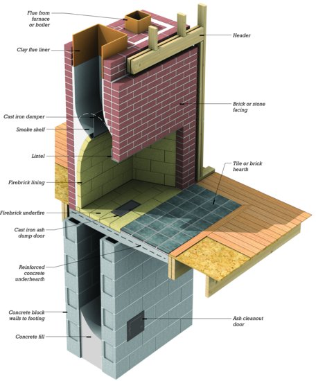
Figure B The critical dimensions of a conventional masonry fireplace, keyed to the table in Figure C. Dimension D, the depth of the hearth, is commonly required to be 16 inches (405 mm) for fireplaces with openings up to 6 square feet (0.56 m2) and 20 inches (510 mm) if the opening is larger. The side extension of the hearth, E, is usually fixed at 8 inches (200 mm) for smaller fireplace openings and 12 inches (305 mm) for larger ones.
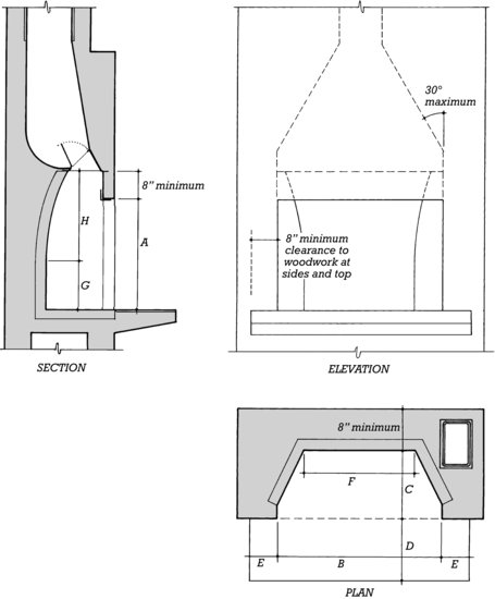
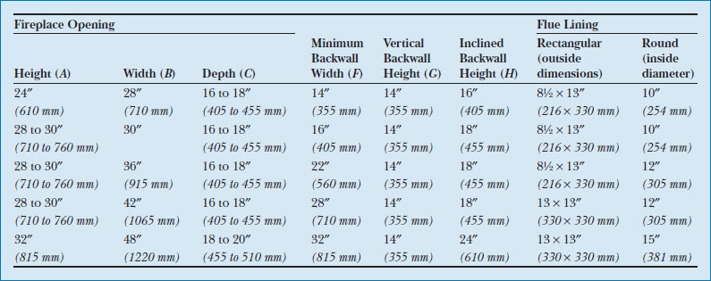
Figure C Recommended proportions for conventional masonry fireplaces, based largely on figures given in Ramsey and Sleeper, Architectural Graphic Standards (9th ed.), Hoboken, NJ, John Wiley & Sons, Inc., 1994.
Interior Doors
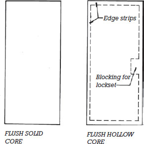
Figure 7.23 illustrates five doors that fall into three general categories: Z-brace, panel, and flush. Z-brace doors, mostly built on site, are used infrequently because they are subject to distortions and large amounts of moisture expansion and contraction in the broad surface of boards whose grain runs perpendicular to the width of the door. Panel doors were developed centuries ago to minimize dimensional changes and distortions caused by the seasonal changes in the moisture content of the wood. They are widely available in ready-made form from millwork dealers. Flush doors are smooth slabs with no surface features except the grain of the wood. They may be either solid core or hollow core. Solid-core doors consist of two veneered faces glued to a solid core of wood blocks or bonded wood chips (Figure 7.24). They are much heavier, stronger, and more resistant to the passage of sound than hollow-core doors and are also more expensive. In residential buildings, their use is usually confined to entrance doors, and because of their natural resistance to fire, doors between car garages and a residence. However, they are frequently installed throughout commercial and institutional buildings, where doors are subject to heavier use. Hollow-core doors have two thin plywood faces separated by an airspace. The airspace is maintained by an interior grid of wood or paperboard spacers to which the veneers are bonded. Flush doors of either type are available in a variety of veneer species, the least expensive of which are intended to be painted.
Figure 7.23 Types of wood doors.
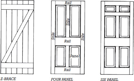
Figure 7.23 (Continued)
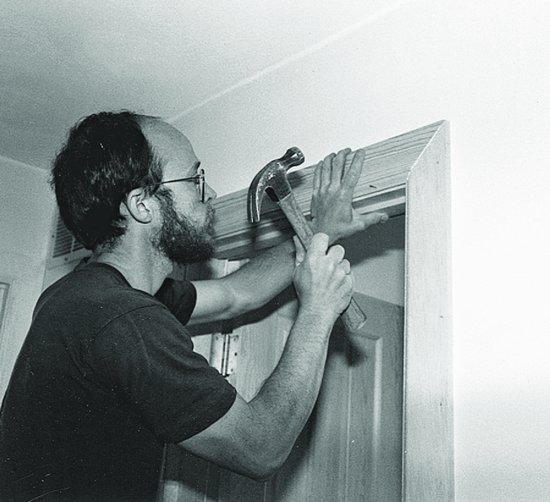
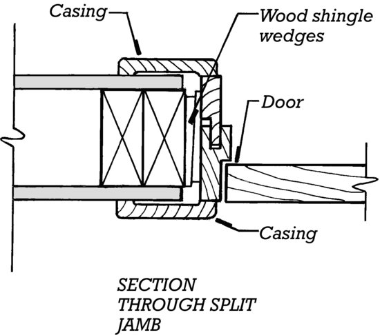
For speed and economy of installation, most interior doors are furnished prehung, meaning that they have been hinged and fitted to frames at the mill. The carpenter on the site merely tilts the prehung door and frame unit up into the rough opening, plumbs it carefully with a spirit level, shims it with pairs of wood shingle wedges between the finish and rough jambs, and nails it to the studs with finish nails through the jambs (Figure 7.25). Casings are then nailed around the frame on both sides of the partition to close the ragged gap between the door frame and the wall finish (Figure 7.26). To save the labor of applying casings, door units can also be purchased with split jambs that enable the door to be cased at the mill. At the time of installation, each door unit is separated into halves, and the halves are installed from opposite sides of the partition to telescope snugly together before being nailed in place (Figure 7.27).
Figure 7.24 Edge details of three types of wood doors. The panel is loosely fitted to the stiles and rails in a panel door to allow for moisture expansion of the wood. The spacers and edge strips in hollow-core doors have ventilation holes to equalize air pressures inside and outside the door.
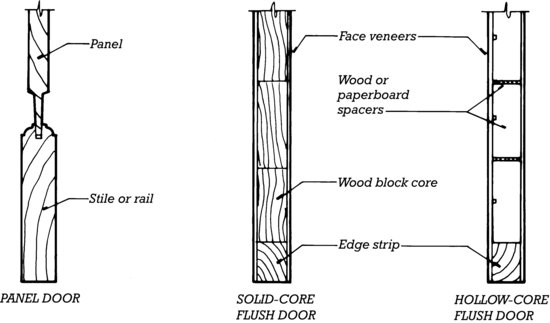
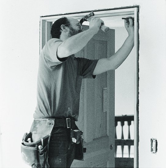
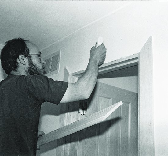
Figure 7.25 Installing a door frame in a rough opening. The shingle wedges at each nailing point are paired in opposing directions to create a flat, precisely adjustable shim to support the frame.
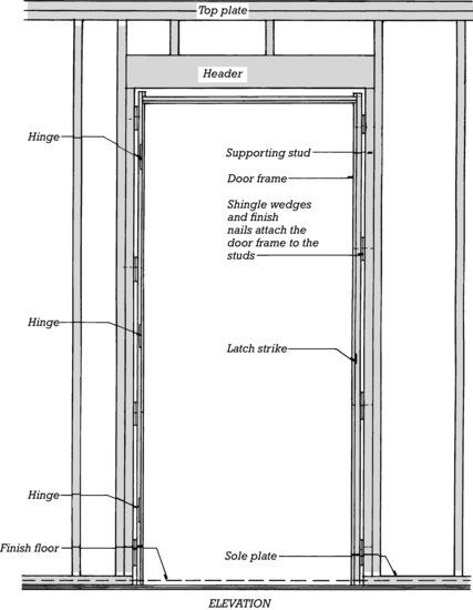
Figure 7.26 Casing a door frame. (a) The heads of the finish nails in the frame are recessed below the surface of the wood with a steel nail set. (b) The top piece of casing, mitered to join the vertical casings, is ready to install, and glue is spread on the edge of the frame. (c) The top casing is nailed into place. (d) The nails are set below the surface of the wood, ready for filling. (Photos by Joseph Iano.)
(a)
(b)
(c)
(d)
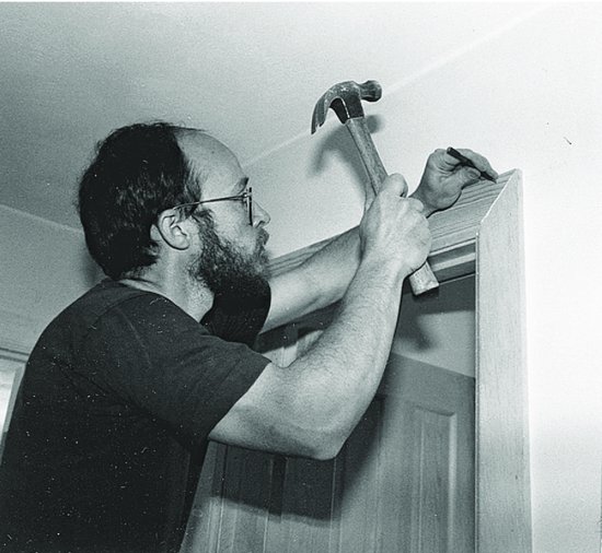
Figure 7.27 A split-jamb interior door arrives on the construction site prehung and precased. The halves of the frame are separated and installed from opposite sides of the partition.
Window Casings and Baseboards
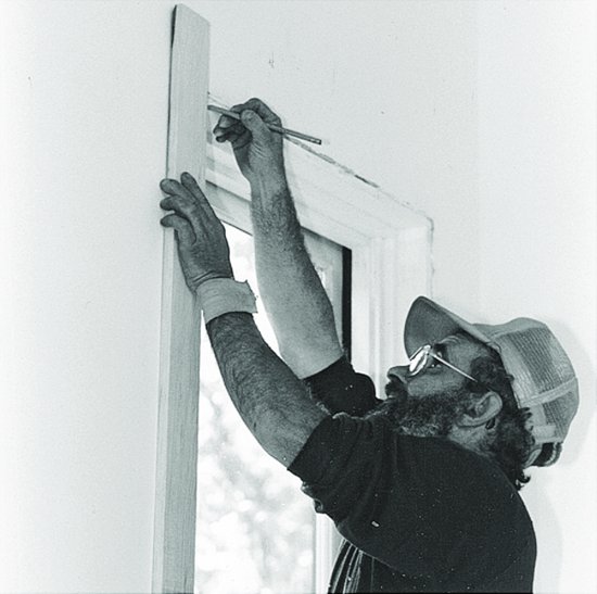
Windows are cased in much the same manner as doors (Figures 7.28 and 7.29). After the finish flooring is in place, baseboards (see Figures 7.36K–N and 24.31) are installed to cover the gap between the flooring and the wall finish and to protect the wall finish against damage by feet, furniture legs, and cleaning equipment.
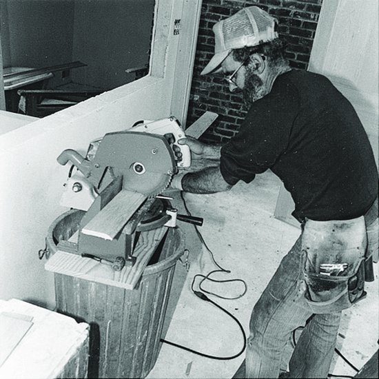
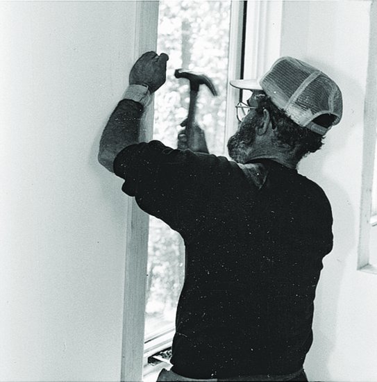
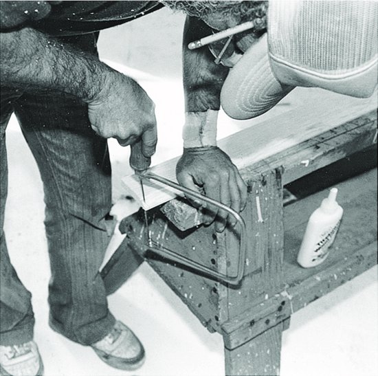
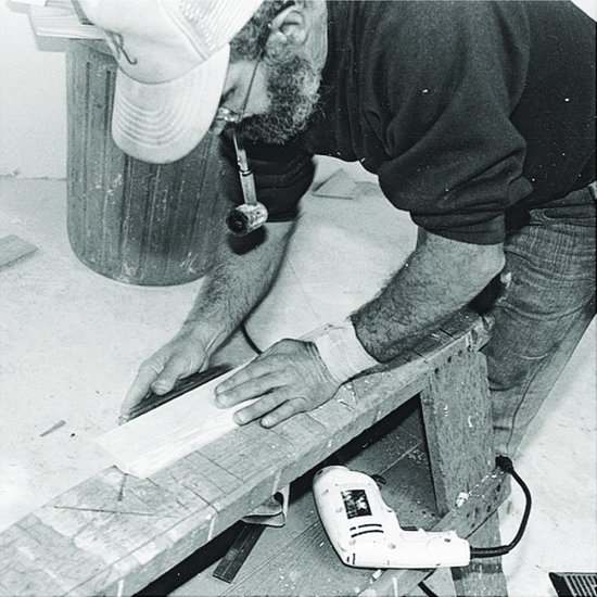
Figure 7.28 Casing a window. (a) Marking the length of a casing. (b) Cutting the casing to length with a power miter saw. (c) Nailing the casing. (d ) Coping the end of a molded edge of an apron with a coping saw so that the molding profile will terminate neatly at the end of the apron. (e) Planing the edge of the apron, which has been ripped (sawn lengthwise, parallel to the grain of the wood) from wider casing stock. (f ) Applying glue to the apron. (g) Nailing the apron, which has been wedged temporarily in position with a stick. (h) The coped end of the apron, in place. (i) The cased window, ready for filling, sanding, and painting. (Photos by Joseph Iano.)
(a)
(b)
(c)
(d)
(e)
(f)
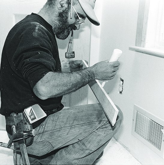
(g)
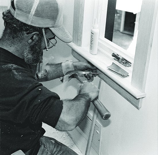
(h)
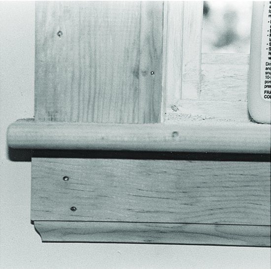
(i)
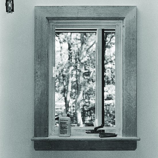
Figure 7.29 Simple but carefully detailed and skillfully crafted window casings in a restaurant. (Woo & Williams, Architects. Photographer: Richard Bonarrigo.)
When installing casings or baseboards, the carpenter recesses the heads of finish nails below the surface of the wood, traditionally using a hammer and a nail set (a hardened steel punch), or, as is more likely today, a powered finish nail gun. Later, the painters will fill these nail holes with a paste filler and sand the surface smooth after the filler has dried so that the holes will be invisible in the painted woodwork. For transparent wood finishes, nail holes are usually filled after the finishes have been applied, using wax-based fillers that are supplied in a range of colors to match the full range of wood species.
The nails in casings and baseboards must reach through the plaster or gypsum board to penetrate the framing members beneath in order to make a secure attachment. Eight- or ten-penny finish or casing nails are customarily used.
Cabinets
Cabinets for kitchens, bathrooms, bedrooms, workrooms, and other spaces may be either custom- or factory-fabricated. Custom wood cabinets are fabricated in specialty woodworking shops according to drawings and specifications prepared individually for each project. Like quality millwork, custom cabinets are constructed to AWI specifications, usually Premium or Custom Grade. Less expensive, manufactured wood cabinets are factory-manufactured to standard sizes and configurations. Both types of cabinets are usually delivered to the construction site fully finished.
On the construction site, cabinets are installed by shimming against wall and floor surfaces as necessary to make them level and screwing through the backs of the cabinet units into the wall studs (Figures 7.30 and 7.31). The tops are then attached with screws driven up from the cabinets beneath. Kitchen and bath countertops are cut out for built-in sinks and lavatories, which are subsequently installed by the plumber.
Figure 7.30 Prepainted wood kitchen cabinets installed before the installation of shelves, drawers, doors, and countertops. (Photo by Edward Allen.)
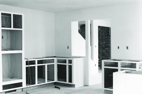
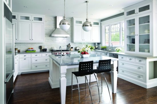
Figure 7.31 Custom, paneled wood cabinetry contrasts elegantly with contemporary kitchen fixtures and furnishings. The wall behind the cabinets is finished with stone tile, and the floor with solid wood strip flooring. (Design by Jane Lockhart; courtesy NKBA.)
Finish Stairs
Finish stairs are either constructed in place (Figures 7.32 and 7.33) or shop built (Figures 7.34 and 7.35). Shop-built stairs tend to be less expensive to build and easier to install. Constructing stairs on site requires highly skilled carpenters but allows stairs to be built to any configuration and fitted more closely to framing or finish irregularities. Stair treads are usually made of wear-resistant hardwoods such as oak or maple. Risers and stringers may be made of any reasonably hard wood, such as oak, maple, or Douglas fir.
Figure 7.32 Top : Stair terminology and clearances for wood frame residential construction. Bottom : Types of stairs. 1. Straight run. 2. L-shaped stair with landing. 3. 180-degree turn with landing. 4. L-shaped stair with winders (triangular treads). Winders are helpful in compressing a stair into a small space, but are perilously steep where they converge, and their treads become much too shallow for comfort and safety. Building codes limit their minimum dimensions and restrict their use to within dwelling units. 5. L-shaped stair whose winders have an offset center. The offset center can increase the minimum tread dimension to within legal limits. 6. A spiral stair (in reality a helix, not a spiral) consists entirely of winders and is generally illegal for any use but a secondary stair in a single-family residence. 7. A spiral or circular stair with an open center of sufficient diameter can have its treads dimensioned to legal standards.
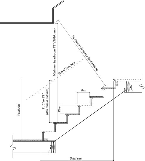
Figure 7.32 (Continued)
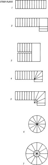
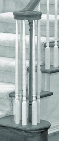
Figure 7.33 Constructing a finished stair in place. The joint between the riser and the open stringer is a miter. The balusters, posts, and handrail are purchased ready-made from millwork suppliers and cut to fit.

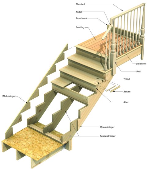
Figure 7.34 A shop-built stair. All the components are glued firmly together in the shop, and the stair is installed as a single piece.
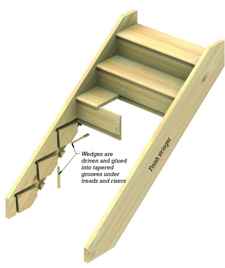
Figure 7.35 (a) A worker completes a highly customized curving stair in a shop. (b) Balusters, newel post, and handrail are finely finished in a historical style. (Courtesy of Staircase & Millwork Co., Alpharetta, GA.)
(a)
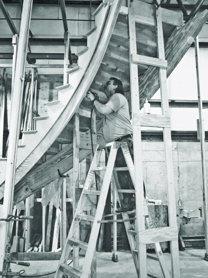
(b)
Three openings are required in stair-cases; the first is the door thro' which one goes up to the staircase, which the less it is hid to them that enter into the house, so much the more it is to be commended. And it would please me much, if it was in a place, where before that one comes to it, the most beautiful part of the house was seen; because it makes the house (even tho' small) seem very large; but however, let it be manifest, and easily found. The second opening is the windows that are necessary to give light to the steps; they ought to be in the middle, and high, that the light may be spread equally every where alike. The third is the opening thro' which one enters into the floor above; this ought to lead us into ample, beautiful, and adorned places.
—Andrea Palladio, The Four Books of Architecture, 1570
Miscellaneous Finish Carpentry
Finish carpenters install dozens of miscellaneous items in the average building: closet shelves and poles, pantry shelving, bookshelves, wood paneling, chair rails, picture rails, ceiling moldings, mantelpieces, laundry chutes, folding attic stairs, access hatches, door hardware, weatherstripping, doorstops, and bath accessories (towel bars, paper holders, and so on). Many of these items are available ready-made from millwork and hardware suppliers (Figures 7.36 and 7.37), but others have to be crafted by the carpenter.
Figure 7.36 Some common molding patterns for wood interior trim. A and I are crowns, C is a bed, and D and E are coves. All are used to trim the junction of a ceiling and a wall. F is a quarter-round for general-purpose trimming of inside corners. Moldings G–J are used on walls. G is a picture molding, applied near the top of a wall so that framed pictures can be hung from it at any point on special metal hooks that fit over the rounded portion of the molding. H is a chair rail, installed around dining rooms to protect the walls from damage by the backs of chairs. I is a panel molding and J is a batten, both used in traditional paneled wainscoting. Baseboards (K–N) include three single-piece designs and one traditional design (K ) using a separate cap molding and shoe in addition to a piece of S4S stock that is the baseboard itself (see also Figure 24.31). Notice the shallow groove, also called a “relieved back,” in the single-piece baseboards and many other flat moldings on this page. This serves to reduce cupping forces on the piece and makes it easier to install even if it is slightly cupped. Designs AA–FF are standard casings for doors and windows. GG, HH, and II are handrail stock. MM is representative of a number of sizes of S4S material available to the finish carpenter for miscellaneous uses. NN is lattice stock, also used occasionally for flat trim. OO is square stock, used primarily for balusters. PP represents several available sizes of round stock for balusters, handrails, and closet poles. Wood moldings are furnished in either of two grades: N Grade, for transparent finishes, must be of a single piece. P Grade, for painting, may be finger-jointed or edge-glued from smaller pieces of wood. P Grade is less expensive because it can be made up of short sections of lower-grade lumber with the defects cut out. Once painted, it is indistinguishable from N Grade. The shapes shown here represent a fraction of the moldings that are generally available from stock. Custom molding patterns can be produced easily because the molding cutters used to produce them can be ground quickly to the desired profiles, working from the architect's drawings.
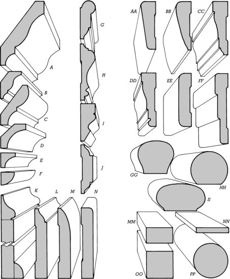
Figure 7.37 Fireplace mantels are available from specialized mills in a number of traditional and contemporary designs. Each mantel is furnished largely assembled, but is detailed in such a way that it can easily be adjusted to fit any fireplace within a wide range of sizes. (Courtesy of Mantels of Yesteryear, P.O. Box 908, 70 West Tennessee Ave., McCaysville, GA 30555; www.mantelsofyesteryear.com; (706) 492-5534, (706) 492-3758 fax.)
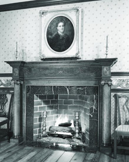
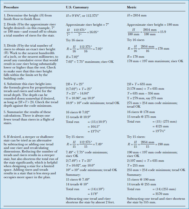
Figure A Dimensional limitations for stairs as established by the IBC.
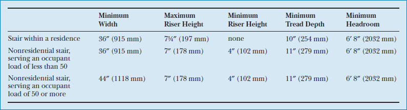
Figure B A sample calculation for proportioning a residential stair. You can download a PDF of this Figure at http://www.wiley.com/go/aflblce6ne.
FLOORING AND CERAMIC TILE WORK
Before finish flooring can be installed, the subfloor is scraped free of plaster droppings and swept thoroughly. Underlayment panels of C–C Plugged plywood or particleboard (in areas destined for resilient flooring materials or carpeting) are glued and nailed over the subfloor, their joints staggered with those in the subfloor to eliminate weak spots. The thicknesses of the underlayment panels are chosen to make the finished floor surfaces as nearly equal in level as possible at junctions between different flooring materials.
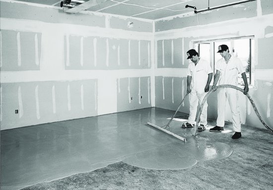
In multistory wood light frame commercial and apartment buildings, specially formulated lightweight poured gypsum or portland cement underlayment is often placed over the subfloor. This has a threefold function: It provides a smooth, level surface for finish floor materials; it furnishes additional fire resistance to the floor construction; and it reduces the transmission of sound through the floor to the apartment or office below. The gypsum or concrete is formulated with superplasticizer additives that make it self-leveling as it is applied (Figure 7.38). A minimum thickness is ¾ inch (19 mm). Poured underlayments are also used to level floors in older buildings, to add fire and sound resistance to precast concrete floors, and to embed plastic tubing or electric resistance wires for in-floor radiant heat.
Figure 7.38 Workers apply a gypsum underlayment to an office floor. The gypsum is pumped through a hose and distributed with a straightedge tool. Because the gypsum seals against the bottoms of the interior partitions, it can also help reduce sound transmission from one room to another. (Copyright Gyp-Crete Corporation, Hamel, MN.)
Floor finishing operations require cleanliness and freedom from traffic, so members of other trades are banished from the area as the flooring materials are applied. Hardwood flooring is sanded level and smooth after installation, then vacuumed to remove the sanding dust. The finish coatings are applied in as dust-free an atmosphere as possible to avoid embedded specks. Resilient-flooring installers vacuum the underlayment meticulously so that particles of dirt will not become trapped beneath the thin flooring and cause small bumps in the surface. The finished floors are often covered with heavy sheet or thin board material to protect them during the final few days of construction activity. Carpet installation is less sensitive to dust, and the installed carpets are less prone to damage than hardwood and resilient floorings, but temporary coverings are applied as necessary to protect the carpet from paint spills and water stains.
The application of ceramic tile to a portland cement plaster base coat over metal lath for a shower stall is illustrated in Figure 7.39, and finished ceramic tile work is shown in Figure 7.40. Cementitious backer board may be used as a less costly substitute for a cement plaster base coat (Figure 24.28). Wood flooring installation is depicted in Figures 24.31 and 24.32. A finished hardwood floor is shown in Figures 7.41 and 24.33. The installation of ceramic tile and finish flooring materials is covered in more detail in Chapters 23 and 24.
Figure 7.39 Installing sheets of ceramic tile in a shower stall. The base coat of portland cement plaster over metal lath has already been installed. Now the tilesetter applies a thin coat of tile adhesive to the base coat with a trowel and presses a sheet of tiles into it, taking care to align the tiles individually around the edges. A day or two later, after the adhesive has hardened sufficiently, the joints will be grouted to complete the installation. (Photographs by Joseph Iano.)
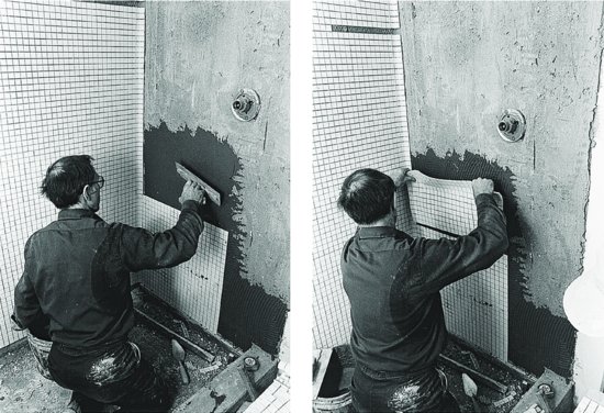
Figure 7.40 Ceramic tile is used for the floor, countertops, and backsplash in this kitchen. The border was made by selectively substituting tiles of four different colors for the white tiles used for the field of the floor. (Designer: Kevin Cordes. Courtesy of American Olean Tile.)
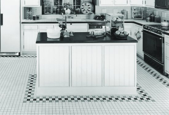
Figure 7.41 Varnished oak flooring, millwork, and casework. (Woo & Williams, Architects. Photographer: Richard Bonarrigo.)
FINISHING TOUCHES
When flooring and painting are finished, the plumbers install and activate the lavatories, water closets, tubs, sinks, and shower fixtures. Gas lines are connected to appliances and the main gas valve is opened. The electricians connect the wiring for the heating and air conditioning equipment and (if electric) water heater; mount the receptacles, switches, and lighting fixtures; and put metal or plastic cover plates on the switches and receptacles. The electrical circuits are energized and checked to be sure that they work. The smoke, heat, and carbon monoxide alarms required by most codes in residential structures, are also connected and tested by the electricians, along with any communications, entertainment, and security system wiring. The heating and air conditioning system is completed with the installation of air grills and registers, or with the mounting of metal convector covers, then turned on and tested. Painted surfaces that have been scuffed or marred are touched up, and last-minute problems are identified and corrected through cooperative effort by the contractors, the owner of the building, and the architect. The building inspector is called in for a final inspection and issuance of an occupancy permit. After a thorough cleaning, the building is ready for use.
KEY TERMS
REVIEW QUESTIONS
1. List the sequence of operations required to complete the interior of a wood light frame building and explain the logic of the order in which these operations occur.
2. What are some alternative ways of insulating the walls of a wood light frame building to R-values beyond the range normally possible with ordinary 2 × 4 (38 × 89 mm) studs?
3. Why are plaster and gypsum board so popular as interior wall finishes in wood frame buildings? List as many reasons as possible.
4. What is the level of humidity in a building at the time installation of the interior wall finishes is completed? Why? What should be done about this and why?
5. Summarize the most important things to keep in mind when designing a stair.
6. Describe the function of thermal insulation. When and where is it used?
7. Describe the function of a vapor barrier. When and where is it used?
8. Describe the purpose of an air barrier. When and where is it used?
EXERCISES
1. Design and detail a fireplace for a building that you are designing, using the information provided in this chapter to work out the exact dimensions and the information in Chapter 8 to help in detailing the masonry.
2. Design and detail a stairway for a building that you are designing. Provide complete dimensions.
3. Visit a wood frame building that you admire. Make a list of the interior finish materials and components, including finishes and species of wood where possible. How does each material and component contribute to the overall feeling of the building? How do they relate to one another?
4. Make measured drawings of millwork details in an older building that you admire. Analyze each detail to discover its logic. What woods were used and how were they sawn? How were they finished?
SELECTED REFERENCES
Architectural Woodwork Institute. AWI Quality Standards Illustrated. Reston, VA, updated regularly.
Every detail of every grade of interior woodwork and cabinetry is illustrated and described in this thick volume.
Dietz, Albert G. H. Dwelling House Construction (5th ed.). Cambridge, MA, MIT Press, 1990.
This classic text has extensive chapters with clear illustrations concerning chimneys and fireplaces, insulation, wallboard, lath and plaster, and interior finish carpentry.
Lstiburek, Joseph. Builder's Guide to Cold Climates. Westford, MA, Building Science Corporation, 2006.
This guide, along with companion guides for other major climate zones, explains the roles of insulation, vapor retarders, and air barriers in the performance of the building enclosure, and provides guidelines for the construction of energy-efficient and weather-resistant homes.
Thallon, Rob. Graphic Guide to Interior Details: For Builders and Designers. Newtown, CT, Taunton Press, 2004.
Profusely illustrated, clearly written, and encyclopedic in scope, this book offers complete guidance on interior finishing of wood light frame buildings.
WEB SITES
Interior Finishes for Wood Light Frame Construction
Author's supplementary web site: www.ianosbackfill.com/07_interior_finishes_for_wood_light_frame_construction
Thermal Insulation and Vapor Retarder
Building Science Corporation: www.buildingscience.com
Dow Chemical rigid and spray foam insulation: www.dow.com
Gypsum Association: www.gypsum.org
Icynene Corporation spray -foam insulation: www.icynene.com
Owens Corning insulation products: www.owenscorning.com
Passive House Institute (International): www.passiv.de/en/
Passive House Institute: www.passivehouse.us, www.passivehouse.ca, www.passivhaus.org.uk/, www.passiv.de/en/
Wall and Ceiling Finish
USG gypsum products: www.usg.com
Millwork and Finish
Architectural Woodwork Institute: www.awinet.org
Hardwood Plywood & Veneer Association: www.hpva.org
Jeld-Wen Windows & Doors: www.jeld-wen.com
Window and Door Manufacturers Association: www.wdma.org
Proportioning Fireplaces
Buckley Rumford Company: www.rumford.com
Flooring and Ceramic Tile Work
American Olean Tile: www.americanolean.com
Tile Council of America: www.tileusa.com