
The Chapel of St. Ignatius, Seattle University, designed by architect Steven Holl. Holl creates a striking composition of precisely detailed tilt-up concrete wall panels and architectural sheet metal roofing. (Photo by Joseph Iano.)
13
CONCRETE CONSTRUCTION
Supplementary Cementitious Materials
Steel Bars for Concrete Reinforcement
Fabrication and Erection of Reinforcing Bars
Reinforcing a Simple Concrete Beam
Reinforcing a Continuous Concrete Beam
Reinforcing Structural Concrete Slabs
Innovations in Concrete Construction
HISTORY
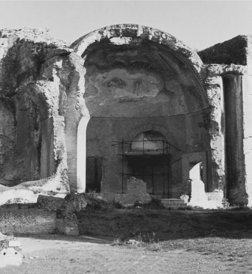
The ancient Romans, while quarrying limestone for mortar, accidentally discovered a silica- and alumina-bearing mineral on the slopes of Mount Vesuvius that, when mixed with limestone and burned, produced a cement that exhibited a unique property: When mixed with water and sand, it produced a mortar that could harden underwater as well as in the air. In fact, it was stronger when it hardened underwater. This mortar was also harder, stronger, much more adhesive, and cured much more quickly than the ordinary lime mortar to which they were accustomed. In time, it not only became the preferred mortar for use in all their building projects, but it also began to alter the character of Roman construction. Masonry of stone or brick came to be used to build only the surface layers of piers, walls, and vaults, and the hollow interiors were filled entirely with large volumes of the new type of mortar ( Figure 13.2). We now know that this mortar contained all the essential ingredients of modern portland cement and that the Romans were the inventors of concrete construction.
Figure 13.1 At the time concrete is placed, it has no form of its own. This bucket of fresh, wet concrete was filled on the ground by a transit-mix truck and hoisted to the top of the building by a crane. The worker at the right has opened the valve in the bottom of the bucket to discharge the concrete. (Reprinted with permission of the Portland Cement Association from Design and Control of Concrete Mixtures, 12th edition; PHOTOS: Portland Cement Association, Skokie, IL.)
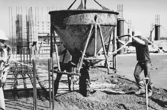
Figure 13.2 Hadrian's Villa, a large palace built near Rome between AD 125 and 135, used unreinforced concrete extensively for structures such as this dome. (Photo by Edward Allen.)
Knowledge of concrete construction was lost with the fall of the Roman Empire, not to be regained until the latter part of the 18th century, when a number of English inventors began experimenting with both natural and artificially produced cements. Joseph Aspdin, in 1824, patented an artificial cement that he named portland cement, after English Portland limestone, whose durability as a building stone was legendary. His cement was soon in great demand, and the name “portland,” for the cementitious component of concrete, remains in use today.
Reinforced concrete, in which steel bars are embedded to resist tensile forces, was developed in the 1850s by several people simultaneously. Among them were the Frenchman J. L. Lambot, who built several reinforced concrete boats in Paris in 1854, and an American, Thaddeus Hyatt, who made and tested a number of reinforced concrete beams. But the combination of steel and concrete did not come into widespread use until a French gardener, Joseph Monier, obtained a patent for reinforced concrete flower pots in 1867 and went on to build concrete water tanks and bridges of the new material. By the end of the 19th century, engineering design methods had been developed for structures of reinforced concrete and a number of major structures had been built. By this time, the earliest experiments in prestressing (placing the reinforcing steel under tension before the structure supports a load) had also been carried out, although it remained for Eugene Freyssinet in the 1920s to establish a scientific basis for the design of prestressed concrete structures.
CEMENT AND CONCRETE
Concrete is a rocklike material produced by mixing coarse and fine aggregates, portland cement, and water and allowing the mixture to harden. Coarse aggregate is normally gravel or crushed stone, and fine aggregate is sand. Portland cement, hereafter referred to simply as cement, is a fine gray powder. During the hardening, or curing, of concrete, the cement combines chemically with water to form strong crystals that bind the aggregates together, a process called hydration. During this process, considerable heat, called heat of hydration, is given off. In addition, especially as excess water evaporates from the concrete, the concrete shrinks slightly, a phenomenon referred to as drying shrinkage. The curing process, and the gradual increase in the strength of the concrete that occurs with it, does not end abruptly unless it is artificially interrupted. Rather, it tapers off over long periods of time, though, for practical purposes, concrete is normally considered cured and at full design strength after 28 days.
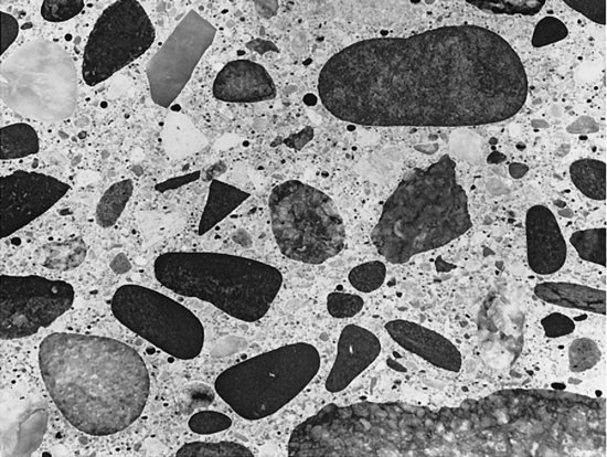
In properly formulated concrete, the majority of the volume consists of coarse and fine aggregate, proportioned and graded so that the fine particles fill the spaces between the coarse ones (Figure 13.3). Each particle is completely coated with a paste of cement and water that bonds it fully to the surrounding particles.
Figure 13.3 Photograph of a polished cross section of hardened concrete, showing the close packing of coarse and fine aggregates and the complete coating of every particle with cement paste. (Reprinted with permission of the Portland Cement Association from Design and Control of Concrete Mixtures, 12th edition; PHOTOS: Portland Cement Association, Skokie, IL.)
Cement
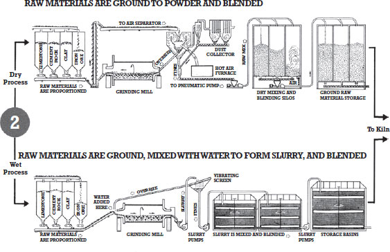
Portland cement may be manufactured from any of a number of raw materials, provided that they are combined to yield the necessary amounts of lime, iron, silica, and alumina. Lime is commonly furnished by limestone, marble, marl (a sedimentary rock), or seashells. Iron, silica, and alumina may be provided by clay or shale. The exact ingredients depend on what is readily available, and the recipe varies from one geographic region to another, often including slag or flue dust from iron furnaces, chalk, sand, ore washings, bauxite, and other minerals. To make portland cement, the selected constituents are crushed, ground, proportioned, and blended. Then they are conducted through a long, rotating kiln at temperatures of 2600 to 3000 degrees Fahrenheit (1400–1650°C) to produce clinker (Figures 13.4 and 13.5). After cooling, the clinker is pulverized to a powder finer than flour. Usually at this stage a small amount of gypsum is added to act as a retardant during the later concrete curing process. This finished powder, portland cement, is either packaged in bags or shipped in bulk. In the United States, a standard bag of cement contains 1 cubic foot (0.09 m2 ) of volume and weighs 94 pounds (43 kg).
Figure 13.4 A rotary kiln manufacturing cement clinker. The blended raw ingredients for cement are introduced into the kiln's higher end, top right in this photograph. As the kiln rotates, the ingredients slowly tumble downward toward the lower, far end. Heated air is introduced into the kiln through the large round ducts clustered around the kiln's lower end. (Photo by Joseph Iano.)
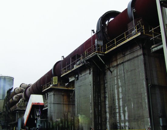
Figure 13.5 Steps in the manufacture of portland cement. (Reprinted with permission of the Portland Cement Association from Design and Control of Concrete Mixtures, 12th edition; PHOTOS: Portland Cement Association, Skokie, IL.)



The quality of portland cement is established by ASTM C150, which identifies eight different types:
| Type I | Normal |
| Type IA | Normal, air entraining |
| Type II | Moderate resistance to sulfate attack |
| Type IIA | Moderate sulfate resistance, air entraining |
| Type III | High early strength |
| Type IIIA | High early strength, air entraining |
| Type IV | Low heat of hydration |
| Type V | High resistance to sulfate attack |
Type I cement is used for most purposes in construction. Types II and V are used where the concrete will be in contact with water that has a high concentration of sulfates. Type III hardens more quickly than the other types and is employed in situations where a reduced curing period is desired (as may be the case in cold weather), in the precasting of concrete structural elements, or when the construction schedule must be accelerated. Type IV is used in massive structures such as dams, where the heat emitted during curing may raise the temperature of the concrete to damaging levels. Most cement that is manufactured in North America is designated as Type I/II, meaning it meets the requirements of both these types.
ASTM C150 also permits the addition of limestone to the finished portland cement (distinct from its use as a raw ingredient in the manufacture of clinker). This relatively recent change results in reductions in raw material consumption, energy consumption, carbon dioxide emissions, and cement dust generation during cement manufacturing.
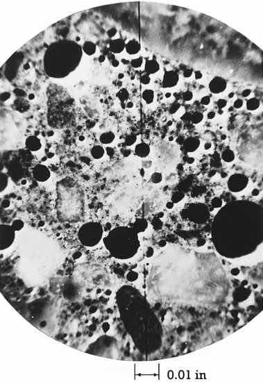
Air-entraining cements contain ingredients that cause microscopic air bubbles to form in the concrete during mixing (Figure 13.6). These bubbles, which usually comprise 2 to 8 percent of the volume of the finished concrete, improve workability during placement of the concrete and, more importantly, greatly increase the resistance of the finished concrete to damage caused by repeated cycles of freezing and thawing. Air-entrained concrete is commonly used for pavings and exposed architectural concrete in cold climates. With appropriate adjustments in the formulation of the mix, air-entrained concrete can achieve the same structural strength as normal concrete.
Figure 13.6 A photomicrograph of a small section of air-entrained concrete shows the bubbles of entrained air (0.01 inch equals 0. 25 mm). (Reprinted with permission of the Portland Cement Association from Design and Control of Concrete Mixtures, 12th edition; PHOTOS: Portland Cement Association, Skokie, IL.)
White portland cement is produced by controlling the quantities of certain minerals, such as oxides of iron and manganese, found in the ingredients of cement, that contribute to cement's usual gray color. White portland cement is used for architectural applications to produce concrete that is lighter and more uniform in color or, when combined with other coloring agents, to enhance the appearance of integrally colored concrete.
- Worldwide each year, the making of concrete consumes 1.6 billion tons (1.5 billion metric tons) of portland cement, 10 billion tons (9 billion metric tons) of sand and rock, and 1 billion tons (0.9 billion metric tons) of water, making the concrete industry the largest user of natural resources in the world.
- The quarrying of the raw materials for concrete in open pits can result in soil erosion, pollutant runoff, habitat loss, and ugly scars on the landscape.
- Concrete construction also uses large quantities of other materials—wood, wood panel products, steel, aluminum, plastics—for formwork and reinforcing.
- The total energy embodied in a pound of concrete varies, especially with the design strength. This is because higher-strength concrete relies on a greater proportion of portland cement in its mix, and the energy required to produce portland cement is very high in comparison to concrete's other ingredients. For average-strength concrete, the embodied energy ranges from about 200 to 300 BTU per pound (0.5–0.7 MJ/kg).
- There are various useful approaches to increasing the sustainability of concrete construction:
- Use waste materials from other industries, such as fly ash from power plants, slag from iron furnaces, copper slag, foundry sand, mill scale, sandblasting grit, and others, as components of cement and concrete.
- Use concrete made from locally extracted materials and local processing plants to reduce the transportation of construction materials over long distances.
- Minimize the use of materials for formwork and reinforcing.
- Reduce energy consumption, waste, and pollutant emissions from every step of the process of concrete construction, from quarrying of raw materials through the eventual demolition of a concrete building at the end of its useful life.
- In regions where the quality of the construction materials is low, improve the quality of concrete so that concrete buildings will last longer, thus reducing the demand for concrete and the need to dispose of demolition waste.
- The production of portland cement is by far the largest user of energy in the concrete construction process, accounting for about 85 percent of the total energy required. Portland cement production also accounts for roughly 5 percent of all carbon dioxide gas generated by human activities worldwide and about 1.5 percent of such emissions in North America.
- For every ton of cement clinker produced, almost a ton of carbon dioxide, a greenhouse gas, is released into the atmosphere.
- Since 1970, the North American cement industry has reduced the amount of energy expended in cement production by one-third, and the industry continues to work toward further reductions.
- The manufacture of cement produces large amounts of air pollutants and dust. In the past 35 years, the emission of particulates from cement production has been reduced by more than 90 percent.
- The cement industry is committed to reducing greenhouse gas emissions per ton of product by 10 percent from 1990 levels by the year 2020. According to the Portland Cement Association, over concrete's lifetime, it reabsorbs roughly half of the carbon dioxide released during the original cement manufacturing process.
- The amount of portland cement used as an ingredient in concrete, and as a consequence, the energy required to produce the concrete, can be substantially reduced by the addition of certain industrial waste materials with cementing properties to the concrete mix. Substituting such supplementary cementitious materials, including fly ash, silica fume, and blast furnace slag, for up to half the portland cement in the concrete, can result in as much as a one-third reduction in embodied energy of the concrete.
- When added to concrete, fly ash is most commonly substituted for portland cement at rates of between 15 and 25 p ercent. Mixes with even higher replacement rates, called high-volume-fly-ash (HVFA) concrete, are also finding increased acceptance. Concrete mixed with fly ash as an ingredient gains other benefits as well: It requires less water than normal concrete, its heat of hydration is lower, and it shrinks less—all characteristics that lead to a denser, more durable product. Research is underway to develop concrete mixes in which fly ash completely replaces all portland cement.
- Waste materials from other industries can also be used as cementing agents; wood ash and rice-husk ash are two examples. Used motor oil and used rubber vehicle tires can be employed as fuel in cement kilns. While consuming waste products from other industries, a cement manufacturing plant can, if efficiently operated, generate virtually no solid waste itself.
- Technologies currently under development aim to significantly reduce carbon dioxide emissions in comparison to current manufacturing methods. By injecting carbon dioxide into concrete during its manufacture, it may be possible to create a stronger and harder material, but with a 20 percent reduction in net carbon dioxide emissions. Carbon dioxide emissions from aluminosilicate cement manufacturing are as much as 80 to 90 percent less than those of ordinary portland cement. Cement made from magnesium produces a material that is actually carbon negative, absorbing significantly more carbon over its lifetime than is emitted during its manufacture.
- Sand and crushed stone come from abundant sources in many parts of the world, but high-quality aggregates are becoming scarce in some countries.
- In rare instances, aggregate in concrete has been found to be a source of radon gas. Concrete itself is not associated with indoor air quality problems.
- Waste materials such as crushed, recycled glass, used foundry sand, and crushed, recycled concrete can substitute for a portion of the conventional aggregates in concrete.
- Water of a quality suitable for concrete is scarce in many developing countries. Concretes that use less water by using superplasticizers, air entrainment, and fly ash could be helpful.
- A significant percentage of fresh concrete is not used because the truck that delivers it to the building site contains more than is needed for the job. This concrete is often dumped on the site, where it hardens and is later removed and taken to a landfill for disposal. An empty transit-mix truck must be washed out after transporting each batch, which produces a substantial volume of water that contains portland cement particles, admixtures, and aggregates. These wastes can be recovered and recycled as aggregates and mixing water, but more concrete suppliers need to implement schemes for doing this.
- Formwork components that can be reused many times have a clear advantage over single-use forms, which represent a large waste of construction material.
- Form release compounds and curing compounds should be chosen for low volatile organic compound content and biodegradability.
- Insulating concrete forms eliminate most temporary formwork and produce concrete walls with high thermal insulating values.
- In North America, reinforcing bars are made almost entirely from recycled steel scrap, primarily junked automobiles. This reduces resource depletion and energy consumption significantly.
- Considering only the materials production phase, concrete has a relatively high global warming potential in comparison to other major structural materials. However, once occupied, concrete buildings can be designed to operate more efficiently, for example by exploiting the energy saving potential of thermal mass. Comparative studies indicate that, over the complete material life cycle, the global warming potential of concrete buildings is at least as good as that of buildings constructed of wood or steel.
- When a concrete building is demolished, its reinforcing steel can be recycled.
- In many if not most cases, fragments of demolished concrete can be crushed, sorted, and used as aggregates for new concrete. At present, however, most demolished concrete is buried on the site, used to fill other sites, or dumped in a landfill.
- Pervious concrete can be used to make porous pavings that allow stormwater to filter into the ground, helping to recharge aquifers and reduce stormwater runoff.
- Concrete is a durable material that can be used to construct buildings that are long-lasting and suitable for adaptation and reuse, thereby reducing the environmental impacts of building demolition and new construction.
- In brownfield development, concrete fill materials can be used to stabilize soils and reduce leachate concentrations.
- Where structured parking garages (often constructed of concrete) replace surface parking, open space is preserved.
- Concrete's thermal mass can be exploited to reduce building heating and cooling costs by storing excess heat during overheated periods of the day or week and releasing it back to the interior of the building during underheated periods.
- Lighter-colored concrete paving reflects more solar radiation than darker asphalt paving, leading to lower paving surface temperatures and reduced urban heat island effects.
- Interior concrete slabs made with white concrete can improve illumination, visibility, and worker safety within interior spaces without the expense or added energy consumption of extra light fixtures or increasing the light output from existing fixtures. White concrete is made with white cement and white aggregates.
- Photocatalytic agents can be added to concrete used in the construction of roads and buildings. In the presence of sunlight, the concrete chemically breaks down carbon monoxide, nitrogen oxide, benzene, and other air pollutants.
Aggregates and Water
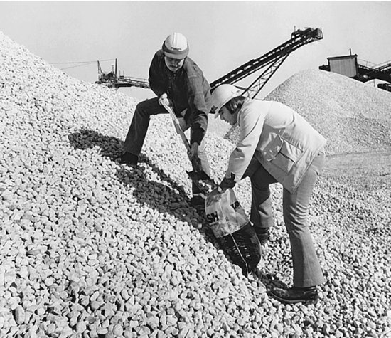
Because aggregates make up roughly three-quarters of the volume of concrete, the strength of a concrete is heavily dependent on the quality of its aggregates. Aggregates for concrete must be strong, clean, resistant to freeze-thaw deterioration, chemically stable, and properly graded for size distribution. An aggregate that is dusty or muddy will contaminate the cement paste with inert particles that weaken it. An aggregate that contains any of a number of chemicals, from sea salt to organic compounds, can cause problems ranging from corrosion of reinforcing steel to retardation of the curing process and weakening of the concrete. A number of standard ASTM laboratory tests are used to assess the various qualities of aggregates (Figure 13.7).
Figure 13.7 Taking a sample of coarse aggregate from a crusher yard for testing. (Reprinted with permission of the Portland Cement Association from Design and Control of Concrete Mixtures, 12th edition; PHOTOS: Portland Cement Association, Skokie, IL.)
Size distribution of aggregate particles is important because a range of sizes must be included and properly proportioned in the concrete mix to achieve close packing of the particles. A concrete aggregate is graded for size using a standard assortment of sieves with diminishing mesh spacings, then weighing the percentage of material that passes through each sieve, in the same manner as described in Chapter 2. Aggregates must also be sized so that the largest particle in the mix is small enough to pass easily between reinforcing bars and fit easily into the formwork. In general, the aggregate should be no larger than three-fourths of the clear spacing between bars or one-third the depth of a slab. For very thin slabs and toppings, a 3/8 -in ch (9-mm) maximum aggregate diameter is often specified. A ¾-inch or 1½-inch (19-mm or 38-mm) maximum size is common for much slab and structural work. Aggregate with diameters up to 6 inches (150 mm) are used in dams and other massive structures.
Lightweight aggregates are used for various special types of concrete. Structural lightweight aggregates are made from minerals such as shale. The shale is crushed to the desired particle sizes, then heated in an oven to a temperature at which it becomes plastic in consistency. The small amount of water that occurs naturally in the shale turns to steam and expands the softened particles like popcorn. Concrete made from this expanded shale aggregate has a density about 25 percent less than that of normal concrete, yet it is nearly as strong. Nonstructural lightweight concretes are made for use in insulating roof toppings that have densities only one-fourth to one-sixth that of normal concrete. The aggregates in these concretes are usually expanded mica (vermiculite ) or expanded volcanic glass (perlite ), both produced by processes much like that used to make expanded shale. However, both of these aggregates are much less dense than expanded shale, and the density of the concretes in which they are used is further reduced by admixtures that entrain large amounts of air during mixing.
ASTM standard C1602 defines the requirements for mixing water for concrete. Generally, water must be free of harmful substances, especially organic material, clay, and salts such as chlorides and sulfates. Water that is suitable for drinking has traditionally been considered suitable for making concrete.
Supplementary Cementitious Materials
Various mineral products, called supplementary cementitious materials (SCMs), may be added to concrete mixtures as a substitute for some portion of the portland cement to achieve a range of benefits. Supplementary cementitious materials are classified as either pozzolans or hydraulic cements.
Pozzolans are materials that react with the calcium hydroxide in wet concrete to form cementing compounds. They include:
- Fly ash, a fine powder that is a waste product from coal-fired power plants, increases concrete strength, decreases permeability, increases sulfate resistance, reduces temperature rise during curing, reduces the amount of mixing water needed, and improves pumpability and workability of concrete. Fly ash also reduces concrete drying shrinkage.
- Silica fume, also known as microsilica, is a powder that is approximately 100 times finer than portland cement, consisting mostly of silicon dioxide. It is a byproduct of electronic semiconductor chip manufacturing. When added to a concrete mix, it produces extremely high-strength concrete that also has very low permeability.
- Natural pozzolans, mostly derived from shales or clays, are used for purposes such as reducing the internal temperature of curing concrete, reducing the reactivity of concrete with aggregates containing sulfates, or improving the workability of concrete. High-reactivity metakaolin is a unique white-colored natural pozzolan that enhances the brilliance of white or colored concrete while also improving the material's workability, strength, and density. These characteristics make it especially well suited as an ingredient in exposed architectural concrete applications where appearance and finish quality are critical.
Blast furnace slag (also called slag cement ), a byproduct of iron manufacture, is a hydraulic cement, meaning that, like portland cement, it reacts directly with water to form a cementitious compound. It may be added to concrete mixes to improve workability, increase strength, reduce permeability, reduce temperature rise during curing, and improve sulfate resistance.
Supplementary cementitious materials may be added to portland cement during the cement manufacturing process, in which case the resulting product is called a blended hydraulic cement (ASTM C595), or they may be added to the concrete mix at the batch plant. The use of SCMs also enhances the sustainability of concrete by reducing reliance on more energy-intensive portland cement and, in many cases, by making productive use of waste products from other industrial manufacturing processes. Half or more of the concrete produced in North America includes some supplementary cementitious materials in its mix.
Admixtures
Ingredients other than cement and other cementitious materials, aggregates, and water, broadly referred to as admixtures, are often added to concrete to alter its properties in various ways:
- Air-entraining admixtures increase the workability of the wet concrete, reduce freeze-thaw damage, and, when used in larger amounts, create very lightweight nonstructural concretes with thermal insulating properties.
- Water-reducing admixtures allow a reduction in the amount of mixing water while retaining the same workability, which results in a higher-strength concrete.
- High-range water-reducing admixtures, also known as superplasticizers, are organic compounds that transform a stiff concrete mix into one that flows freely into the forms. They are used either to facilitate placement of concrete under difficult circumstances or to reduce the water content of a concrete mix so as to increase its strength.
- Accelerating admixtures cause concrete to cure more rapidly, and retarding admixtures slow its curing to allow more time for working with the wet concrete.
- Workability agents improve the plasticity of wet concrete to make it easier to place in forms and finish. They include pozzolans and air-entraining admixtures, along with certain fly ashes and organic compounds.
- Shrinkage-reducing admixtures reduce drying shrinkage and the cracking that results therefrom.
- Corrosion inhibitors are used to reduce rusting of reinforcing steel in structures that are exposed to road deicing salts or other corrosion-causing chemicals.
- Freeze protection admixtures allow concrete to cure satisfactorily at temperatures as low as 20 degrees Fahrenheit (7°C).
- Extended set-control admixtures may be used to delay the curing reaction in concrete for any period up to several days. They include two components: The stabilizer component, added at the time of initial mixing, defers the onset of curing indefinitely; the activator component, added when desired, reinitiates the curing process.
- Coloring agents are dyes and pigments used to alter and control the color of concrete for building components whose appearance is important.
MAKING AND PLACING CONCRETE
The quality of cured concrete is measured by any of several criteria, depending on its end use. For structural columns, beams, and slabs, compressive strength and stiffness are important. For pavings and floor slabs, flatness, surface smoothness, and abrasion resistance are also important. For pavings and exterior concrete walls, a high degree of weather resistance is required. Watertightness is important in concrete tanks, dams, and walls. Regardless of the criterion to which one is working, however, the rules for making high-quality concrete are much the same: Use clean, sound ingredients; mix them in the correct proportions; handle the wet concrete properly; and cure the concrete carefully under controlled conditions.
Proportioning Concrete Mixes
The starting point of any mix design is to establish the desired workability characteristics of the wet concrete, the desired physical properties of the cured concrete, and the acceptable cost of the concrete, keeping in mind that there is no need to spend money to make concrete better than it has to be for a given application. Concretes with ultimate compressive strengths as low as 2000 psi (13.8 MPa) are satisfactory for some foundation elements. At the other extreme, concretes with ultimate compressive strengths of 20,000 psi (140 MPa) and more, produced with the aid of silica fume, fly ash, and superplasticizer admixtures, are used in columns of high-rise buildings. Acceptable workability is achievable at any of these strength levels.
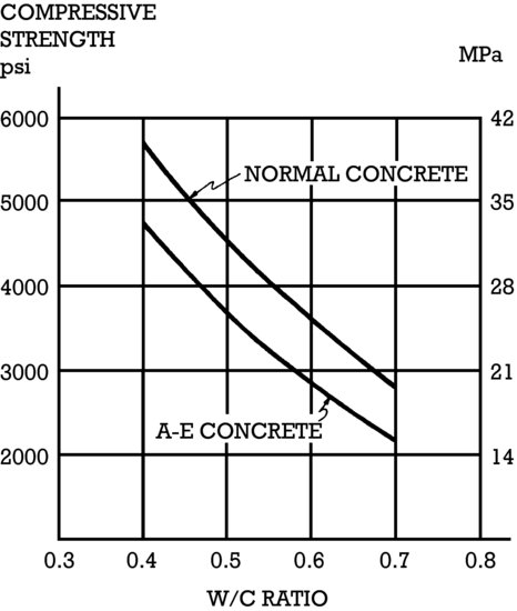
Given a proper gradation of satisfactory aggregates, the strength of cured concrete is primarily dependent on the amount of cement in the mix and on the water–cement (w-c) ratio. Although a proportion of water is required as a reactant in the curing of concrete, much more must be added to give the wet concrete the necessary fluidity and plasticity for placing and finishing. The extra water eventually evaporates from the concrete, leaving microscopic voids that reduce the strength and surface qualities of the concrete (Figure 13.8). For common concrete applications, water–cement ratios range from about 0.45 to 0.60 by weight, meaning that the weight of the water in the mix does not exceed 45 to 60 percent of the weight of the cement. R elatively high water–cement ratios are often favored by concrete workers, because they produce a fluid mixture that is easy to place in the forms, but such a mix may be deficient in strength and surface qualities. Lower water –cement ratios make concrete that is denser and stronger and that shrinks less during curing. However, without air-entraining or water-reducing admixtures, such a mix may not flow easily into the forms or may finish poorly. It is important that concrete be formulated with the right quantity of water for each situation, enough to ensure workability but not enough to adversely affect the properties of the cured material.
Figure 13.8 The effect of the water–cement ratio on the strength of concrete. “A-E concrete” refers to air-entrained concrete. (Reprinted with permission of the Portland Cement Association from Design and Control of Concrete Mixtures, 12th edition; PHOTOS: Portland Cement Association, Skokie, IL.)
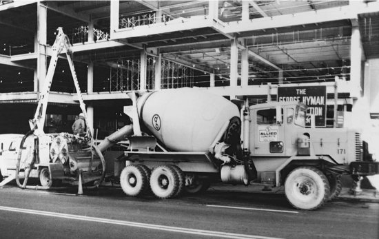
Most concrete in North America is proportioned at central batch plants, using laboratory equipment and engineering knowledge to produce concrete of the proper quality for each project. The concrete is transit mixed en route in a rotating drum on the back of a truck so that it is ready to pour by the time it reaches the job site (Figures 13.9 and 13.10). For very small jobs, concrete may be mixed at the job site, either in a small power-driven mixing drum or on a flat surface with shovels. For these small jobs, where the quality of the finished concrete generally does not have to be precisely controlled, proportioning is usually done by rule of thumb. Typically, the dry ingredients are measured volumetrically, using a shovel as a measuring device, in proportions such as one shovel of cement to two of sand to three of gravel, with enough water to make a wet concrete that is neither soupy nor stiff.
Figure 13.9 Charging a transit-mix truck with measured quantities of cement, aggregates, admixtures, and water at a central batch plant. (Reprinted with permission of the Portland Cement Association from Design and Control of Concrete Mixtures, 12th edition; PHOTOS: Portland Cement Association, Skokie, IL.)
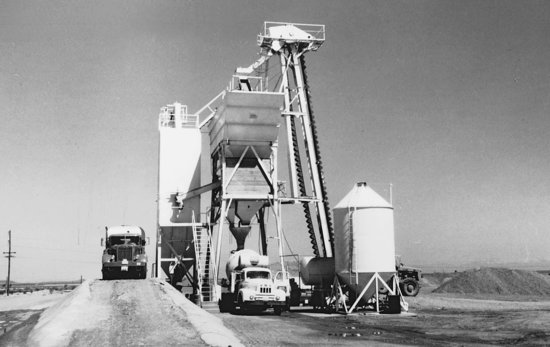
Figure 13.10 A transit-mix truck discharges its concrete, which was mixed en route in the rotating drum, into a truck-mounted concrete pump, which forces it through a hose to the point in the building at which it is being poured. (Reprinted with permission of the Portland Cement Association from Design and Control of Concrete Mixtures, 12th edition; PHOTOS: Portland Cement Association, Skokie, IL.)
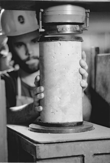
Each load of transit-mixed concrete is delivered with a certificate from the batch plant that lists its ingredients and their proportions. As a further check on quality, a slump test may be performed at the time of pouring to determine if the desired degree of workability has been achieved without making the concrete too wet (Figure 13.11). For structural concrete, standard test cylinders are also poured from each truckload. Within 48 hours of pouring, the cylinders are taken to a testing laboratory, cured for a specified period under standard conditions, and tested for compressive strength (Figure 13.12). If the laboratory results are not up to the required standard, test cores are drilled from the actual members made from the questionable batch of concrete. If the strength of these core samples is also deficient, the contractor may be required to cut out the defective concrete and replace it. Frequently, test cylinders are also cast and cured on the construction site under the same conditions as the concrete in the forms; these may then be tested to determine when the concrete is strong enough to allow removal of forms and temporary supports.
Figure 13.11 Measuring concrete slump. The hollow metal cone is filled with concrete and tamped with the rod according to a standard procedure. The cone is carefully lifted off, allowing the wet concrete to sag, or slump, under its own weight. The slump is then measured in the manner shown (Reprinted with permission of the Portland Cement Association from Design and Control of Concrete Mixtures, 12th edition; PHOTOS: Portland Cement Association, Skokie, IL.)
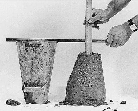
Figure 13.12 Inserting a standard concrete test cylinder into a structural testing machine, where it will be crushed to determine its strength. (Reprinted with permission of the Portland Cement Association from Design and Control of Concrete Mixtures, 12th edition; PHOTOS: Portland Cement Association, Skokie, IL.)
Handling and Placing Concrete
Freshly mixed concrete is not a liquid but a slurry, a semistable mixture of solids suspended in liquid. If it is vibrated excessively, moved horizontally for long distances in the forms, or dropped through constrained spaces, it tends to segregate, which means that the coarse aggregate works its way to the bottom of the form and the water and cement paste rise toward the top. The result is concrete of nonuniform and generally unsatisfactory properties. Segregation is prevented by depositing the concrete, fresh from the mixer, as close to its final position as possible.
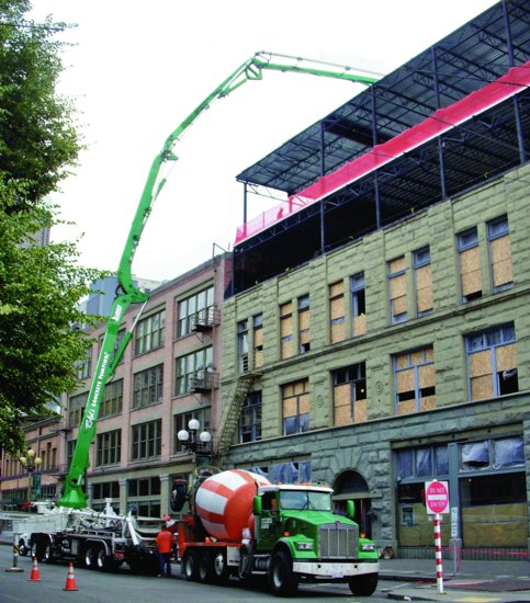
When large quantities of concrete must be placed over a large area or a great height, truck-mounted pumps with extendable booms deliver concrete to its final position (Figure 13.13). Usually, the concrete is pumped through a flexible hose. Or, fixed, rigid pipes may be temporarily installed to carry concrete over unusually long distances. The concrete mixture is designed so that it will not clog the line when it is put under pressure by the pump. Concrete can be pumped to astonishing heights and horizontal distances: For the Burj Khalifa tower in Dubai, concrete was pumped more than 1970 vertical feet (600 m).
Figure 13.13 A transit mixer feeds fresh concrete directly to a truck-mounted pump that delivers the concrete to an upper floor level. The end of the boom is radio controlled by an operator standing close to where the concrete is being deposited. (Photo by Joseph Iano.)
For lesser distance and heights, concrete can be conveyed on portable conveyor belt systems. Crane-mounted buckets (Figure 13.1), powered buggies, or even hand wheelbarrows may also be used. The method selected will depend on the scale of the job and the accessibility of the work to the truck delivering the concrete. To prevent segregation, concrete dropped a distance of more than 3 to 5 feet (1 m or so) should be allowed to fall freely, without obstruction, or it should be deposited through dropchutes that control its fall. Concrete should also not be pushed over horizontal distances from one location to another once it has been deposited.
Once placed, concrete must be consolidated to eliminate trapped air and to completely fill the space around the reinforcing bars and in all corners of the formwork. This may be done by repeatedly thrusting a rod, spade, or immersion-type vibrator into the concrete at closely spaced intervals throughout the formwork. Excessive agitation of the concrete must be avoided, however, or segregation will occur.
Self-consolidating concrete (SCC), a concrete that fills forms completely without requiring vibration or any other method of consolidation, is a more recent development. It is formulated with more fine aggregates than coarse ones, a reversal of the usual proportions; it also includes special superplasticizing admixtures and, in some cases, other viscosity-modifying agents. The result is a concrete that flows freely, yet does not allow its coarse aggregate to sink to the bottom of the mix. Self-consolidating concrete may be used where forms are crowded with steel reinforcing, making consolidation of stiffer conventional concrete problematic. The consistent surface characteristics and crisp edges produced by self-consolidating concrete make it well suited to the production of high-finish-quality architectural concrete. By eliminating the separate consolidation step and allowing more rapid placement, self-consolidating concrete can improve productivity in precast concrete and large-volume sitecast concrete operations. However, formwork costs for self- consolidating concrete may be higher than those for conventional concrete, as the greater fluid pressures exerted by the freely flowing material require stiffer and stronger forms.
Curing Concrete
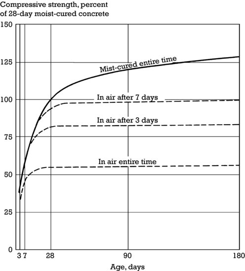
Because concrete cures by hydration, the chemical bonding of the water and cement, and not by simple drying, it is essential that it be kept moist until its required strength is achieved. The curing reaction takes place over a very long period of time, but concrete is commonly designed on the basis of the strength that it reaches after 28 days. If it is allowed to dry out at any point during this time period, the strength of the resulting concrete will be reduced, and its surface hardness and durability can be adversely affected ( Figure 13.14). Concrete cast in formwork is protected from dehydration on most surfaces by the formwork, but the top surfaces must be kept moist by repeatedly spraying or flooding with water, by covering with moisture-resistant sheets of paper or film, or by spraying on a curing compound that seals the surface of the concrete against loss of moisture. These measures are even more important for concrete slabs, whose large exposed surface areas make them especially susceptible to premature drying. This is a particular danger when slabs are poured in hot or windy weather, which can cause the surface of the pour to dry out and crack even before the concrete begins to cure. Temporary windbreaks may be erected, shade may be provided, evaporation retarders may be added to the concrete, and frequent fogging of the air directly over the surface of the slab with a fine spray of water may be required until the slab is hard enough to be finished and covered or sprayed with curing compound.
Figure 13.14 The growth of compressive strength in concrete over time. Moist-cured concrete is still gaining strength after 6 months, whereas air-dried concrete virtually stops gaining strength altogether. (Reprinted with permission of the Portland Cement Association from Design and Control of Concrete Mixtures, 12th edition; PHOTOS: Portland Cement Association, Skokie, IL.)
At low temperatures, the curing reaction in concrete proceeds much more slowly. If concrete reaches subfreezing temperatures while curing, the reaction stops completely until the temperature of the concrete rises above the freezing mark. To achieve full strength, it is important that the concrete be protected from very low temperatures or freezing until it is adequately cured. If freshly poured concrete is covered and insulated, its heat of hydration may be sufficient to maintain an adequate temperature in the concrete even at fairly low air temperatures. Under more severe conditions, the ingredients of the concrete may have to be heated before mixing, and both a temporary enclosure and a temporary source of heat may have to be provided during placing and curing.
In very hot weather, the hydration reaction is greatly accelerated, and concrete may begin curing before there is time to place and finish it. This tendency can be controlled by using cool ingredients and, under extreme conditions, by replacing some of the mixing water with an equal quantity of crushed ice, making sure that the ice has melted fully and the concrete has been thoroughly mixed before placing. Another method of cooling concrete is to bubble liquid nitrogen through the mixture at the batch plant.
FORMWORK
Because concrete is put in place as a shapeless slurry with no physical strength, it must be shaped and supported by formwork until it has cured sufficiently to support itself. Formwork is usually made of braced panels of wood, metal, or plastic. It is constructed as a negative of the shape intended for the concrete. Formwork for a beam or slab serves as a temporary working surface during the construction process and as the temporary means of support for reinforcing bars. Formwork must be strong enough to support the considerable weight and fluid pressure of wet concrete without deflection, which often requires temporary supports that are major structures in themselves. During curing, the formwork helps to retain the necessary water of hydration in the concrete. When curing is complete, the formwork must pull away cleanly from the concrete surfaces without damage either to the concrete or to the formwork, which is usually used repeatedly as a construction project progresses. This means that the formwork should have no reentrant corners that will trap or be trapped by the concrete. Any element of formwork that must be withdrawn directly from a location in which it is surrounded on four or more surfaces by concrete, such as a joist pan (Figures 14.24 and 14.25), must be tapered. Formwork surfaces that are in contact with concrete are also usually coated with a form release compound, an oil, wax, or plastic, that prevents adhesion of the concrete to the form.
The quality of the concrete surfaces can be no better than the quality of the forms in which they are cast, and the requirements for surface quality and structural strength of formwork are rigorous. Top-grade wooden boards and resin-overlaid plywood panels are frequently used to achieve high-quality surfaces. The ties and temporary framing members that support the boards or plywood are spaced closely to avoid bulging of the forms under the high pressure of the wet concrete.
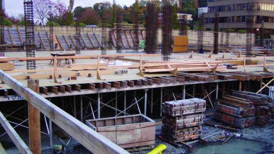
In a sense, formwork constitutes an entire temporary building that must be erected and then demolished in order to produce a second, permanent building of concrete (Figure 13.15). In fact, the cost of conventional formwork accounts for a major portion—often one-half or more—of the overall cost of a concrete building frame. This cost is one of the factors that has led to the development of precasting, a process in which concrete is cast into reusable forms at an industrial plant. Rigid, fully cured structural units from the plant are then transported to the job site, where they are hoisted into place and connected much as if they were structural steel shapes. The alternative to precasting, and the more usual way of building with concrete, is sitecasting, also called cast-in-place construction, in which concrete is poured into forms that are erected on the job site. In Chapters 14 and 15, formwork is shown for both sitecast and precast concrete.
Figure 13.15 Casting concrete on the building site requires the construction of a complete temporary structure that will be removed once the concrete has been placed and cured. (Photo by Joseph Iano.)
REINFORCING
The Concept of Reinforcing
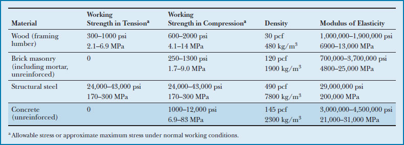
Concrete has no useful tensile strength (Figure 13.16). Historically, its structural uses were limited until the concept of steel reinforcing was developed. The compatibility of steel and concrete is a fortuitous accident. If the two materials had grossly different coefficients of thermal expansion, a reinforced concrete structure would tear itself apart during seasonal cycles of temperature variation. If the two materials were chemically incompatible, the steel would corrode or the concrete would be degraded. If concrete did not adhere to steel, a very different and more expensive configuration of reinforcing would be necessary. Concrete and steel, however, change dimension at nearly the same rate in response to temperature changes; steel is protected from corrosion by the alkaline chemistry of concrete; and concrete bonds strongly to steel, providing a convenient means of adapting brittle concrete to structural elements that must resist not only compression, but tension, shear, and bending as well.
Figure 13.16 Comparative physical properties of four common structural materials: wood, brick masonry, steel, and concrete (shaded row). Concrete, like masonry, has no useful tensile strength, but its compressive strength is considerable, and when combined with steel reinforcing, it can be used for every type of structure. The ranges of values in strength and stiffness reflect variations in concrete mix properties. (Specially formulated concretes are capable of substantially higher strengths than those listed in this table.)
The basic theory of reinforced concrete is extremely simple: Put the reinforcing steel where there are tensile (stretching) forces in a structural member, and let the concrete resist the compression (squeezing) forces. This accounts fairly precisely for the location of most of the reinforcing steel that is used in a concrete structure. However, there are some important exceptions: Steel is used to resist a share of the compression in concrete columns and in beams whose height must be reduced for architectural reasons. It is used as column ties, discussed later in this chapter, to prevent buckling of vertical reinforcing in columns. It is used to resist cracking that might otherwise be caused by curing shrinkage, and by thermal expansion and contraction in slabs and walls.
Steel Bars for Concrete Reinforcement
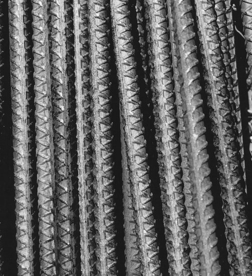
Steel reinforcing bars (rebar) for concrete construction are hot-rolled in much the same way as structural shapes. They are round in cross section and deformed with surface ribs for better bonding to concrete ( Figures 13.17 and 13.18). At the end of the rolling line in the mill, the bars are cut to a standard length (commonly 60 feet, or 18.3 m, in the United States), bundled, and shipped to local fabricating shops.
Figure 13.17 Glowing strands of steel are reduced to reinforcing bars as they snake their way through a rolling mill. (Courtesy of Bethlehem Steel Corporation.)
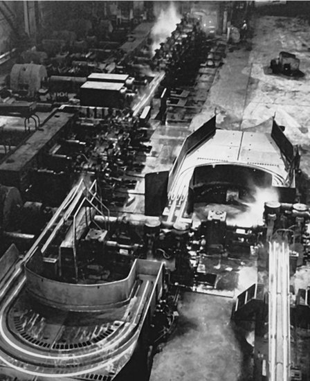
Figure 13.18 The deformations rolled onto the surface of a reinforcing bar help it to bond tightly to concrete. (Photo by Edward Allen.)
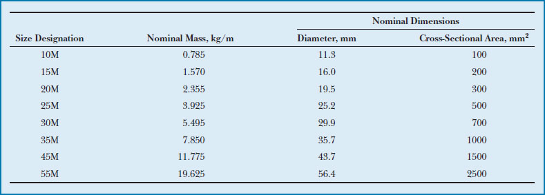
Reinforcing bars are rolled in standard diameters. In the United States, bars are specified by a number that corresponds to eighths of an inch (3.2 mm) of bar diameter (Figure 13.19). For example, a number 6 reinforcing bar is 6/8 or ¾ inch (19 mm) in diameter, and a number 8 is 8/8 or 1 inch (25.4 mm) in diameter. Bars larger than number 8 vary slightly from these nominal diameters in order to correspond to convenient cross-sectional areas. For the increasing volume of work in the United States that is carried out in SI units, a soft conversion of units is used: The bars are exactly the same, but a different numbering system is used, corresponding roughly to the diameter of each bar in millimeters. This avoids the expensive process of converting rolling mills to produce a slightly different set of bar sizes. In most countries other than the United States, a hard metric range of reinforcing bar sizes is standard (Figure 13.20).
Figure 13.19 American standard sizes of reinforcing bars. These sizes were originally established in conventional units of inches and square inches. More recently, “soft metric” designations have also been given to the bars without changing their sizes. Notice that the size designations of the bars in both systems of measurement correspond very closely to the rule-of-thumb values of 1/8 inch or 1 mm per bar size number.
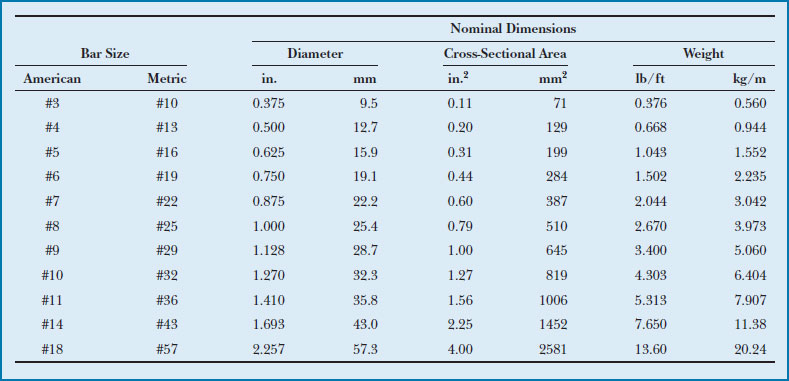
Figure 13.20 These hard metric reinforcing bar sizes are used in most countries of the world.
In selecting reinforcing bars for a given beam or column, the structural engineer knows from calculations the required cross-sectional area of steel that is needed in a given location. This area may be achieved with a larger number of smaller bars, or a smaller number of larger bars, in any of several combinations. The final bar arrangement is based on the physical space available in the concrete member, the required depth of concrete that must cover the reinforcing, the clear spacing required between bars to allow passage of the concrete aggregate, and the sizes and number of bars that will be most convenient to fabricate and install.
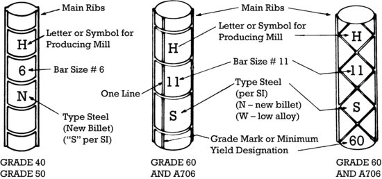
Most reinforcing bars are manufactured according to ASTM standard A615 and are available in grades 40, 60, and 75, corresponding to steel with yield strengths of 40,000, 60,000, and 75,000 psi (280, 420, and 520 MP a), respectively (Figure 13.21). Grade 60 is generally the most economical and readily available of the three, although grade 75 is finding increasing use in column reinforcing. Reinforcing bars conforming to ASTM A706, made with low-alloy steel meeting special ductility requirements, are used where concrete structures must meet special seismic design criteria or where extensive welding of reinforcing is required. In structures with especially heavy reinforcing requirements, reinforcing bars conforming to ASTM A1035, with strengths as high as 120,000 psi ( 830 MP a), may be used. With such high-strength bars, bar size may be reduced and the spacing between the bars may be increased in comparison to designs with conventional-strength reinforcing. This reduces rebar congestion, making it easier to place and consolidate the concrete around the reinforcing.
Figure 13.21 Reinforcing bars are manufactured with identification marks, denoting the mill that produced the bars, bar size, type of steel, and steel grade. Steel grade is indicated either with a number, such as “60” for Grade 60 steel, or with short bars (grade lines), in which no bars indicates Grade 40 or 50 steel, one bar indicates Grade 60 steel, and two bars indicates grade 75 steel. (Courtesy of Concrete Reinforcing Steel Institute.)
Reinforcing bars in concrete structures that are exposed to salts such as deicing salts or those in seawater are prone to rust. Galvanized reinforcing bars and epoxy-coated reinforcing bars are often used in marine structures, highway structures, and parking garages to resist this corrosion. Stainless steel bars, stainless-steel-clad bars, zinc-and-polymer-coated bars, and proprietary corrosion-resistant alloy bars are newer types of corrosion-resistant reinforcing. Still in the experimental stage or newest to market are nonmetallic reinforcing bars made from high-strength fibers of carbon, aramid, or glass embedded in a polymeric matrix.
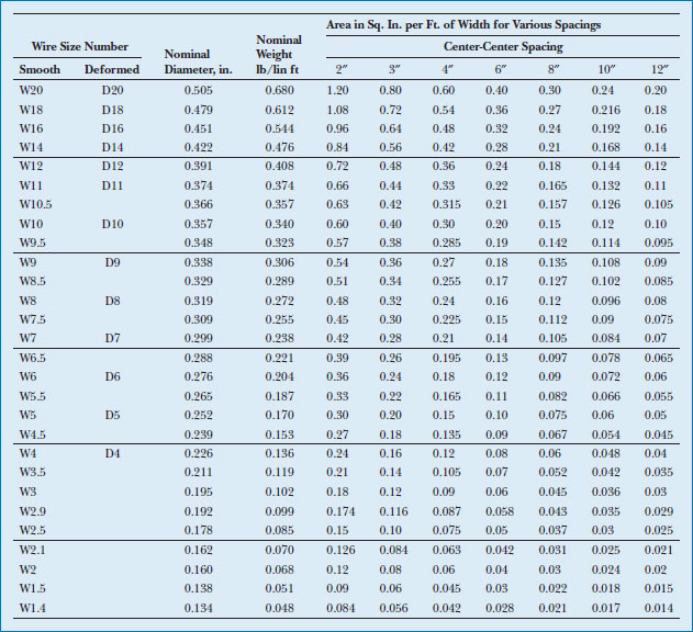
As an alternative to conventional reinforcing bars, reinforcing steel for slabs is produced in sheets or rolls of welded wire reinforcing (WWR), also called welded wire fabric (WWF), a grid of wires or round bars spaced 2 to 12 inches (50–300 mm) apart ( Figure 13.22). The lighter styles of welded wire fabric resemble cattle fencing and are used to reinforce concrete slabs on grade and certain precast concrete elements. The heavier styles find use in concrete walls and structural slabs. The principal advantage of welded wire fabric over individual bars is economy of labor in placing the reinforcing, especially where a large number of small bars can be replaced by a single sheet of material. The size and spacing of the wires or bars for a particular application are specified by the structural engineer or architect of the building.
Figure 13.22 Standard configurations of welded wire reinforcing. The heaviest “wires” are more than ½ inch (13 mm) in diameter, making them suitable for structural slab reinforcing. Welded wire reinforcing is specified by first indicating the spacing of the wires and then the wire types. For example, the designation 6 × 12-W12 × W5 indicates welded wire reinforcing with W12 longitudinal wires spaced at 6 inches (150 mm) and W5 transverse wires spaced at 12 inches (300 mm). (Courtesy of Concrete Reinforcing Steel Institute.)
Fabrication and Erection of Reinforcing Bars
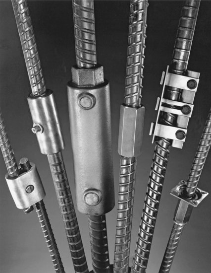
The fabrication of reinforcing steel for a concrete construction project is analogous to the fabrication of steel shapes for a steel frame building (Chapter 11). The fabricator receives the engineering drawings for the building from the contractor and prepares shop drawings for the reinforcing bars. After the shop drawings have been checked by the engineer or architect, the fabricator sets to work cutting the reinforcing bar stock to length, making the necessary bends (Figure 13.23) and tying the fabricated bars into bundles that are tagged to indicate their destination in the building. The bundles are shipped to the building site as needed. There they are broken down, lifted by hand or hoisted by crane, and wired (or occasionally welded) together in the forms to await pouring of the concrete. The wire has a temporary function only, which is to hold the reinforcement in position until the concrete has cured. Any transfer of load from one reinforcing bar to another in the completed building is done by the concrete. Where two bars must be spliced, they are overlapped a specified number of bar diameters (typically 30), and the loads are transferred from one to the other by the surrounding concrete. The one common exception occurs in heavily reinforced columns where there is insufficient space to overlap the bars; there they are often spliced end to end rather than overlapped, and loads are transferred through welds or sleevelike mechanical splicing devices (Figure 13.24).
Figure 13.23 The bending of reinforcing bars is done according to precise standards in a fabricator's shop. (Courtesy of Concrete Reinforcing Steel Institute.) You can download a PDF of this figure at http://www.wiley.com/go/aflblce6ne.
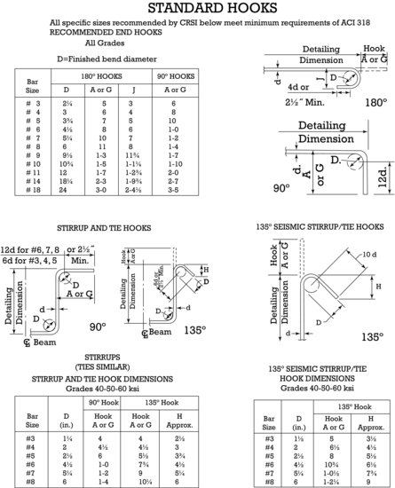
Figure 13.24 Some mechanical devices for splicing reinforcing bars. From left to right: A lapped, wedged connection, used primarily to connect new bars to old ones when adding to an existing structure. A welded connector, very strong and tough. A grouted sleeve connector for joining precast concrete components: One bar is threaded and screwed into a collar at one end of the sleeve, and the other bar is inserted into the remainder of the sleeve and held there with injected grout. A threaded sleeve, with both bars threaded and screwed into the ends of the sleeve. A simple clamping sleeve that serves to align compression bars in a column. A flanged coupler for splicing bars at the face of a concrete wall or beam: The coupler is screwed onto the threaded end of one bar, and its flange is nailed to the inside face of the formwork. After the formwork has been stripped, the other bar is threaded and screwed through a hole in the flange and into the coupler. (Photo courtesy of ERICO, Inc.)
The combined action of concrete and steel in reinforced concrete structural elements is such that the reinforcing steel is usually loaded axially in tension or compression, and occasionally in shear, but never in bending. The bending stiffness of the reinforcing bars themselves is of no consequence in imparting strength to the concrete.
Reinforcing a Simple Concrete Beam
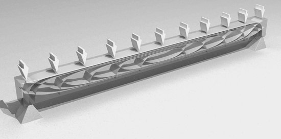
In an ideal, simply supported beam under uniform loading, compressive (squeezing) forces follow a set of archlike curves that create a maximum stress in the top of the beam at midspan, with progressively lower compressive stresses toward either end. A mirrored set of curves correspond to paths of tensile (stretching) force, with stresses again reaching a maximum at the middle of the span (Figure 13.25). In an ideally reinforced concrete beam, steel reinforcing bars would be bent to follow these lines of tension, and the bunching of the bars at midspan would serve to resist the higher stresses at that point. It is difficult, however, to bend bars into these curves and to support the curved bars adequately in the formwork, so a simpler rectilinear arrangement of reinforcing steel is substituted.
Figure 13.25 (a) The directions of force in a simply supported beam (supported only at its ends) under uniform loading. The archlike lines represent compression, and the cablelike lines represent tension. Near the ends of the beam, the lines of strongest tensile force move upward diagonally through the beam. (b) Steel reinforcing for the same simply supported beam. The concrete resists compressive forces. The horizontal bars near the bottom of the beam resist the tensile forces. The vertical stirrups resist the lesser diagonal tensile forces near the ends of the beam.

(a)
(b)
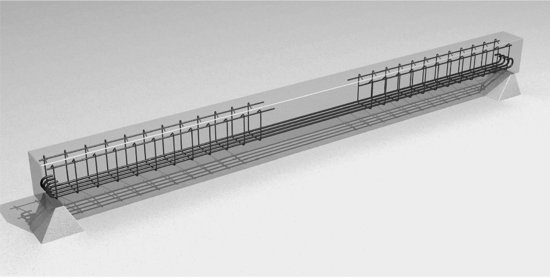
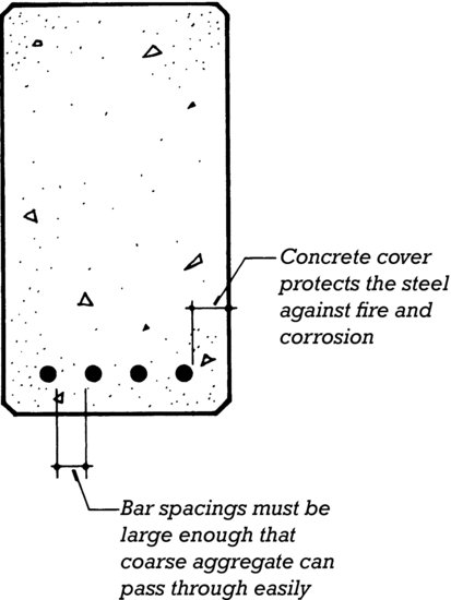
This arrangement consists of a set of bottom bars and stirrups. The bottom bars are placed horizontally near the bottom of the beam, leaving a specified amount of concrete below and to the sides of the rods as cover (Figure 13.26). The concrete cover provides a full embedment for the reinforcing bars and protects them against fire and corrosion. The bars are most heavily stressed at the midpoint of the beam span, with progressively smaller amounts of stress toward each of the supports. The differences in stress are dissipated from the bars into the concrete by means of bond forces, the adhesive forces between the concrete and the steel, aided by the ribs on the surface of the bars. At the ends of the beam, some stress remains in the steel, but there is no further length of concrete into which the stress can be dissipated. This problem is solved by bending the ends of the bars into hooks, which are semicircular bends of standard dimensions.
Figure 13.26 A cross section of a rectangular concrete beam showing cover and bar spacing.
The bottom bars do the heavy tensile work in the beam, but some lesser tensile forces occur in a diagonal orientation near the ends of the beam. These are resisted by a series of stirrups (Figure 13.25). The stirrups may be either open U-stirrups, as shown in Figure 13.25, or closed stirrup-ties, which are full rectangular loops of steel that wrap all the way around the longitudinal bars. U- stirrups are less expensive to make and install and are sufficient for many situations, but stirrup-ties are required in beams that will be subjected to torsional (twisting) forces or to high compressive forces in the top or bottom bars. In either case, the stirrups furnish vertical tensile reinforcing to resist the cracking forces that run diagonally across them. A more efficient use of steel would be to use diagonal stirrups oriented in the same direction as the diagonal tensile forces, but they would be difficult to install.
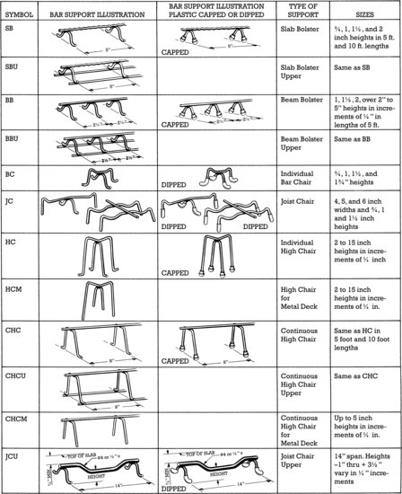
When the simple beam of our example is formed, the bottom steel is supported at the correct cover height by chairs made of heavy steel wire or plastic (Figures 13.27 and 13.28). In a broad beam or slab, bars are supported by long chairs called bolsters. Chairs and bolsters remain in the concrete after pouring, even though their work is finished, because there is no way to get them out. In outdoor concrete work, the feet of the chairs and bolsters sometimes rust where they come in contact with the face of the beam or slab unless plastic or plastic-capped steel chairs are used. Where reinforced concrete is poured in direct contact with the soil, concrete bricks or small pieces of concrete may be used to support the bars instead of chairs, to avoid the possibility of rust forming under the feet of the metal chairs and spreading up into the reinforcing bars.
Figure 13.27 A two-piece plastic bar support, called a “tower chair,” supports a steel reinforcing bar for a structural concrete slab. To the left of the chair, a small concrete brick supporting a second bar in a position closer to the bottom of the slab is also partially visible. (Photo by Joseph Iano.)
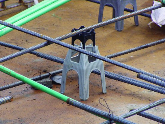
Figure 13.28 Chairs and bolsters for supporting reinforcing bars in beams and slabs. Bolsters and continuous chairs are made in long lengths for use in slabs. Chairs support only one or two bars each. (Courtesy of Concrete Reinforcing Steel Institute.) You can download a PDF of this figure at http://www.wiley.com/go/aflblce6ne.
The stirrups in the simple beam that we have been examining are supported by wiring them to the bottom bars and by tying their tops to horizontal #3 top bars (the smallest standard size) that have no function in the beam other than to keep the stirrups upright and properly spaced until the concrete has been poured and cured.
Reinforcing a Continuous Concrete Beam
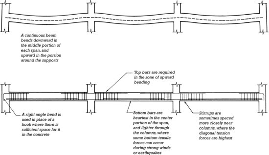
Most sitecast concrete beams are not of this simple type, because concrete lends itself most easily to one-piece structural frames with a high degree of continuity from one beam span to the next. In a continuous beam, the bottom of the beam is in tension at midspan, and the top of the beam is in tension at points of support (such as at girders, columns, or walls). This means that top bars must be provided over the supports, and bottom bars in midspan, along with the usual stirrups, as illustrated in Figure 13.29.
Figure 13.29 Reinforcing for a continuous beam that is supported across several spans. The upper diagram shows in exaggerated form the shape taken by a continuous beam under uniform loading; the broken line is the centerline of the beam. The lower diagram shows the arrangement of bottom steel, top steel, and stirrups conventionally used in this beam. The bottom bars are usually placed on the same level, but they are shown on two levels in this diagram to demonstrate the way in which some of the bottom steel is discontinued in the zones near the columns. There is a simple rule of thumb for determining where the bending steel must be placed in a beam: Draw an exaggerated diagram of the shape the beam will take under load, as in the top drawing of this illustration, and put the bars as close as possible to the convex edges.
Reinforcing Structural Concrete Slabs
A concrete slab that spans across parallel beams or walls (one-way action ) is, in effect, a very wide beam. The reinforcing pattern for such a slab is similar to the reinforcing pattern in a beam, but with a larger number of smaller top and bottom bars distributed evenly across the width of the slab. Because the slab is wide, it has a large cross-sectional area of concrete that can usually resist the relatively weak diagonal tension forces near its supports without the aid of stirrups.
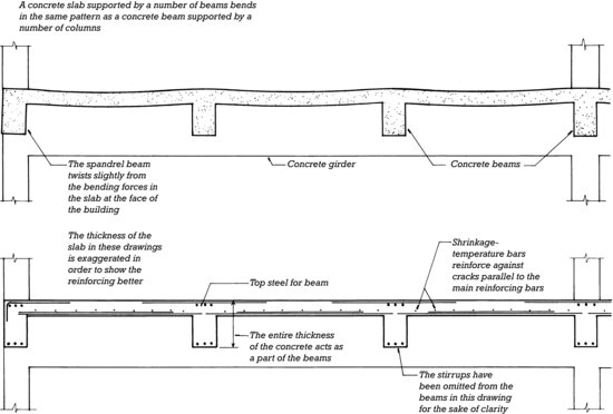
One-way slabs must be provided with shrinkage–temperature steel, a set of small-diameter reinforcing bars set at right angles to, and on top of, the primary reinforcing in the slab. Their function is to prevent cracks from forming parallel to the primary reinforcing because of concrete shrinkage, temperature-induced stresses, or miscellaneous forces that may occur in the building (Figure 13.30).
Figure 13.30 Reinforcing for a one-way concrete slab. The reinforcing is similar to that for a continuous beam, except that stirrups are not usually required in the slab, and shrinkage–temperature bars must be added in the perpendicular direction. The slab does not sit on the beams; rather, the concrete around the top of a beam is part of both the beam and the slab. A concrete beam in this situation is considered to be a T-shaped member, with a portion of the slab acting together with the stem of the beam, resulting in greater structural efficiency and reduced beam depth.
Two-Way Slab Action
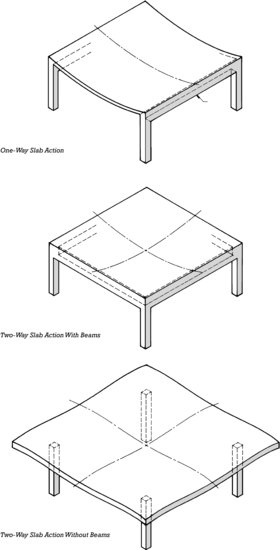
A structural economy mostly unique to concrete frames is realized through the use of two-way action in floor and roof slabs. Two-way slabs, which work best for bays that are square or nearly square, are reinforced equally in both directions and share the bending forces equally between the two directions. In comparison to equivalent one-way slabs, two-way slabs can be somewhat shallower, use less reinforcing steel, and cost less. Figure 13.31 illustrates the concept of two-way action. Several different two-way concrete framing systems will be shown in detail in Chapter 14.
Figure 13.31 One-way and two-way slab action, with deflections greatly exaggerated.
The country . . . near Taliesin, my home and workshop, is the bed of an ancient glacier drift. Vast busy gravel pits abound there, exposing heaps of yellow aggregate once and still everywhere near, sleeping beneath the green fields. Great heaps, clean and golden, are always waiting there in the sun. And I never pass . . . without an emotion, a vision of the long dust-whitened stretches of the cement mills grinding to impalpable fineness the magic powder that would “set” my vision all to shape; I wish both mill and gravel endlessly subject to my will. . . . Materials! What a resource.
—Frank Lloyd Wright, in Architectural Record, October 1928
Reinforcing Concrete Columns
Columns contain two types of reinforcing: Vertical bars (also called column bars ) are large-diameter bars that share the compressive loads with the concrete, resist tensile stresses that may occur in columns, and impart ductility to the column (important for resistance to earthquake forces). Ties of small-diameter steel bars wrapped around the vertical bars help to prevent them from buckling under load: Inward buckling is prevented by the concrete core of the column and outward buckling by the ties (Figure 13.32). The vertical bars may be arranged in either circular or rectangular patterns. The ties may be either of two types: column spirals or column ties.
Figure 13.32 Reinforcing for concrete columns. To the left is a column with a rectangular arrangement of vertical bars and column ties. To the right is a circular arrangement of vertical bars with a column spiral. Regardless of the bar and tie arrangements, the outer form of the column can be cast round or square.
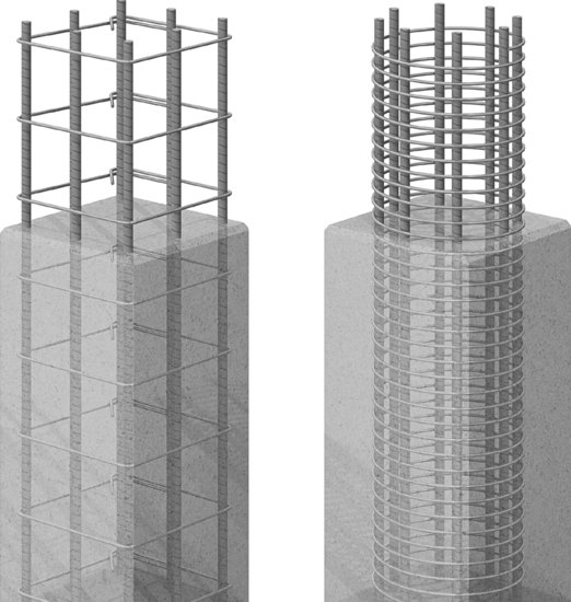
Column spirals are shipped to the construction site as tight coils of rod that are expanded accordion fashion to the required spacing and wired to the vertical bars. The vertical bars must be in a circular (or four-square) arrangement so as to make contact with the spiral. The outer form of the column, though, can be circular or rectangular. By overlapping spirals, even long lines of vertical bars in a reinforced wall can be tied with spirals.
Column ties are discrete, closely spaced hoops, individually wired in place. They are used mostly to tie rectangular arrangements of vertical bars. A single column tie can effectively restrain four vertical bars, one at each bent corner of the tie. For columns with more than four bars, additional ties are added to provide restraint for the bars between corners (Figure 13.33).
Figure 13.33 Rectangular column cages, fabricated off-site, arrive on the construction site on a flatbed trailer. The vertical bars are tied with column ties. Note the added ties used to capture bars between corners. Each cage is tagged to identify its intended location in the building frame. (Photo by Joseph Iano.)

A circular arrangement of vertical bars is often more economical than a rectangular one because it avoids the need for added ties to capture bars between corners. However, column ties are generally more economical than spirals, so even columns with circular bar arrangements may be tied with discrete, circular ties. However, spiral-tied columns are more effective at resisting extreme dynamic loads, such as occur during earthquakes. To minimize labor costs, column reinforcing may be wired together while lying on the ground, and the finished column cage lifted into final position by crane (Figure 13.34). Or, column cages may be assembled in the reinforcing fabricator's shop, and delivered ready for installation to the construction site (Figure 13.33).
Figure 13.34 A large reinforcing cage being assembled while resting on its side. Once complete, it will be lifted into final position, where it will form part of the central core structure of a tall building. Note the large rectangular ties. The worker standing on top of the reinforcing cage is installing shorter ties between pairs of column bars. Additional ties are stacked toward the back, right-hand side of the top of the cage (Photo by Joseph Iano.)

Fibrous Reinforcing
Fibrous reinforcing is composed of short fibers of glass, steel, or polypropylene that are added to the concrete mix. Microfiber reinforcing is added in relatively low dosages and is intended to reduce plastic shrinkage cracking, which frequently occurs while the concrete is still in a plastic state, during the earliest stages of curing. Microfiber reinforcing makes little if any contribution to the properties of fully cured concrete. Macrofiber reinforcing, usually of polypropylene or a steel-polypropylene blend, not only protects against plastic shrinkage but also resists long-term cracking due to drying shrinkage and thermal stresses. Macrofiber reinforcing is added to concrete at dosages 10 or 20 times greater than those of microfiber reinforcing and, in some cases, fully replaces the usual shrinkage–temperature steel in concrete slabs. Macrofiber reinforcing can also improve concrete's resistance to impact, abrasion, and shock. Glass fibers are also added to concrete to produce glass-fiber-reinforced concrete (GFRC), which is used for cladding panels (see Chapter 20).
CONCRETE CREEP
In addition to plastic and drying shrinkage, concrete is subject to long-term creep. When placed under sustained compressive stress from its own weight, the weight of other permanent building components, or the force of prestressing (as described later in this chapter), concrete will gradually and permanently shorten over a period of months or years. In some circumstances, this dimensional change is of sufficient magnitude that it must be accounted for in the design and detailing of other parts. For example, when a brick veneer cladding system is supported on a concrete building frame, the shrinkage of the concrete combined with other factors affecting movement of the masonry require that horizontal movement joints be designed into the cladding system to accommodate the differential movement between the cladding and the supporting structure. If these joints are not provided, or if they are too narrow and unable to accommodate the extent of movement, the cladding system can fail as it becomes compressed, in part, by the shortening of the concrete structure. As a rule of thumb, sitecast concrete building frames can be expected to shorten in height under the influence of their own weight and other dead loads at the rate of  inch for every 10 feet (½ mm per meter) of building height.
PRESTRESSING
When a beam supports a load, the compression side of the beam is squeezed slightly and the tension side is stretched. In a reinforced concrete beam, the stretching tendency is resisted by the reinforcing steel but not by the concrete. When the steel elongates under tension, the concrete around it forms cracks that run from the edge of the beam to the horizontal plane in the beam, above which compressive forces occur. This cracking is even visible to the unaided eye in reinforced concrete beams that are loaded to (or beyond) their full capacity. In effect, more than half of the concrete in the beam is doing no useful work except to hold the steel in position and protect it from fire and corrosion (Figure 13.35, top).
Figure 13.35 The rationale for prestressing concrete. In addition to the elimination of cracks in the prestressed beam, the structural action is more efficient than that of a reinforced beam. Therefore, the prestressed beam uses less material. The small diagrams to the right indicate the distribution of stresses across the vertical cross section of each of the beams at midspan.
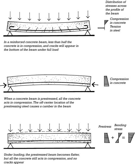
If the reinforcing bars could be stretched to a high tension before the beam is loaded and then released against the concrete that surrounds them, they would place the concrete in compression. If a load were subsequently put on the beam, the tension in the stretched steel would increase further, and the compression in the concrete surrounding the steel would diminish. If the initial tension or prestress in the steel bars were of sufficient magnitude, however, the surrounding concrete would never be subjected to tension, and no cracking would occur. Furthermore, the beam would be capable of carrying a greater load with the same amounts of concrete and steel than if it were merely reinforced in the conventional manner. This is the rationale for prestressed concrete. Prestressed members, particularly those designed to work in bending, contain less concrete than reinforced members of equivalent strength. Their lighter weight also pays off by making precast, prestressed concrete members easier and cheaper to transport. For this reason, structural precast concrete used for slabs, beams, and girders (and in some cases columns as well) is usually prestressed.
In practice, ordinary reinforcing bars are not sufficiently strong to serve as prestressing steel. Prestressing is practical only with very high-strength steel strands that are manufactured for the purpose. These are made of cold-drawn steel wires that are formed into small-diameter cables.
Pretensioning
Prestressing is accomplished in two different ways. Pretensioning is used with precast concrete members: High-strength steel strands are stretched tightly between abutments in a precasting plant before the concrete is cast. The concrete member (or, more commonly, a series of concrete members arranged end to end) is then cast around the stretched steel (Figure 15.8). The curing concrete adheres to the strands along their entire length. After the concrete has cured to a specified minimum compressive strength, the strands are cut off at either end of each member. This releases the external tension on the steel, allowing it to recoil slightly, which squeezes all of the concrete of the member into compression. If, as is usually the case, the steel is placed as close as possible to the tension side of the member, the member takes on a decided camber (lengthwise arching) at the time the steel strands are cut (Figure 13.36). Much or all of this camber disappears later when the member is subjected to loads in a building.
Figure 13.36 Pretensioning. Photographs of pretensioned steel strands for a beam are shown in Chapter 15.
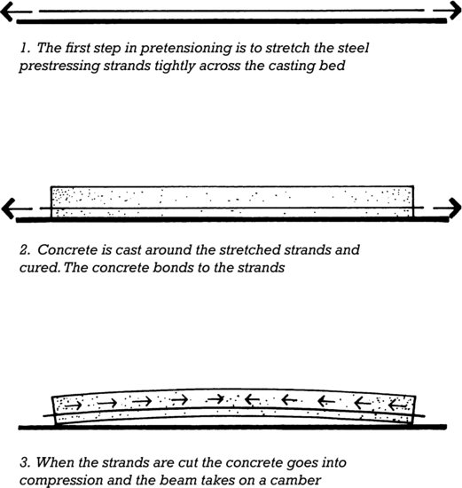
The strong abutments needed to hold the tensioned strands prior to the pouring of concrete are very expensive to construct except in a single fixed location where many concrete members can be created within the same set of abutments. For this reason, pretensioning is useful only for concrete members cast in precasting plants.
Posttensioning
Unlike pretensioning, posttensioning is done almost exclusively in place on the building site. High-strength steel strands (called tendons ) are covered with a steel or plastic tube to prevent them from bonding to the concrete and are not tensioned until the concrete is poured and has achieved adequate strength. Each tendon is anchored to a steel plate embedded in one end of the beam or slab. A hydraulic jack is inserted between the other end of the tendon and a similar steel plate in the other end of the member. The jack applies a large tensile force to the tendon while compressing the concrete with an equal but opposite force that is applied through the plate. The stretched tendon is anchored to the plate at the second end of the member before the jack is removed (Figures 13.37, 13.38, and 13.39). For very long members, the tendons are jacked from both ends to be sure that frictional losses in the tubes do not prevent uniform tensioning.
Figure 13.37 Posttensioning, using draped strands to more nearly approximate the flow path of tensile forces in the beam.
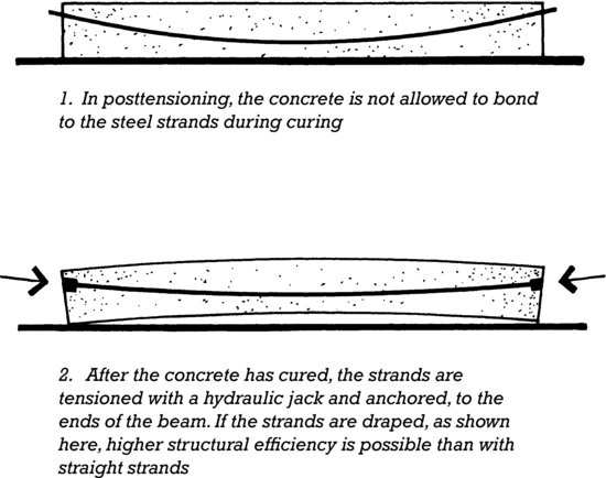
Figure 13.38 Posttensioning draped tendons in a large concrete beam with a hydraulic jack. Each tendon consists of a number of individual high-strength steel strands. The bent bars projecting from the top of the beam will be embedded in the concrete slab that the beam will support to allow them to act together as a composite structure. (Reprinted with permission of the Portland Cement Association from Design and Control of Concrete Mixtures, 12th edition; PHOTOS: Portland Cement Association, Skokie, IL.)
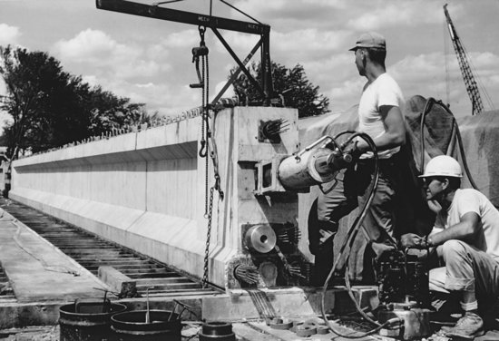
Figure 13.39 Most beams and slabs in buildings are posttensioned with plastic-sheathed, unbonded tendons. The pump and hydraulic jack (also called a ram) are small and portable. (Courtesy of Constructive Services, Inc., Dedham, MA.)
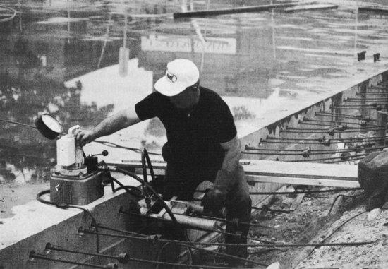
The net effect of posttensioning is the same as that of pretensioning. The difference is that in posttensioning, abutments are not needed because the member itself provides the opposing force needed to tension the steel. When the posttensioning process is complete, the tendons may be left unbonded, or, if they are in a steel tube, they may be bonded by injecting grout to fill the space between the tendons and the tube. Bonded construction is common in bridges and other heavy structures, but most posttensioning in buildings is done with unbonded tendons. These are made up of cold-drawn steel wires and are roughly ½ inch ( 13 m m) in diameter (Figures 13.39 and 13.40). The tendon is coated with a lubricant and covered with a plastic sheath at the factory.
Figure 13.40 End anchorage for a posttensioning tendon. The steel anchor plate and plastic pocket former are cast into the edge of the concrete slab. After the concrete has cured, the formwork and pocket former are removed, exposing the anchor plate. The two conical wedges are inserted around the tendon and into the hole in the anchor plate. The ram presses against the wedges and draws the tendon through until the gauge on the pump indicates that the required tension has been reached. When the ram is withdrawn, the wedges are drawn into the conical hole, grip the tendon, and maintain the tension. After all the tendons have been tensioned, the excess lengths of tendon are cut off and the pockets grouted flush with the edge of the slab. (Photo by Edward Allen.)
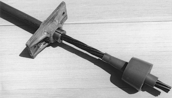
Even higher structural efficiencies are possible in a prestressed beam or slab if the steel strands are placed to follow as closely as possible the lines of tensile force that are diagrammed in Figure 13.25. In a posttensioned beam or slab, this is done by using chairs of varying heights to support the tendons along a curving line that closely follows the center of the tensile forces in the member. Such a tendon is referred to as being draped (Figure 13.41). Draping is impractical in pretensioned members because the tendons would have to be pulled down at many points along their length. But pretensioned strands can be harped, that is, pulled up and down in the formwork to make a downward -pointing or flattened V shape in each member that approximates very roughly the shape of a draped tendon (Figures 13.42 and 15.9).
Figure 13.41 Draped posttensioning tendons. As explained in Chapter 14, banded tendons run from lower left to upper right and distributed tendons run in the perpendicular orientation. (Photo by Joseph Iano.)

Figure 13.42 Shaping pretensioning strands to improve structural efficiency. Examples of depressed and harped strands are shown in Chapter 15.
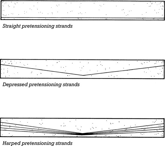
Because it is always highly compressed by prestressing force, the concrete in a prestressed member is subject to creep. The steel strands also stretch slightly over time and lose some of their prestressing force. Initial prestressing forces must be increased slightly above their optimal values to make up for these long-term changes. Further increases in initial tension are needed to accommodate the slight curing shrinkage that takes place in concrete, small, short-term movements caused by elastic shortening of the concrete during structural loading, and frictional losses and initial slippage or set of the strand anchors in posttensioned members.
Succeeding chapters will discuss prestressed concrete, both pretensioned and posttensioned, in greater detail, showing its application to various standard precast and cast-in-place systems of construction.
ACI 301
In North America, concrete structures are built according to the requirements of ACI 301: Specifications for Structural Concrete for Buildings, a publication of the American Concrete Institute. This comprehensive document covers every aspect of concrete work: formwork, reinforcement, chairs and bolsters, concrete mixtures, handling and placing of concrete, lightweight concrete, prestressing, and the use of concrete in exposed architectural surfaces. It is a standard that is familiar to architects, engineers, contractors, and building inspectors, and it furnishes the common basis for everyone who works in designing and constructing a concrete building.
INNOVATIONS IN CONCRETE CONSTRUCTION
The basic materials, concrete and steel, are constantly undergoing research and development, leading to higher allowable strengths and decreased weight of structures. Structural lightweight concretes are being used more widely to reduce dead loads. Shrinkage-compensating cements have been developed for use in concrete structures that cannot be allowed to shrink during curing. Self-consolidating concrete is being used to improve productivity and reduce labor costs. Improved coatings for reinforcing steel, steel alloys with greater corrosion resistance, and nonmetallic reinforcing are being used to extend the life of structures exposed to the weather, marine environments, and road salts.
Concretes with compressive strengths as high as 30,000 psi ( 200 MPa ) and that exhibit even usable tensile strength are called ultra-high performance concretes (UHPCs). They are formulated from portland cement, silica fume, silica or quartz flour (extremely finely ground silica or quartz), fine sand, high-range water reducer, water, and steel fibrous reinforcing. There is no large aggregate. The resulting concrete is characterized by a dense packing of the fine aggregate and finely ground mineral powders within the cement matrix, resulting in concrete that is stronger, less permeable, and more durable than conventional high-strength mixes. The addition of steel macrofiber reinforcing imparts tensile strength and ductility (toughness). Ultra-high performance concrete can be used in the casting of remarkably thin architectural elements. Precast exterior cladding panels and arched canopies, for example, both no thicker than ¾ inch (20 mm) and with no conventional reinforcing, have been produced from this material (Figures 13.43 and 13.44). Ultra-high performance concrete is suitable for structural applications where very high load capacity, low weight, and high durability are required. By reducing the volume of concrete required in such applications, its use also reduces greenhouse gas emissions resulting from the manufacture of concrete in comparison to the use of conventional, lower-strength concretes.
Figure 13.43 The Shawnessy LRT Station in Calgary, Alberta, designed by Stantec Architecture, Ltd. The canopy shells were cast from ultra-high-performance concrete and are only ¾ inch (19 mm) thick. (Photograph by Tucker Photography. Courtesy of Lafarge North America, Inc.)
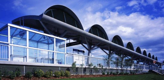
Figure 13.44 Casting of a concrete shell for the Shawnessy LRT Station shown in Figure 13.43. The shells were injection molded, a technique in which the concrete is cast in a fully enclosed mold rather than in a conventional open-sided form. In this photograph, the two halves of a mold have been separated, and the shell is being lifted with the aid of a temporary frame. (Photograph by Tucker Photography. Courtesy of Lafarge North America, Inc.)

Pervious concrete is made with gap- or uniformly graded aggregate so that 15 to 30 percent of the finished concrete consists of open voids. Pervious concrete paving allows rainwater runoff to pass directly through the paving into the soil below, rather than flow across its surface. Pervious paving reduces water volumes directed to municipal stormwater systems and lessens the contamination of nearby bodies of water by surface runoff carrying oils and other contaminants.
Light-transmitting concrete is made from precast concrete blocks or panels with embedded optic fibers or fabrics that allow light to pass through while retaining the strength and durability of the concrete. This recently formulated material is finding application in nonstructural partitions, countertops, and other architectural elements.
Under development is the possibility of self-healing concrete, in which small bacteria- and nutrient-containing granules are added to the concrete mix. When micro-cracks occur and water intrudes into the hardened concrete, the bacteria are activated and produce calcium carbonate (limestone), sealing the crack and protecting the steel reinforcing from corrosion.
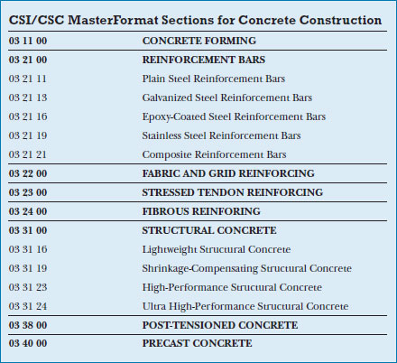
KEY TERMS
REVIEW QUESTIONS
1. What is the difference between cement and concrete?
2. List the conditions that must be met to make a satisfactory concrete mix.
3. List the precautions that should be taken to cure concrete properly. How do these change in very hot, very windy, and very cold weather?
4. What problems are likely to occur if concrete has too low a slump? Too high a slump? How can the slump be increased without increasing the water content of the concrete mixture?
5. Explain how steel reinforcing bars work in concrete.
6. Explain the role of stirrups in beams.
7. Explain the role of ties in columns.
8. What does shrinkage temperature steel do? Where is it used?
9. Explain the differences between reinforcing and prestressing and the relative advantages and disadvantages of each.
10. Under what circumstances would you use pretensioning, and under what circumstances would you use posttensioning?
11. Explain the advantages of using higher-strength reinforcing bars in concrete that requires very heavy reinforcing.
EXERCISES
1. Design a simple concrete mixture. Mix it and pour some test cylinders for several water–cement ratios. Cure and test the cylinders. Plot a graph of concrete strength versus water–cement ratio.
2. Sketch from memory the pattern of reinforcing for a continuous concrete beam. Add notes to explain the function of each feature of the reinforcing.
3. Design, form, reinforce, and cast a small concrete beam, perhaps 6 to 12 feet (2–4 m) long. Get help from a teacher or professional, if necessary, in designing the beam.
4. Visit a construction site where concrete work is being done. Examine the forms, reinforcing, and concrete work. Observe how concrete is brought to the site, transported, placed, compacted, and finished. How is the concrete supported after it has been poured? For how long?
SELECTED REFERENCES
American Concrete Institute. Manual of Standard Practice. Schaumburg, IL, Author, updated regularly.
A compendium of standards for all aspects of reinforced concrete design, mixing, pouring, curing, finishing, and maintenance. Includes ACI 301.
Concrete Reinforcing Steel Institute. Manual of Standard Practice. Schaumburg, IL, Author, updated regularly.
Specifications for reinforcing, steel, welded wire fabric, bar supports, detailing, fabrication, and installation are standardized in this booklet.
Mehta, P. Kumar, and J. M. Monteiro Paulo. Concrete: Microstructure, Properties, and Materials (3rd ed.). New York, McGraw-Hill, 2005.
For the reader who wishes to explore further the science and mechanics of concrete, this text provides an in-depth treatment of concrete materials, formulation, and behavior.
Portland Cement Association. Design and Control of Concrete Mixtures (15th ed.). Skokie, IL, Author, 2011.
The 372 pages of this book summarize clearly and succinctly, with many explanatory photographs and tables, the state of current practice in making, placing, finishing, and curing concrete.
WEB SITES
Concrete Construction
Author's supplementary web site: www.ianosbackfill.com/13_concrete_construction
American Concrete Institute International: www.concrete.org
Concrete Sustainability Hub: web.mit.edu/cshub/
Portland Cement Association: www.cement.org
Reinforcing
Concrete Reinforcing Steel Institute: www.crsi.org