
Kane Hall, University of Washington, 1969. Architects Walker and McGough made bold use of sitecast concrete construction. (Photo by Joseph Iano.)
14
SITECAST CONCRETE FRAMING SYSTEMS
Casting a Concrete Slab on Grade
One-Way Floor and Roof Framing Systems
One-Way Concrete Joist (Ribbed Slab)
Two-Way Floor and Roof Framing Systems
Two-Way Flat Slab and Two-Way Flat Plate
Other Uses of Sitecast Concrete
Sitecast Posttensioned Framing Systems
Selecting a Sitecast Concrete Framing System
Innovations in Sitecast Concrete Construction
Longer Spans in Sitecast Concrete
Designing Economical Sitecast Concrete Buildings
Sitecast Concrete and the Building Codes
Uniqueness of Sitecast Concrete
CASTING A CONCRETE SLAB ON GRADE
A concrete slab on grade is a level surface of concrete that lies directly on the ground. Slabs on grade are used for roads, sidewalks, patios, airport runways, and basements or ground floors of buildings. A slab-on-grade floor usually experiences little structural stress except a direct transmission of compression between its superimposed loads and the ground beneath, so it furnishes a simple example of the operations involved in the sitecasting of concrete (Figure 14.2).
Figure 14.1 Unity Temple in Oak Park, Illinois, was constructed by architect Frank Lloyd Wright in 1906. Its structure and exterior surfaces were cast in concrete, making it one of the earliest buildings in the United States to be built primarily of this material. (Photo by John McCarthy. Courtesy of Chicago Historical Society ICHi-18291.)

Figure 14.2 The construction of a concrete slab on grade. Notice how the welded wire reinforcing is overlapped where two sheets of fabric meet.

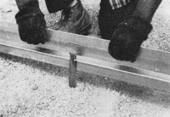
To prepare for the placement of a slab on grade, the unstable topsoil is scraped away to expose the subsoil beneath. If the exposed subsoil is too soft, it is compacted or replaced with more stable material. Next, a layer of 1½-inch-diameter (38-mm) crushed stone at least 4 inches (100 mm) deep, sometimes referred to as a capillary break, is compacted over the subsoil. This acts as a drainage layer to keep moisture away from the underside of the slab. Where the slab is not being cast within surrounding walls, a simple edge form—a strip of wood or metal fastened to stakes driven into the ground—is constructed around the perimeter of the area to be poured and is coated with a form release compound to prevent the concrete from sticking (Figure 14.3a, b). The top edge of the form is carefully leveled; when the slab is poured, this edge will be used to guide the screed that levels the slab surface. Where walls surround the slab to be poured, an isolation joint is creating by inserting a compressible filler material (Figure 14.3c). The thickness of the slab may range from 3 inches (100 mm) for a residential floor to 6 or 8 inches (150 or 200 mm) for an industrial floor. For interior floor slabs on grade, a moisture barrier (also called a vapor retarder), such as a heavy plastic sheet, is laid over the crushed stone to further protect the slab from moisture in the ground (Figure 14.3b).
Figure 14.3 Constructing and finishing a concrete slab on grade. (a) Attaching a slab edge form to a supporting stake. The profile of the edge form causes adjacent pours to interlock. (b) To the right, a crushed-stone drainage layer for a slab on grade, and to the left, a slab section ready to pour, with vapor retarder, welded wire reinforcing, and edge forms in place. (c) Three-quarter-inch-thick asphalt-impregnated fiberboard used to form an isolation joint where slab edges abut walls or other vertical surfaces. The plastic cap is removed immediately after slab finishing to leave a clean slot for the later insertion of an elastomeric joint sealant. (d) Striking off the surface of a concrete slab on grade just after pouring, using a motorized screed. The motor vibrates the screed from end to end to work the wet concrete into a level surface. (e) A bull float is used for initial floating, to flatten and consolidate the slab surface immediately after screeding. (f) Floating, here performed by hand, brings cement paste to the surface and produces a smoother, denser finish. (g) For larger slabs, floating can be done by machine. (h) Steel troweling after floating produces a dense, hard, smooth surface. (i) Damp curing of the slab, here using a polyethylene plastic sheet cover. (j) This slab was cured with a moisture-retaining liquid compound that also provides a protective coating, allowing the next stages of work to proceed sooner on the finished slab. (Photos a, b, c courtesy of Vulcan Metal; d, e, f, g, h reprinted with permission of the Portland Cement Association from Design and Control of Concrete Mixtures, 12th edition; PHOTOS: Portland Cement Association, Skokie, IL; j by Joseph Iano.)
(a)
(b)

(c)

(d)

(e)
(f)

(g)

(h)
(i)

(j)

For some interior floor slab construction, a layer of fine crushed stone or sand, 2 to 4 inches (50 to 100 mm) thick, may be placed over the vapor retarder before concrete is placed; this layer of fine aggregate protects the vapor retarder sheet from damage. As concrete is placed, this layer also absorbs excess water from the concrete. This can help to prevent curling (warping) of the slab that can occur when the top of the slab loses moisture more rapidly than the bottom, a concern especially for some types of industrial floors. However, this practice also runs the risk of creating a reservoir for the storage of water under the slab that can lead to moisture-related problems after the slab is in service. With a better recognition of this risk and the advent of tougher vapor retarder sheets that are less vulnerable to damage, the use of an aggregate layer over the vapor retarder has become less prevalent.
A reinforcing mesh of welded wire reinforcing, cut to a size just a bit smaller than the dimensions of the slab, is laid over the moisture barrier or crushed stone. The reinforcing most commonly used for lightly loaded slabs, such as those in houses, is 6 × 6-W1.4 × W1.4, which has a wire spacing of 6 inches (150 mm) in each direction and a wire diameter of 0.135 inch (3.43 mm). For slabs in factories, warehouses, and airports, a fabric made of heavier wires or a grid of reinforcing bars may be used instead. The grid of wires or bars helps protect the slab against cracking caused by concrete shrinkage during curing, temperature stresses, concentrated loads, frost heaving, or settlement of the ground beneath. Fibrous, macrofiber reinforcing, discussed in Chapter 13, can also be used in addition to or in place of wire reinforcing for the same purposes.
Pouring and Finishing
Casting of the slab commences with the placing of wet concrete in the formwork, using any of the methods described in Chapter 13. The concrete is spread by workers using shovels or rakes until the form is full. Then the same tools, or an immersion vibrator, are used to agitate the concrete slightly, especially around the edges, to eliminate air pockets. Unless the welded wire fabric reinforcing was set on chairs or other supports, the concrete masons reach into the wet concrete with metal hooks and raise this reinforcing to approximately the midheight of the slab. This locates the reinforcing optimally to resist tension caused by forces acting either from above or below the slab.
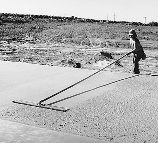
The first operation in finishing the slab is to strike off or screed the concrete by drawing a stiff plank of wood or metal across the top edges of the formwork to achieve a level concrete surface (Figure 14.3d). This is done with an end-to-end sawing motion of the plank that avoids tearing the projecting pieces of coarse aggregate from the surface of the wet concrete. A bulge of concrete is maintained in front of the screed as it progresses across the slab, so that when a low point is encountered, concrete from the bulge will flow in to fill it.
Immediately after striking off the concrete, the slab receives its initial floating. This step is usually performed by hand, using flat-surfaced tools, typically 4 to 10 feet (1.2 to 3 m) in length, called bull floats or darbies (Figure 14.3e). These are drawn across the concrete to flatten and consolidate its surface. After this initial floating, the top of the slab is level but still rather rough. If a concrete topping will later be poured over the slab, or if a floor finish of terrazzo, stone, brick, or quarry tile will be applied, the slab may be left to cure without further finishing.
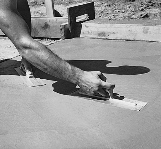
If a smoother surface is desired, additional finishing operations proceed after a period of time during which the concrete begins to stiffen and the watery sheen, called bleed water, evaporates from the surface of the slab. First, specially shaped hand tools may be used to form neatly rounded edges around the perimeter of the slab and control joints in the interior. Next, the slab is floated a second time to further consolidate its surface. At this stage, small slabs may be floated by hand (Figure 14.3f), but for larger slabs, rotary power floats are used (Figure 14.3g). The working surfaces of floats are made of wood or of metal with a slightly rough surface. As the float is drawn across the surface, it gently vibrates the concrete and brings cement paste to the surface, where it is smoothed over the coarse aggregate and into low spots by the float. If too much floating is done, however, an excess of paste and free water rises to the surface and forms puddles, making it almost impossible to get a good finish. Experience on the part of the mason is essential to floating, as it is to all slab finishing operations, to know just when to begin each operation and just when to stop. The floated slab has a lightly textured surface that is appropriate for outdoor walks and pavings without further finishing.
For a completely smooth, dense surface, the slab must also be troweled. This is done immediately after the second floating, either by hand, using a smooth, rectangular steel trowel (Figure 14.3h), or with a rotary power trowel. If the concrete mason cannot reach all areas of the slab from around the edges, squares of plywood called knee boards, two per mason, are placed on the surface of the concrete. These distribute the mason's weight sufficiently that he or she can kneel on the surface without making indentations. Any marks left by the knee boards are removed by the trowel as the mason works backward across the surface from one edge to the other. If a nonslip surface is required, a stiff-bristled janitor's pushbroom may be drawn across the surface of the slab after troweling to produce a striated texture called a broom finish.
Where a concrete slab must meet narrow floor flatness limits, it may be restraightened after each floating or troweling operation. Restraightening is performed with a rectangular flat-bottomed straightedge, roughly 10 feet (3 m) in length, which is drawn across the concrete slab surface to remove minor undulations produced during floating or troweling.
Shake-on hardeners are sometimes sprinkled over the surface of a slab between the screeding and floating operations. These dry powders react with the concrete to form a very hard, durable surface for such heavy-wear applications as warehouses and factories.
When the finishing operations have been completed, the slab should be cured under damp conditions for at least a week; otherwise, its surface may crack or become dusty from premature drying. Damp curing may be accomplished by covering the slab with an absorbent material such as sawdust, earth, sand, straw, or burlap and maintaining the material in a damp condition for the required length of time. An impervious sheet of plastic or waterproof paper may be placed over the slab soon after troweling to prevent the escape of moisture from the concrete (Figure 14.3i). Or, the concrete surface may be sprayed with one or more applications of a liquid curing compound, which forms an almost invisible moisture barrier membrane over the slab surface (Figure 14.3j).
No concrete floor is perfectly flat. The normal finishing process produces a surface that undulates, usually imperceptibly, between low and high areas that go unnoticed in everyday use. Traditionally, the flatness of concrete slabs is specified as the maximum gap size, typically in the range of 1/8 to 3/8 inch (3 to 10 mm), permitted under a 10-foot (3-m) straightedge placed anywhere on the floor. Industrial warehouses that use high-rise forklift trucks, however, require floors whose flatness is controlled to within narrower tolerances. These superflat floors, as well as other floors where close control over flatness is desired, are specified according to a more complicated system of indexes, called F-numbers, that correspond to the degrees of flatness (waviness) and levelness (conformity to a horizontal plane) required, and are produced using special finishing equipment and techniques. Because of its extreme accuracy, a laser-guided automatic straightedging machine (Figure 14.4) is often used in the creation of superflat floors. This device produces a slab surface that is flat and level to within consistently small tolerances, and does so at a very rapid rate.
Figure 14.4 Guided by a laser beam, the motorized straightedging device on this machine can strike off 240 square feet (22 m2) of slab surface per minute to an extremely exacting standard of flatness. The worker to the right smoothes the surface with a bull float. (Photo by Wironen, Inc. Courtesy of the Laser Screed Co., Inc., New Ipswich, NH.)

Controlling Cracking
Because concrete slabs on grade are relatively thin in relation to their horizontal dimensions and normally only lightly reinforced, they are prone to cracking. The stresses that cause cracking may originate from the shrinkage as the concrete cures, thermal expansion and contraction, or differential movement between the slab and abutting building elements. If such cracks are allowed to occur randomly, they can be unsightly and can compromise the functionality of the slab.
The most common method of controlling cracking in concrete slabs on grade is to introduce an organized system of joints into the slab that allow cracking to occur in a neat and visually acceptable pattern. Control joints, also called contraction joints, are intentionally weakened sections created through the concrete slab where the tensile forces caused by concrete drying shrinkage are relieved. They are usually formed as grooves that extend at least one-quarter of the depth of the slab. They are made either by running a special trowel along a straightedge while the concrete is still plastic or by sawing partially through the concrete shortly after it begins to harden using a diamond or abrasive saw blade in a power circular saw. To provide a further inducement for cracks to occur at control joint locations rather than elsewhere, reinforcing in the slab may be partially discontinued where it crosses these joints. Control joint spacing recommendations vary with the thickness of the slab and the shrinkage rate of the concrete. For normal concrete slabs 4 to 8 inches (100–200 mm) thick, joint spacings from 11 feet 6 inches to 17 feet 6 inches (3.6–5.3 m) are recommended, with thinner slabs requiring closer joint spacing than thicker ones. Control joints should be arranged in perpendicular directions such that they create panels roughly square in proportion.
Reinforced concrete made “pilotis” possible. The house is in the air, away from the ground; the garden runs under the house, and it is also above the house, on the roof. . . . Reinforced concrete is the means which makes it possible to build all of one material. . . . Reinforced concrete brings the free plan into the house! Floors no longer have to stand simply one on top of the other. They are free. . . . Reinforced concrete revolutionizes the history of the window. Windows can run from one end of the facade to the other. . . .
—Le Corbusier and P. Jeanneret, Oeuvre Complète 1910–1929, 1956.
Isolation joints, sometimes called expansion joints, are formed by casting full-depth preformed joint materials, typically 3/8 to ¾ inch (10–20 mm) in width, into the slab (Figure 14.3c), completely separating the slab from adjacent elements. Isolation joints allow freedom of movement of the slab with respect to other building parts or other portions of the slab—movements that may occur due to thermal expansion and contraction, structural loading, or differential settlement. Isolation joints are commonly provided where the edge of a concrete slab abuts walls or curbs, as well as around columns or loadbearing walls that pass through the slab within its perimeter. Isolation joints are also used to divide large or irregularly shaped slabs into smaller, more simply shaped areas that are less prone to stress accumulation.
Concrete itself can be manipulated to reduce cracking: Shrinkage-reducing chemical admixtures and some supplementary cementitious materials, such as fly ash, reduce drying shrinkage. Lowering the water–cement ratio of the concrete mix reduces drying shrinkage and results in finished concrete that is stronger and more crack resistant, though at increased cost. Specially formulated shrinkage-compensating cements can completely nullify drying shrinkage, allowing the casting of large slabs on grade that are entirely free of contraction joints. The amount of reinforcing in the slab can be increased or fibrous reinforcing can be added to the concrete mix to enhance the slab's resistance to tensile forces. Protecting a freshly poured concrete slab from premature drying during the damp curing process reduces cracking while the concrete hardens and ensures that the concrete attains its full design strength.
A slab on grade may also be posttensioned, using level tendons in both directions at the midheight of the slab in place of conventional reinforcing. Posttensioning places the entire slab under sufficient compression to have it remain free from tensile stress under any anticipated loading condition. Posttensioning eliminates the need for control joints, makes floors more resistant to concentrated loads, and often permits the use of a thinner slab. It is especially effective for slabs over unstable or inconsistent soils and for superflat floors.
CASTING A CONCRETE WALL
A reinforced concrete wall at ground level usually rests on a poured concrete strip footing (Figures 14.5, 14.6, and 14.7). The footing is formed and poured much like a concrete slab on grade. Its cross-sectional dimensions and its reinforcing, if any, are determined by the structural engineer. A key, a groove that will form a mechanical connection to the wall, is sometimes formed in the top of the footing with strips of wood that are temporarily embedded in the wet concrete. In addition, vertical dowels consisting of steel reinforcing bars are usually installed in the footing; these will later be overlapped with the bars in the walls to form a structural connection. After pouring, the top of the footing is screeded; no further finishing operations are required. The footing is left to cure for at least a day before the wall forms are erected.
Figure 14.5 The process of casting a concrete wall. (a) Vertical reinforcing bars are wired to the dowels that project from the footing, and horizontal bars are wired to the vertical bars. (b) The formwork is erected. Sheets of plywood form the faces of the concrete. They are supported by vertical wood studs. The studs are supported against the pressure of the wet concrete by horizontal walers. The walers are supported by steel rod ties that pass through holes in the plywood to the walers on the other side. The ties also act as spreaders to maintain a spacing between the plywood walls that is equal to the desired thickness of the wall. Diagonal braces keep the whole assembly plumb and straight. (c) After the concrete has been poured, consolidated, and cured, the wedges that secure the walers to the form ties are driven out, the formwork is pulled off the concrete, and the projecting ends of the form ties are broken off.


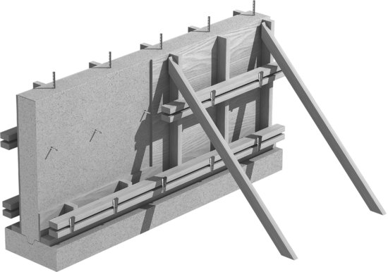
Figure 14.6 Protected against falling by a safety harness, a worker stands on the reinforcing bars for a concrete wall to wire another horizontal bar in position. (Photo courtesy of DBI/SALA, Red Wing, MN.)

Figure 14.7 Section through a reinforced concrete wall, with two layers of horizontal and vertical reinforcing bars for greater strength.

The wall reinforcing, either in one vertical layer of horizontal and vertical bars at the center of the wall or two layers near the faces of the wall, as specified by the structural engineer, is installed next, with the bars wired to one another at the intersections. The vertical bars are overlapped with the dowels projecting from the footing. L-shaped horizontal bars are installed at wall corners to maintain structural continuity between the two portions of the wall. If the top of the wall will connect to a concrete floor or another wall above, rods are left projecting from the formwork. These will be embedded in the later pour of concrete to form a continuous connection.
Wall forms may be custom-built of lumber and plywood for each job, but it is more usual to employ reusable prefabricated panels. The panels for one side of the form are coated with a form release compound, set on the footing, aligned, and braced. The form ties, which are small-diameter steel rods specially shaped to hold the formwork together under the pressure of the wet concrete, are inserted through holes provided in the formwork panels and secured to the back of the form by devices supplied with the ties. Both ties and fasteners vary in detail from one manufacturer to another and the type of wall being constructed. A typical example is shown in Figure 14.8. The ties will pass straight through the concrete wall from one side to the other, with all but the ends remaining embedded permanently in the wall after it is poured.
Figure 14.8 Detail of a typical form tie assembly. Plastic cones just inside the faces of the form hold the faces in position. Special hardware at the tie ends clamps against the walers. After the forms have been stripped, the cones will be removed from the concrete and the ties snapped off inside the voids left by the cones. The conical holes may be left open, filled with mortar, or plugged with conical plastic plugs. (Photographs courtesy of Richmond Screw Anchor Co., Inc., 7214 Burns Street, Fort Worth, TX 76118.)
When the ties are in place and the reinforcing has been inspected, the formwork for the second side of the wall is erected, the walers and braces are added, and the forms are inspected to be sure that they are straight, plumb, correctly aligned, and adequately tied and braced. A surveyor's transit or laser leveling device is used to establish the exact height to which the concrete will be poured, and this height is marked all around the inside of the forms (Figures 14.9 and 14.10). Pouring may then proceed.
Figure 14.9 Wall formwork, similar to that diagrammed in Figure 14.5, has been erected and bracing is being added. In the background the wall reinforcing is still exposed. Bent reinforcing bars projecting from the top of the formwork will connect to a concrete slab yet to be poured. In the background, bars project vertically, for added wall construction to continue above. (Photo by Joseph Iano.)
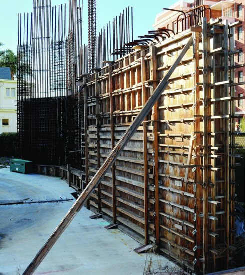
Figure 14.10 Heavy-strength wall formwork for a 40-ft (12-m)-plus-tall concrete wall. (Photo by Joseph Iano.)

Concrete is brought to the site, test cylinders are made, and a slump test is performed to check for the proper pouring consistency. Workers standing on planks at the tops of the forms deposit the concrete into the forms, consolidating it with a vibrator to eliminate air pockets (Figure 14.11). When the form has been filled and consolidated up to the level that was marked inside the formwork, hand floats are used to smooth and level the top of the wall. The top of the form is then covered with a plastic sheet or canvas, and the wall is left to cure.
Figure 14.11 Consolidating wet concrete after pouring, using a mechanical vibrator immersed in the concrete. (Reprinted with permission of the Portland Cement Association from Design and Control of Concrete Mixtures, 12th edition; Photos: Portland Cement Association, Skokie, IL.)

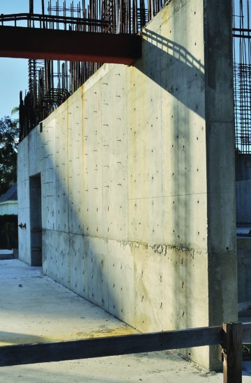
After a few days of curing, the bracing and walers are taken down, the connectors are removed from the ends of the form ties, and the formwork is stripped from the wall (Figure 14.12). This leaves the wall bristling with projecting form tie ends. These are twisted off with heavy pliers, and the form tie holes that they leave in the surfaces of the wall are carefully filled with grout. If required, major defects in the wall surface, such as caused by poor consolidation of the concrete, can be repaired at this time. The wall is now complete.
Figure 14.12 A concrete wall with formwork stripped. In the foreground and along the bottom of the wall, the form tie ends have been snapped off. Elsewhere, they still protrude from the wall. (Photo by Joseph Iano.)
Insulating Concrete Forms
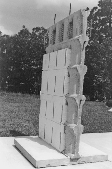
Insulating concrete forms (ICFs) serve to contain the concrete when the wall is poured but, unlike conventional formwork, also become a permanent part of the wall, for which they act as thermal insulation (Figure 14.13). The forms are manufactured in differing configurations. Most are some kind of interlocking hollow blocks of polystyrene foam. Other manufacturers produce planks or panels of foam with plastic ties that join them to make wall forms. Whatever the configuration, these systems weigh so little and are so accurately made that they can be assembled almost as easily and quickly as a child's plastic building blocks. The tops of the blocks are channeled in such a way that horizontal reinforcing bars may be laid in the top of each course and vertical bars may be inserted into the vertical cores. The wall forms must be braced to prevent them from moving during the concrete pour. Concrete is usually deposited in the cores of the foam blocks from the hose of a pump. The full height of a wall cannot be cast in one operation because the pressure of so great a depth of wet concrete would blow out the sides of the fragile blocks. The normal procedure is to deposit the concrete in several lifts of limited height, working all the way around the structure with each lift so that by the time the second lift is begun, the first lift has had an hour or two to harden somewhat, relieving the pressure at the bottom of the forms. Interior and exterior finish materials must be applied to the foam plastic faces to protect them from sunlight, mechanical damage, and fire. The thermal insulating value of the finished wall is usually in the range of R-17 to R-22 (RSI-3.0 to RSI-3.9).
Figure 14.13 Insulating concrete forms are manufactured as interlocking blocks or panels. In the system illustrated here, the inner and outer halves of the blocks are tied together by steel mesh webs that connect to sheet metal strips on the outer surfaces. These strips later serve to receive screws that fasten interior and exterior finish materials to the wall. (a) Workers stack the blocks to form the exterior walls of a house. Openings for doors and windows are formed with dimension lumber. Blocks can be cut to length with a simple hand saw. (b) This sample wall, from which some of the blocks have been removed, shows that the completed wall contains a continuous core of reinforced concrete with thermal insulation inside and out. (Courtesy: American Polysteel Forms.)
(a)

(b)
CASTING A CONCRETE COLUMN
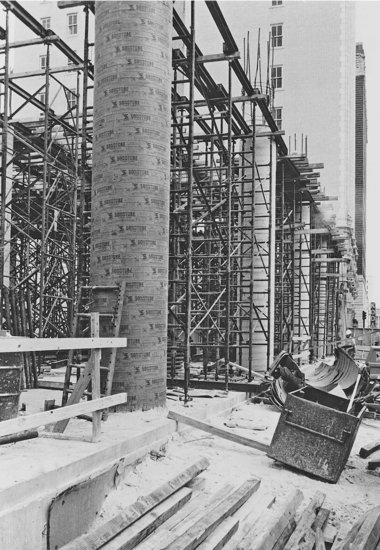
A column is formed and cast much like a wall, with a few important differences. The footing is usually an isolated column footing, a pile cap, or a caisson rather than a strip footing (Figure 14.14). The dowels are sized and spaced in the footing to match the vertical bars in the column. The cage of column reinforcing is assembled with wire ties and hoisted into place over the dowels. If space is too tight in the region where the vertical bars and dowels overlap, the bars may be spliced end to end with welds or mechanical connectors instead (Figure 13.24). The column form may be a rectangular box of plywood or composite panels, a cylindrical steel or plastic tube bolted together in halves so that it can later be removed, or a waxed cardboard tube that is stripped after curing by unwinding the layers of paper that make up the tube (Figures 14.15, 14.16, and 14.54). Unless a rectangular column is very broad and wall-like, form ties through the concrete are not required. The vertical bars project from the top of the column to overlap or splice to the bars in the column for the story above, or they are bent over at right angles to splice into the roof structure. Where vertical bars overlap, the tops of the bars from the column below are offset (bent inward) by one bar diameter to avoid interference.
Figure 14.14 (a) A column footing almost ready for pouring but lacking dowels. The reinforcing bars are supported on pieces of concrete brick. (b) Column footings poured with projecting dowels to connect to both round and rectangular columns. (Photos by Edward Allen.)
(a)

(b)

Figure 14.15 In the foreground, a square column form is tied with pairs of L-shaped steel brackets. In the background, a worker braces a round column form made of sheet steel. (Courtesy of the Ceco Corporation, Oakbrook Terrace, IL.)

Figure 14.16 Round columns may also be formed with single-use heavy cardboard tubes. Notice the density of the steel shoring structure that is being erected to support the slab form, which will carry a very heavy load of wet concrete. (Courtesy of Sonoco Products Company.)
ONE-WAY FLOOR AND ROOF FRAMING SYSTEMS
One-Way Solid Slab
A one-way solid slab (Figures 14.17, 14.18, and 14.19) spans across lines of support furnished by walls or beams. The walls and columns are poured before the formwork for the slab is erected, but the forms for the girders and beams are nearly always built continuously with those for the slab, and girders, beams, and slab are poured simultaneously as a single piece.
Figure 14.17 Plan and larger-scale section of a typical one-way solid slab system. For the sake of clarity, the girder and beam reinforcing are not shown in the plan, and the girder and column reinforcing are left out of the section. The slabs span between the beams, the beams are supported by the girders, and the girders rest on the columns. You can download a PDF of this figure at http://www.wiley.com/go/aflblce6ne.

Figure 14.18 Isometric view of a one-way solid slab system under construction. The slab, beams, and girders are created in a single pour. You can download a PDF of this figure at http://www.wiley.com/go/aflblce6ne.

Figure 14.19 An example of a beam–column connection in a one-way solid slab structure, with the slab reinforcing omitted for clarity. Notice how the column bars are spliced by overlapping them just above floor level. The bars from the column below are offset at the top so that they lie just inside the bars of the column above at the splice. Structural continuity between the beam and column is established by running the top bars from the beam into the column. U-stirrups are shown in the beam; closed stirrup ties, shown in the inset detail, are often used instead.

The girder and beam forms are erected first, then the slab forms. The forms are supported on temporary joists and beams of metal or wood, and the temporary beams are supported on temporary shores (adjustable-length columns). The weight of uncured concrete that must be supported is enormous, and the temporary beams and shoring must be both strong and closely spaced. Formwork is, in fact, designed by a contractor's structural engineers as carefully as it would be if it were a permanent building, because a structural failure in formwork is an intolerable risk to workers and property.
Edges of concrete structural elements are beveled or rounded by inserting shaped strips of wood or plastic into the corners of the formwork to produce the desired profile. This is done because sharp edges of concrete often break off during form stripping to leave a ragged edge that is almost impossible to patch. In service, sharp edges are easily damaged by, and are potentially damaging to, people, furniture, and vehicles.
A form release compound is applied to all formwork surfaces that will be in contact with concrete. Then, in accordance with reinforcing diagrams and schedules prepared by the structural engineer, the girder and beam reinforcing—bottom bars, top bars, and stirrups—is installed in the forms, supported on chairs and bolsters to maintain the required cover of concrete. Next, the slab reinforcing—bottom bars, top bars, and shrinkage–temperature bars—is placed on bolsters. After the reinforcing and formwork have been inspected, the girders, beams, and slab are poured in a single operation, with sample cylinders being made for later testing to be sure that the concrete meets its specified strength. One-way slab depths are typically 4 to 10 inches (100–250 mm), depending on the span and loading intensity. The top of the slab is finished in the same manner as a slab on grade, usually to a steel trowel finish, and the slab is sealed or covered for damp curing. The only components left projecting above the slab surface at this stage are the offset column bars, which are now ready to overlap with, or splice to, the column bars for the floor above.
When the slab and beams have attained enough strength to support themselves safely, the formwork is stripped and the slabs and beams are reshored with vertical props to relieve them of loads until they have reached full strength, which will take several more weeks. Meanwhile, the formwork and the remainder of the shoring are cleaned and moved up a level above the slab and beams just poured, where the cycle of forming, reinforcing, pouring, and stripping is repeated (Figure 14.20).
Figure 14.20 Reshoring supports the first slab above grade, which was recently stripped. Above that, formwork for the next level concrete slab has been installed. The columnar supports for reshoring and formwork look similar. But reshoring is installed after the slab formwork has been removed and each column makes direct contact with the underside of the concrete above. The supports for formwork contact the underside of the formwork. (Photo by Joseph Iano.)
Ordinarily, the most efficient and economical concrete beam is one whose depth is twice or three times its breadth. One-way solid slabs are often supported, however, by beams that are several times as broad as they are deep. These are called slab bands (Figure 14.21). Banded slab construction offers two kinds of economy: The width of the slab band reduces the span between the bands, which can result in a reduced thickness for the slab and consequent savings of concrete and reinforcing steel. Also, the reduced depth of the slab band compared to a more conventionally proportioned beam allows reduction of the story height of the building, with attendant economies in columns, cladding, partitions, and vertical runs of piping and ductwork.
Figure 14.21 Banded slab construction. Compare the depth and breadth of the slab band in the center of the building to those of the conventional concrete beams around the perimeter. (Reprinted with permission of the Portland Cement Association from Design and Control of Concrete Mixtures, 12th edition; Photos: Portland Cement Association, Skokie, IL.)

Figure 14.22 This helical ramp is a special application of one-way solid slab construction. The formwork is made of overlaid plywood for a smooth surface finish. (Courtesy American Plywood Association.)
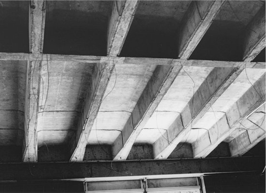
One-Way Concrete Joist (Ribbed Slab)
As one-way solid slab spans increase, a progressively thicker slab is required. Beyond a certain span, the slab becomes so thick that its own weight becomes an excessive burden, unless a substantial portion of the nonworking concrete in the lower part of the slab can be eliminated to lighten the load. This is the rationale for the one-way concrete joist system (Figures 14.23 through 14.26), also called a ribbed slab. The bottom steel is concentrated in spaced ribs or joists. The thin slab that spans across the top of the joists is reinforced only by shrinkage-temperature bars. There is little concrete in this system that is not working, with the result that a one-way concrete joist system can efficiently and economically span considerably longer distances than a one-way solid slab. Each joist is reinforced as a small beam, except that stirrups are not usually used, because of the restricted space in the narrow joist. Instead, the ends of the joists are broadened sufficiently that the concrete itself can resist the diagonal tension forces.
Figure 14.23 Plan and larger-scale section of a typical one-way concrete joist system. For the sake of clarity, no reinforcing is shown in the plan, and the column reinforcing is not shown on the section. All bottom and top reinforcing occurs in the ribs, and all shrinkage–temperature bars are placed in the slab.

Figure 14.23 (Continued)

Figure 14.24 Standard steel form dimensions for one-way concrete joist construction. (One inch equals 25.4 mm.) (Courtesy of the Ceco Corporation, Oakbrook Terrace, IL.)

Figure 14.25 Reinforcing being placed for a one-way concrete joist floor. Electrical conduits and boxes have been put in place, and welded wire fabric is being installed as shrinkage–temperature reinforcing. Both the tapered end pans and the square endcaps for the midspan distribution rib are clearly visible. (Courtesy of the Ceco Corporation, Oakbrook Terrace, IL.)

Figure 14.26 A one-way concrete joist system after stripping of the formwork, showing broadened joist ends at the lower edge of the photograph and a distribution rib in the foreground. The dangling wires are hangers for a suspended finish ceiling. (Reprinted with permission of the Portland Cement Association from Design and Control of Concrete Mixtures, 12th edition; Photos: Portland Cement Association, Skokie, IL.)
The joists are formed with metal or plastic pans supported on a temporary plywood deck. Pans are available in two standard widths, 20 inches (508 mm) and 30 inches (762 mm), and in depths ranging up to 20 inches (508 mm), as shown in Figure 14.24. The sides of the pans taper from bottom to top, to allow them to drop easily from the hardened concrete. The joist width can be varied by placing the rows of pans closer together or farther apart. The bottom of each joist is formed by the wood deck on which the pans are placed. The joist ends are broadened with standard end pans whose width tapers. A distribution rib is sometimes formed across the joists at midspan to distribute concentrated loads to more than one joist. After application of a form release compound, the beam and joist reinforcing are placed, the shrinkage–temperature bars are laid crosswise on bolsters over the pans, and the entire system is poured and finished (Figures 14.25 and 14.26).
One-way concrete joists are usually supported on joist bands, which are broad beams that are only as deep as the joists. Although a deeper beam would be more efficient structurally, a joist band is formed by the same plywood deck that supports the pans, which eliminates expensive beam formwork entirely and produces a simpler underside of slab profile with a uniform floor-to-ceiling height throughout.
Wide-Module Concrete Joist
When fire-resistance requirements of the building code dictate a slab thickness of 4½ inches (115 mm) or more, the slab is capable of spanning a much greater distance than the normal space between joists in a one-way concrete joist system. This has led to the development of the wide-module concrete joist system, also called the skip-joist system, in which the joists are placed 4 to 6 feet (1220–1830 mm) apart. The name “skip-joist” arose from the original practice of achieving this wider spacing by laying strips of wood over alternate joist cavities in conventional joist pan formwork to block out the concrete. Pans are now specially produced for wide-module construction (Figures 14.27 and 14.28).
Figure 14.27 Formwork for a wide-module concrete joist system. These pans have been placed over a flat plywood deck, which will also serve to form the bottoms of the joist band beams. (Courtesy of the Ceco Corporation, Oakbrook Terrace, IL.)

Figure 14.28 The underside of the finished wide-module joists, joist bands, and slab. (Courtesy of the Ceco Corporation, Oakbrook Terrace, IL.)

Because wide-module joists must each carry about double the weight carried by conventionally spaced joists, stirrups are required near the ends of each joist. If conventional U-stirrups are used, they must be installed on a diagonal as seen from above, in order to fit into the narrow joist, or single-leg stirrups may be used instead.
TWO-WAY FLOOR AND ROOF FRAMING SYSTEMS
Two-Way Flat Slab and Two-Way Flat Plate
Where columns supporting a slab can be arranged in bays that are square or nearly square in proportion, two-way concrete framing systems that are more economical than one-way systems can be used. A two-way solid slab system is rarely seen, though it is occasionally used for very heavily loaded industrial floors; in such a system, the slab is supported by a grid of beams running in both directions over the columns. Most two-way floor and roof framing systems, however, even for heavy loadings, are made without beams. The slab is reinforced in such a way that the varying stresses in the different zones of the slab are accommodated within a uniform thickness of concrete. This simplifies formwork construction and reinforcing bar patterns considerably.
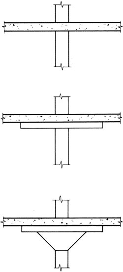
The two-way flat slab (Figure 14.29), a system suited to heavily loaded buildings such as storage and industrial buildings, illustrates this concept. The formwork is completely flat except for a thickening of the concrete to resist the high shear forces around the top of each column. Traditionally, this thickening was accomplished with both a funnel-shaped mushroom capital and a square drop panel, but today the capital is usually eliminated to reduce the formwork cost, leaving a drop panel to do the work alone (Figure 14.30). Typical depths for the slab itself range from 6 to 12 inches (150 to 300 mm).
Figure 14.29 Plan and larger-scale section of a typical two-way flat slab system. The reinforcing pattern consists of column strips and middle strips, with each strip changing pattern slightly around the perimeter of the building to accommodate the different bending forces that occur in the edge panels. The system shown uses only drop panels without mushroom capitals. The reinforcing in a two-way flat plate system is essentially identical to this example; the only difference is that the flat plate has no drop panels.

Figure 14.29 (Continued)
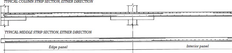
Figure 14.30 Column capitals for two-way concrete framing systems. For slabs bearing heavy loads, shear stresses around the column are reduced by means of a mushroom capital and drop panel or a drop panel alone. For lighter loads, no thickening of the slab is required.
Reinforcing for a two-way slab is laid in both directions in half-bay-wide strips of two fundamental types: Column strips are designed to carry the higher bending forces encountered in the zones of the slab that cross the columns. Middle strips have a lighter reinforcing pattern. Shrinkage–temperature steel is not needed in two-way systems because the concrete is already reinforced in both directions to resist bending. The drop panel and capital (if any) have no additional reinforcing beyond that provided by the column strip; the greater thickness of concrete furnishes the required shear resistance.
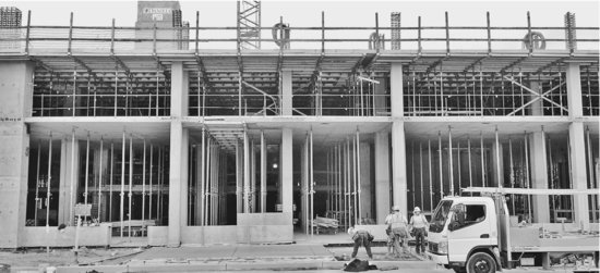
In more lightly loaded buildings, such as hotels, hospitals, dormitories, and apartment buildings, the slab need not be thickened at all over the columns. This makes the formwork extremely simple and even allows some columns to be moved off the grid somewhat if it will improve the arrangement of the floor plan. The completely flat ceilings of this system allow room partitions to be placed anywhere with equal ease. Because there are no beams or girders, only a thin slab, the story heights of the building may be kept to an absolute minimum, which reduces the costs of exterior cladding and other systems. Typical slab depths for such a two-way flat plate system range from 5 to 12 inches (125–305 mm) (Figure 14.31).
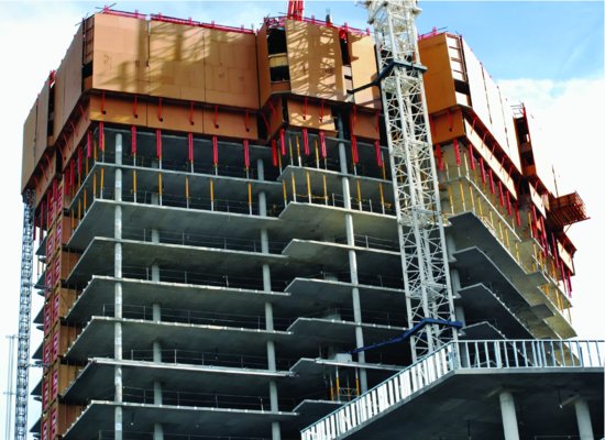
Figure 14.31 Flat plate construction for a high-rise apartment building. Columns located off of a regular grid are readily accommodated by this system. Note the cantilevered slab edges, very thin floor slabs, and minimal floor-to-floor heights. Reshoring is in place on two of the upper floors. A climbing system of formwork and protection from the weather tops out the structure.
The zones along the exterior edges of both the two-way flat slab system and the two-way flat plate system require special attention. To take full advantage of structural continuity, the slabs should be cantilevered beyond the last row of columns a distance equal to about 30 percent of the interior span. If such a cantilever is impossible, additional reinforcing must be added to the slab edges to carry the higher stresses that will result.
Because a two-way flat plate has no drop panel, it requires additional reinforcing in the slab at the top of each column to resist the high shear stresses that occur in this region. This can be accomplished with added conventional steel reinforcing bars or a more compact, proprietary system of shear studs (Figure 14.32).
Figure 14.32 The high shear forces around the top of the column require either added conventional reinforcing or a system such as the Studrails shown here. The remainder of the slab reinforcing has not yet been installed. (U.S. and Canada patents Nos. 4406103 and 1085642, respectively. Licensee: Deha, represented by Decon, 105C Atsion Rd., P.O. Box 1575, Medford, NJ 08055-6675 and 35 Devon Road, Bramton, Ontario L6T 5B6. US: 1-800-527-7245.)

Two-Way Waffle Slab
The waffle slab, or two-way concrete joist system (Figure 14.33), is the two-way equivalent of the one-way concrete joist system. Metal or plastic pans called domes are used as formwork to eliminate nonworking concrete from the slab, allowing considerably longer spans than are feasible with the two-way flat plate. The standard domes form joists on 36-inch (914-mm), 48-inch (1219-mm), and 60-inch (1524-mm) centers, in a variety of depths up to 24 inches (610 mm) (Figures 14.34 and 14.35). Solid concrete heads are created around the tops of the columns by leaving the domes out of the formwork in these areas. A head serves the same function as a drop panel in the two-way flat slab system. If a waffle slab cannot be cantilevered at the perimeter of the building, a solid perimeter beam must also be provided. The waffle slab system is suited to longer-span, heavily loaded applications, and its coffered underside presents rich architectural opportunities as an exposed ceiling (Figure 14.36). However, the complexity of waffle slab formwork also makes it the most expensive of sitecast framing systems.
Figure 14.33 Plan and larger-scale section of a typical two-way concrete joist system, also known as a waffle slab. For the sake of clarity, no reinforcing is shown on the plan drawing, and the section does not show the welded wire fabric that is spread over the entire form before pouring.

Figure 14.33 (Continued)

Figure 14.34 Some examples of steel dome forms for two-way concrete joist construction. (One inch equals 25.4 mm.) (Courtesy of the Ceco Corporation.)

Figure 14.35 Steel domes being placed on a temporary plywood deck to form a two-way concrete joist floor. Pans are omitted around columns to form solid concrete heads. (Courtesy of the Ceco Corporation.)

Figure 14.36 The underside of a two-way concrete joist floor. Notice how the joists are cantilevered beyond the column line for maximum structural efficiency. (Courtesy of the Ceco Corporation.)

OTHER USES OF SITECAST CONCRETE
Sitecast concrete finds a variety of other uses in the construction of most buildings, such as site pavings and curbs, raised pads for mechanical equipment, toppings over metal or precast concrete decking, stairs, and other uses.
Concrete is frequently used to fill the pans of a metal stair. Also, stairs may be constructed wholly of concrete, as illustrated in Figure 14.37. A concrete stair may be thought of as an inclined one-way solid slab. The underside of the formwork is planar. The top is built with riser forms, which are usually inclined to provide greater toe space and make the stair more comfortable to users. The concrete is poured in one operation, and the treads are tooled to a steel trowel finish.
Figure 14.37 Section through a simple sitecast concrete stair.

SITECAST POSTTENSIONED FRAMING SYSTEMS
Posttensioning can be applied to any of the sitecast concrete framing systems. It is used in beams, girders, and slabs, both one-way and two-way, to reduce member sizes, reduce deflection, and extend spanning capability.
Two-way flat plate structures are very commonly posttensioned, especially when spans are long or restrictions on the height of the building require minimal slab depths. The tendon layout, however, is quite different from the conventional reinforcing layout shown in Figure 14.29. Instead of being placed identically in both directions, the draped tendons are evenly distributed in one direction and banded closely together over the line of columns in the other direction (Figures 14.38 and 14.39). This arrangement functions better structurally in posttensioned slabs because it balances the maximum upward force from the banded tendons against the maximum downward force from the distributed tendons. It is also much easier to install than distributed, draped tendons running in both directions. If the structural bay is square, the same number of tendons is used in each direction. The prestressing force from the banded tendons becomes evenly distributed throughout the width of the slab within a short distance of the end anchorages because of action of the concrete.
Figure 14.38 A plan and two larger-scale sections of the tendon layout in a two-way flat plate floor with banded posttensioning. The number of tendons running in each of the two directions is identical, but those in one direction are concentrated into bands that run over the tops of the columns. The draping of the tendons is evident in the two section drawings. Building codes require that at least two distributed tendons run directly over each column to help reinforce against shear failure of the slab in this region. In addition to the tendons, conventional steel reinforcing is used around the columns and in midspan, but this has been omitted from these drawings for the sake of clarity.

Figure 14.38 (Continued)

Figure 14.39 Banded tendons run directly through the concrete column of this flat plate floor. A substantial amount of conventional reinforcing is used here for shear reinforcing. Notice the end anchorage plates nailed to the vertical surface of the formwork at the upper right; see also Figure 13.39. (Courtesy of Post-Tensioning Institute.)

As with any prestressed concrete framing system, both short-term and long-term losses of prestressing force must be anticipated. The short-term losses in posttensioning are caused by elastic shortening of the concrete, friction between the tendons and the concrete, and initial movements (set) in the anchorages. The long-term losses are caused by concrete shrinkage, concrete creep, and steel relaxation. The structural engineer calculates the total of these expected losses and specifies an additional amount of initial posttensioning force to compensate for them.
SELECTING A SITECAST CONCRETE FRAMING SYSTEM
Preliminary factors to be considered in the selection of a sitecast concrete framing system for a building include the following (Figures 14.40 and 14.41):
Figure 14.40 The one-way sitecast concrete framing systems. (a) One-way solid slab with beams and girders. (b) One-way solid slab with slab bands. (c) One-way concrete joist system (rib slab) with joist bands. (d) Wide-module joist system with joist bands. (Illustrations by Edward Allen.)
(a)

(b)

(c)

(d)
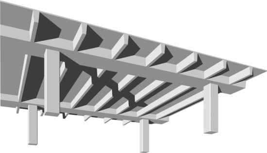
Figure 14.41 The two-way sitecast concrete framing systems. (a) Two-way solid slab. (b) Two-way flat slab with drop panels and mushroom capitals. (c) Two-way flat plate. (d) Two-way concrete joist system (waffle slab). (Drawings by Edward Allen.)
(a)

(b)

(c)

(d)

INNOVATIONS IN SITECAST CONCRETE CONSTRUCTION
The development of sitecast concrete construction continues along several lines. The basic materials, concrete and steel, continue to undergo innovations, as described in Chapter 13. The continuing evolution of high-strength, high-stiffness concrete, along with improvements in concrete forming systems and concrete pumping technology, have enabled sitecast concrete construction to remain economically competitive with structural steel for buildings of virtually any type or size. One of the world's tallest buildings, the Burj Khalifa in Dubai, United Arab Emirates, is constructed for most of its height as a steel-reinforced sitecast concrete structure. Self-consolidating concrete with strengths as high as 14,500 psi (100 MPa) was used in its construction.
Formwork generally accounts for more than half the cost of conventional sitecast concrete construction. Efforts to reduce this cost have led to many innovations, including new types of formwork panels that are especially smooth, durable, and easy to clean after they have been stripped. These can be reused dozens of times before they wear out.
- Estimate the depth of a one-way solid slab at 1/12 of its span if it is conventionally reinforced or 1/10 of its span if it is posttensioned. Depths range typically from 4 to 10 inches (100–250 mm).
- Estimate the total depth of a one-way concrete joist system or wide-module system at 1/18 of its span if it is conventionally reinforced or 1/36 of its span if it is posttensioned. To arrive at the total depth, a slab thickness of 3 to 4½ inches (75–115 mm) must be added to the depth of the pan that is selected.
- Estimate the depth of concrete beams at 1/16 of their span if they are conventionally reinforced or 1/24 of their span if they are posttensioned. For concrete girders, use ratios of 1/12 and 1/20, respectively.
- Estimate the depth of two-way flat plates and flat slabs at 1/30 of their span if they are conventionally reinforced or 1/45 of their span if they are posttensioned. Typical depths are 5 to 12 inches (125–305 mm). The minimum column size for a flat plate is approximately twice the depth of the slab. The width of a drop panel for a flat slab is usually one-third of the span, and the projection of the drop panel below the slab is about one-half the thickness of the slab.
- Estimate the depth of a waffle slab at 1/24 of its span if it is conventionally reinforced or 1/35 of its span if it is posttensioned. To arrive at the total depth, a slab thickness of 3 to 4½ inches (75–115 mm) must be added to the depth of the dome that is selected.
- To estimate the size of a concrete column of normal height, add up the total roof and floor area supported by the column. A 12-inch (300-mm) column can support up to about 2000 square feet (190 m2) of area, a 16-inch (400-mm) column 4000 square feet (370 m2), a 20-inch (500-mm) column 6000 square feet (560 m2), a 24-inch (600-mm) column 9000 square feet (840 m2), and a 28-inch (700-mm) column 10,500 square feet (980 m2). These sizes are greatly influenced by the strength of the concrete used and the ratio of reinforcing steel to concrete. Columns are usually round or square.
- To estimate the thickness of a concrete loadbearing wall, add up the total width of floor and roof slabs that contribute load to the wall. An 8-inch (200-mm) wall can support approximately 1200 feet (370 m) of slab, a 10-inch (250-mm) wall 1500 feet (460 m), a 12-inch (300-mm) wall 1700 feet (520 m), and a 16-inch (400-mm) wall 2200 feet (670 m). These thicknesses are greatly influenced by the strength of the concrete used and the ratio of reinforcing steel to concrete.
Lift-slab construction, used chiefly with two-way flat plate structures, virtually eliminates formwork. The floor and roof slabs of a building are cast in a stack on the ground. Then hydraulic jacks are used to lift the slabs up the columns to their final elevations, where they are welded in place using special cast-in-place steel slab collars (Figure 14.42).
Figure 14.42 Lift-slab construction in progress. The paired steel rods silhouetted against the sky to the right are part of the lifting jacks seen at the tops of the columns. In North America, this form of construction is used infrequently, in part due to a history of past construction accidents. (Reprinted with permission of the Portland Cement Association from Design and Control of Concrete Mixtures, 12th edition; Photos: Portland Cement Association, Skokie, IL.)

Ganged forms for wall construction are large units made up of a number of panels that are supported by the same set of walers. These are handled by cranes and are often more economical than conventional small panels that are maneuvered by hand. For floor slabs that are cast in place, flying formwork is fabricated in large sections that are supported on deep metal trusses. The sections are moved from one floor to the next by crane, eliminating much of the labor usually expended on stripping and reerecting formwork (Figure 14.43).
Figure 14.43 Flying formwork for a one-way concrete joist system being moved from one floor to the next in preparation for pouring. Stiff metal trusses allow a large area of formwork to be handled by a crane as a single piece. (Courtesy of Molded Fiber Glass (MFG) Concrete Forms Company.)

Slip forming is used for tall-walled structures such as elevator shafts, stairwells, and storage silos. A ring of formwork is pulled steadily upward by jacks supported on the vertical reinforcing bars or previously cast sections of the concrete, while workers add concrete and horizontal reinforcing in a continuous process. Manufacturers of concrete formwork have developed more sophisticated systems of self-climbing formwork that offer many advantages over conventional slip forming (Figure 14.44).
Figure 14.44 A proprietary system of self-climbing formwork is being used to form these sitecast concrete elevator shafts for a tall building. The top level is a working surface from which reinforcing bars are handled and the concrete is poured. The outer panels of the formwork are mounted on overhead tracks just beneath the top level. The panels can be rolled back to the outside of the perimeter walkway after each pour, allowing workers to clean the formwork and install the reinforcing for the next pour. The entire two-story apparatus raises itself a story at a time with built-in hydraulic jacks. (Courtesy of Patent Scaffolding Company, Fort Lee, NJ.)

In tilt-up construction, reinforced concrete wall panels are cast lying down over a previously poured slab that serves as a level, smooth work surface. When the wall panels have cured to sufficient strength, they are tilted up into a vertical orientation and hoisted into position by a crane, then grouted together. The elimination of most of the usual wall formwork results in formwork costs that are typically less than 5 percent of the cost of the overall system, making tilt-up construction economically favorable for single-story buildings. Although most tilt-up panel construction is for walls no taller than 45 feet (13.7 m), walls approaching heights as great as 100 feet (30 m) are feasible (Figures 14.45 and 14.57). Tilt-up wall panels can also be cast as sandwich panels with integral rigid plastic insulation to create panels with greater thermal efficiency.
Figure 14.45 Tilt-up construction. The exterior wall panels were reinforced and cast flat on the floor slab. Using special lifting rings that were cast into the panels and a lifting harness that exerts equal force on each of the lifting rings, a crane tilts up each panel and places it upright on a strip foundation at the perimeter of the building. Each erected panel is braced temporarily with diagonal steel struts until the roof structure has been completed. (Reprinted with permission of the Portland Cement Association from Design and Control of Concrete Mixtures, 12th edition; Photos: Portland Cement Association, Skokie, IL.)
Shotcrete (pneumatically placed concrete) is sprayed into place from the nozzle of a hose by a stream of compressed air. Because of its very low slump, even walls with vertical sides can be placed with little in the way of conventional formwork, though some kind of solid surface to spray against is required. Shotcrete is used for foundation walls, stabilization of steep slopes, repairing damaged concrete on the faces of beams and columns, seismic retrofits, and the production of free-form structures such as swimming pools and playground structures.
Even greater savings in formwork costs can be realized by casting concrete in reusable molds in a precasting plant, or by combining sitecast concrete with precast forming elements, both of which are the subject of Chapter 15.
Advances in reinforcement for sitecast concrete, other than the adoption of posttensioning, include a move to higher-strength steels and a trend toward increased prefabrication of reinforcing bars prior to installation in the forms. With developments in welding and fabricating machinery, the concept of welded wire reinforcing is expanding beyond the familiar grid of heavy wire to include complete cages of column reinforcing and entire bays of slab reinforcing. As lighter-weight reinforcing bars based on carbon fiber and aramid fiber come into more common use, other new forms of reinforcing are likely to evolve.
ARCHITECTURAL CONCRETE
If we were to train ourselves to draw as we build, from the bottom up . . . stopping our pencil to make a mark at the joints of pouring or erecting, ornament would grow out of our love for the expression of method.
—Louis I. Kahn, quoted in Vincent Scully, Jr., Louis I. Kahn, 1962
Concrete that is intended as exposed interior or exterior surfaces, and is specified with highly prescribed finish characteristics, is known as architectural concrete. Most formed concrete surfaces, although structurally sound, have many blemishes and irregularities. As a result, a vast amount of thought and effort has been expended to develop handsome surface finishes for architectural concrete (Figures 14.46 through 14.49). Exposed aggregate finishes involve the scrubbing and hosing of concrete surfaces shortly after the initial set of the concrete, to remove the cement paste from the surface and reveal the aggregate. This process is often aided by chemicals that retard the set of the cement paste; these are either sprayed on the surface of a slab or used as a coating inside formwork. Because concrete can take on almost any texture that can be imparted to the surface of formwork, much work has gone into developing formwork surfaces of wood, wood panel products, metal, plastic, and rubber to produce textures that range from almost glassy smooth to ribbed, veined, board textured, and corrugated. After partial curing, other steps can be taken to change the texture of concrete, including sandblasting, rubbing with abrasive stones, grinding smooth, and hammering with various types of flat, pointed, or toothed masonry hammers. Many types of pigments, dyes, paints, and sealers can be used to add color or gloss to concrete surfaces and to give protection against weather, dirt, and wear.
Figure 14.46 Exposed wall surfaces of sitecast concrete. Narrow boards were used to form the walls, and form tie locations were carefully worked out in advance. (Architect: Eduardo Catalano. Photo by Erik Leigh Simmons. Courtesy of the architect.)

Figure 14.47 Exposed wall surfaces of concrete, sandblasted to expose the aggregate. Note the regular spacing of the form tie holes, which was worked out by the architect as an integral feature of the building design. (Architect: Eduardo Catalano. Photo by Gordon H. Schenck, Jr. Courtesy of the architect.)

Figure 14.48 Standards specified by the architect to ensure satisfactory visual quality in the exposed concrete walls of the buildings illustrated in Figures 14.46 and 14.47. (Courtesy of Eduardo Catalano, Architect.) You can download a PDF of this figure at http://www.wiley.com/go/aflblce6ne.
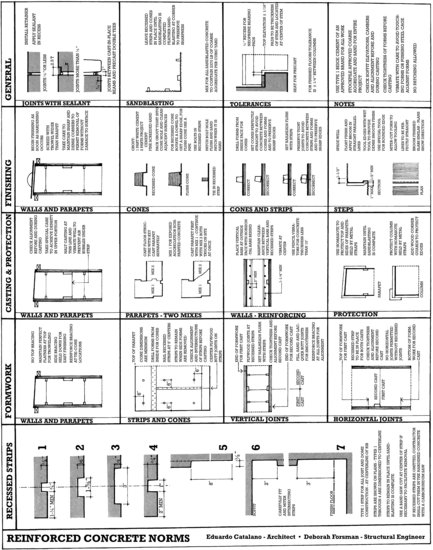
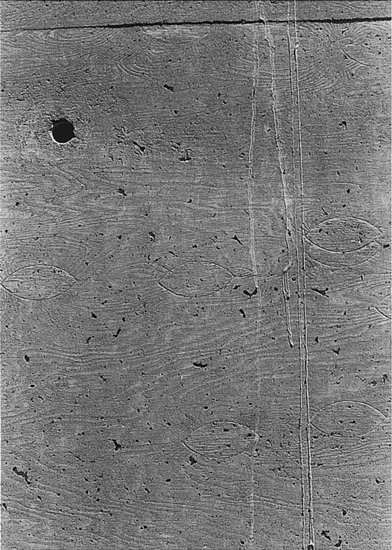
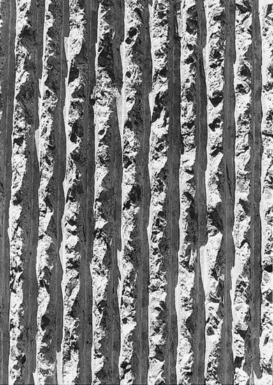
Figure 14.49 Close-up photographs of some surface textures for exposed concrete walls. (a) Concrete cast against overlaid plywood to obtain a very smooth surface shows a crazing pattern of hairline cracks after 10 years of service. (b) The boat-shaped patches and rotary-sliced grain figure of A-veneered plywood formwork are mirrored faithfully in this surface. A neatly plugged form tie hole is seen at the upper left, and several lines of overspill from a higher pour have dribbled over the surface. (c) This exposed aggregate surface was obtained by coating the formwork with a curing retarder and scrubbing the surface of the concrete with water and a stiff brush after stripping the formwork. (d) The bush-hammered surface of this concrete column is framed by a smoothly formed edge. (e, f ) Architect Paul Rudolph developed the techniques of casting concrete walls against ribbed formwork, then bush-hammering the ribs to produce a very heavily textured, deeply shadowed surface. In (f ), the ribbed wall surface is contrasted to a board-formed slab edge, with a recessed rustication strip between. (Photos by Edward Allen.)
(a)

(b)
(c)

(d)

(e)
(f)

Exposed wall surfaces of concrete require special attention from the designer and contractor (Figure 14.48). The chairs and bolsters selected must not create rust spots on exterior concrete surfaces. Form tie locations in exposed concrete walls should be patterned to harmonize with the layout of the walls themselves, and the holes left in the concrete surfaces by snapped-off ties must be patched or plugged securely to prevent rusting through. Joints between pours can be concealed gracefully with recesses called rustication strips in the face of the concrete. The formulation of the concrete must be closely controlled for color consistency from one batch to the next. In cold climates, air entrainment is advisable to prevent freeze-thaw damage of exterior wall surfaces.
Figure A A diamond saw blade is made up of cutting segments brazed to a steel blade core. Each segment consists of diamond crystals embedded in a metallic bonding matrix. The diamonds in the cutting segment fracture chips from the material being cut. In doing so, each diamond gradually becomes chipped and worn and finally falls out of the matrix altogether. The bonding matrix wears at a corresponding rate, exposing new diamonds to take over for those that have fallen out.

Figure B A hand-held pneumatically powered diamond circular saw cuts excess length from a concrete pile. (Courtesy of Sinco Products, Inc.)
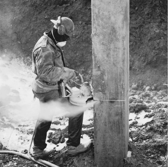
Figure C A diesel-powered diamond circular saw slices a clean joint at the edge of a concrete pavement. (Copyright © 2013 Husqvarna AB (Publ). All rights reserved.)

Figure D Cutting a new opening in a masonry wall with a diamond circular saw. (Copyright © 2013 Husqvarna AB (Publ). All rights reserved.)

Figure E This remote-controlled wall saw is powered by a water-cooled electric motor and can make cuts up to 29 in. (730 mm) deep. (Copyright © 2013 Husqvarna AB (Publ). All rights reserved.)
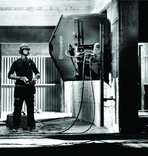
Figure F A hydraulically driven chain saw with diamond teeth cuts a concrete masonry wall. (C-150 Hydracutter, photo courtesy of Reimann & George Construction, Buffalo, NY.)

Figure G A diamond core drill is used for cutting round holes. (Photo courtesy of Sprague & Henwood, Inc.—Scranton, PA, USA.)

Figure H Using a technique called stitch drilling, a core drill cuts an opening in a very thick concrete wall. (Courtesy of GE Superabrasives.)
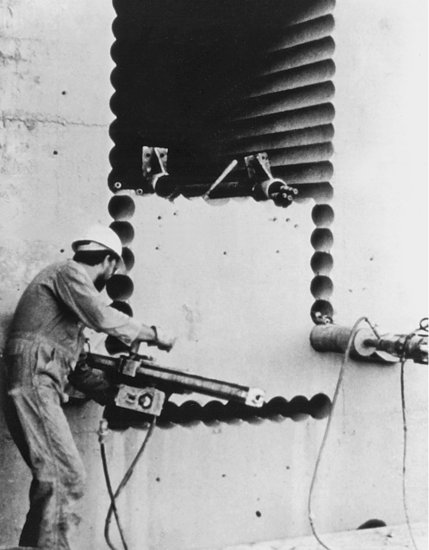
Figure I Sawed and drilled openings for utility lines in a concrete floor slab. (Courtesy of GE Superabrasives.)

Figure J Wire saws are capable of cutting depths and thicknesses of material that cannot be cut with any other kind of tool. Holes are first drilled at the corners of the cut, and the diamond cutting wire is strung through the holes and around the wheels of the sawing equipment. The saw maintains a constant tension on the wire as it is pulled at high speed through the material. The wire gradually cuts its way out, leaving smooth planar surfaces. The wire is actually a steel cable on which steel beads with diamonds embedded in them are strung. (© 1988 Cutting Technologies, Inc. (Cincinnati, Ohio). All rights reserved.)

Basically there are two approaches to the problem of producing a good surface finish on concrete. One is to remove the cement that is the cause of the blemishes and expose the aggregate. The other is to superimpose a pattern or profile that draws attention from the blemishes.
—Henry Cowan, Science and Building: Structural and Environmental Design in the Nineteenth and Twentieth Centuries, Hoboken, NJ, John Wiley & Sons, Inc., 1978, p. 283
LONGER SPANS IN SITECAST CONCRETE
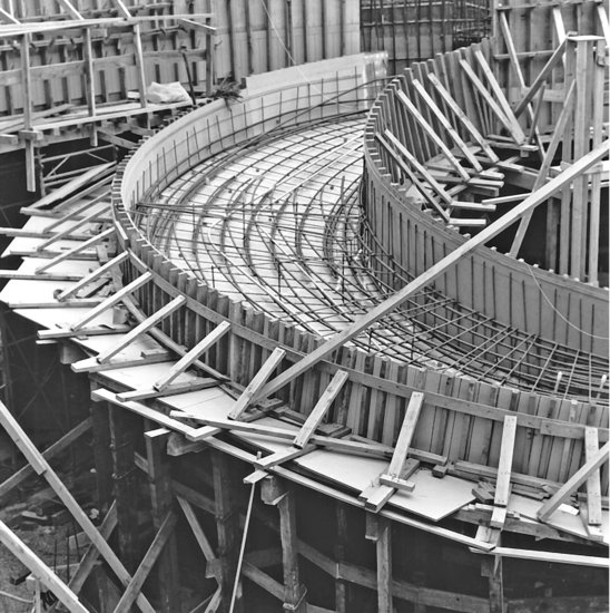
The ancient Romans built unreinforced concrete vaults and domes as roofs for temples, baths, palaces, and basilicas (Figure 13.2). Impressive spans were constructed, including a dome over the Pantheon in Rome, still standing, that approaches 150 feet (45 m) in diameter. Today, the arch, dome, and vault remain favorite devices for spanning long distances in concrete because of concrete's suitability to structural forms that work entirely in compression (Figures 14.50, 14.51, and 14.52). Through folding or scalloping of vaulted forms, or through the use of warped geometries such as the hyperbolic paraboloid, the required resistance to buckling can be achieved with a surprisingly thin layer of concrete, often proportionally thinner than the shell of an egg (Figure 14.52b).
Figure 14.50 The same wooden centering was used four times to form this concrete arch bridge. (Courtesy of Gang-Nail Systems, Inc.)
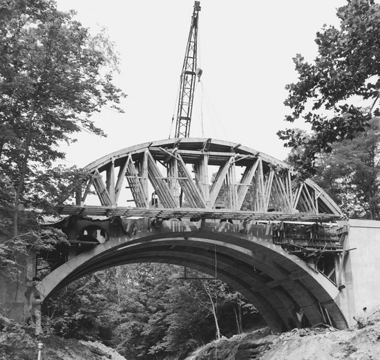
Figure 14.51 Examples of eight types of longer-span structures in concrete. Each is a special case of an infinite variety of forms. All can be sitecast, but the rigid frame, space frame, and Vierendeel truss are more likely to be precast for most applications.


Figure 14.52 Three concrete shell structures by 20th-century masters of concrete engineering. (a) A domed sports arena by Pier Luigi Nervi. (b) A lakeside restaurant of hyperbolic paraboloid shells by Felix Candela. (c) A racetrack grandstand roofed with cantilevered concrete barrel shells by Eduardo Torroja. (Drawings by Edward Allen.)
(a)

(b)

(c)

Long-span beams and trusses are possible in concrete, including posttensioned beams and girders and reinforced deep girders analogous to steel plate girders and rigid frames. Concrete trusses and space frames are not common, but are built from time to time. By definition, a truss includes strong tensile forces as well as compressive forces and is heavily dependent on steel reinforcing or prestressing.
Barrel shells and folded plates (Figures 14.51, 14.52c, and 14.53) derive their stiffness and strength from the folding or scalloping of a thin concrete plate to increase its rigidity and structural depth without adding material. Each of these forms depends on reinforcing or posttensioning to resist the tensile forces that it may experience.
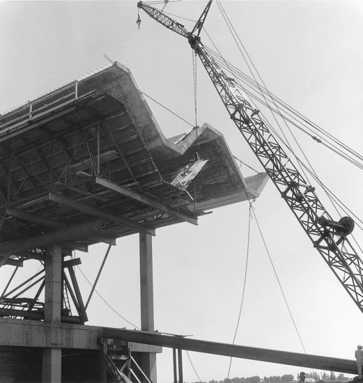
Figure 14.53 Flying formwork is removed from a bay of a folded plate concrete roof for an air terminal. (Architects: Thorshov and Cerny. Courtesy American Plywood Association.)
DESIGNING ECONOMICAL SITECAST CONCRETE BUILDINGS
The cost of a concrete building frame can be broken down into the costs of the concrete, the reinforcing steel, and the formwork. Of the three, the cost of concrete is usually the least significant in North America and the cost of formwork is the most significant. Accordingly, simplification and standardization of formwork are the first requirements for an economical concrete frame. Repetitive, identical column spacings and bay sizes allow the same formwork to be used again and again without alterations. Flat plate construction is often the most economical, simply because its formwork is so straightforward. Joist band construction is usually more economical than joist construction that uses beams proportioned more efficiently for their structural requirements, because enough is saved on formwork costs to more than compensate for the added concrete and reinforcing steel in the beams. This same reasoning applies if column and beam dimensions are standardized throughout the building, even though loads may vary; the amount of reinforcing and the strengths of the concrete and reinforcing steel can be adjusted to meet the varying structural requirements (Figure 14.54).
Figure 14.54 By keeping sizes of columns, beams, and other formed elements as consistent as possible, significant savings can be achieved in the cost of formwork for sitecast concrete construction. Here, a column form, having been stripped from a recently cast column, is being moved to a new location for reuse. (Photo by Joseph Iano.)

Figure 14.55 Concrete work nears the 1475-foot (450-m) summit of the twin Petronas Towers in Kuala Lumpur, Malaysia, which were, at the time of their construction, the world's tallest buildings. Each tower is supported by a perimeter ring of 16 cylindrical concrete columns and a central core structure, also made of concrete. The columns vary in diameter from 8 feet (2400 mm) at the base of the building to 4 feet (1200 mm) at the top. For speed of construction, the floors were framed with steel and composite metal decking. Concrete with strengths as high as 11,600 psi (80 MPa) was used in the columns. The architect was Cesar Pelli & Associates, Inc. The structural engineers were Thornton-Tomasetti and Rahnill Bersekutu Sdn Bhd. The U.S. partner in the joint venture team that constructed the towers was J. A. Jones Construction Co. of Charlotte, North Carolina. (Photograph by Uwe Hausen, J. A. Jones, Inc.)

SITECAST CONCRETE AND THE BUILDING CODES
Concrete structures are inherently fire resistant. When fire attacks concrete, the water of hydration is gradually driven out and the concrete loses strength, but this deterioration is slow because considerable heat is needed to raise the temperature of the mass of concrete to the point where dehydration begins, and a large additional quantity of heat is required to vaporize the water. The steel reinforcing bars or prestressing strands are buried beneath a concrete cover that protects them for an extended period of time. Except under unusual circumstances, such as a prolonged fire fueled by stored petroleum products, concrete structures usually survive fires with only cosmetic damage and are repaired with relative ease.
Concrete structures with adequate cover over reinforcing and adequate slab thicknesses are classified as Type I buildings under the International Building Code. Slab thickness requirements for the several construction types are complex, depending on the type of aggregate used in the concrete and whether or not a given structural member is restrained from movement by surrounding construction. Fire resistance requirements for the highest construction types can be met in joist and waffle systems either by increasing their slab thickness beyond what is structurally necessary or by applying fireproofing materials to the lower surfaces of the floor structures.
Sitecast concrete buildings have rigid joints and in many cases require no additional structural elements to achieve the necessary resistance to wind and seismic forces. More restrictive seismic design provisions in the building codes have, however, increased the attention paid by structural engineers to column ties and beam stirrups, particularly in the zones where beams and columns meet, to be sure that vertical bars in columns and horizontal bars in beams are adequately restrained against the greater forces that can occur in these zones under seismic loadings. The joints between flat plate floors and columns may not be sufficiently rigid to brace a building of more than modest height, unless drop panels or beams are added to stiffen the slab-to-column junction.
UNIQUENESS OF SITECAST CONCRETE
Concrete is a shapeless material that must be given form by the designer. For economy, the designer can adopt a standard system of concrete framing. For excitement, one can invent new shapes and textures. Some have pursued its sculptural possibilities, others its surface patterns and textures, still others its structural logic. From each of these routes have come masterpieces—Le Corbusier's chapel at Ronchamp (Figure 14.59); Wright's Unity Temple (Figure 14.1); and the elegant structures of Torroja, Candela, and Nervi, examples of which are sketched in Figure 14.52. Many of these masterpieces, especially from the latter three designers, were also constructed with impressive economy. Sitecast concrete can do almost anything, be almost anything, at almost any scale, and in any type of building. It is a potent architectural material, and therefore a material both of spectacular architectural achievements and dismal architectural failures. A material that is so malleable demands skill and restraint from those who would build with it, and a material so commonplace requires imagination if it is to rise above the mundane.
Figure 14.56 The plastered surfaces of Frank Lloyd Wright's Guggenheim Museum (1943–1956) cover a helical ramp of cast-in-place concrete. (Photo by Wayne Andrews.)

Figure 14.57 The Chapel of St. Ignatius, Seattle University, designed by architect Steven Holl, is a tilt-up concrete structure. (Photo by Joseph Iano.)

Figure 14.58 A sitecast concrete house in Lincoln, Massachusetts. (Architects: Mary Otis Stevens and Thomas F. McNulty.)

Figure 14.59 Le Corbusier's most sculptural building in his favorite material, concrete: the chapel of Notre Dame de Haut at Ronchamp, France (1950–1955). (Drawing by Edward Allen.)

Figure 14.60 The TWA Terminal at John F. Kennedy Airport, New York, 1956–1962. (Architect: Eero Saarinen. Photo by Wayne Andrews.)


KEY TERMS
REVIEW QUESTIONS
1. Draw from memory a detail of a typical slab on grade and list the steps in its production.
2. Why can't the surface of a slab on grade be finished in one operation, instead of waiting for hours before final finishing?
3. What are control joints and isolation joints? Explain the purpose and typical locations for each in a concrete slab.
4. List the steps that are followed in forming and pouring a concrete wall.
5. Distinguish one-way concrete framing systems from two-way systems. Are steel and wood framing systems one-way or two-way? Is one-way construction more efficient structurally than two-way construction?
6. List the common one-way and two-way concrete framing systems and indicate the possibilities and limitations of each.
7. Why posttension a concrete structure rather than merely reinforce it?
EXERCISES
1. Propose a suitable reinforced concrete framing system for each of the following buildings and determine an approximate thickness for each:
a. An apartment building with a column spacing of about 16 feet (5 m) in each direction
b. A newsprint warehouse, column spacing 20 feet by 22 feet (6 m × 6.6 m)
c. An elementary school, column spacing 24 feet by 32 feet (7.3 m × 9.75 m)
d. A museum, column spacing 36 feet by 36 feet (11 m × 11 m)
e. A hotel where overall building height must be minimized in order to build as many stories as possible within a municipal height limit
2. Look at several sitecast concrete buildings. Determine the type of framing system used in each and explain why you think it was selected. If possible, talk to the designers of the building and find out if you were right.
3. Observe a concrete building under construction. What is its framing system? Why? What types of forms are used for its columns, beams, and slabs? In what form are the reinforcing bars delivered to the site? How is the concrete mixed? How is it raised and deposited into the forms? How is it consolidated in the forms? How is it cured? Are samples taken for testing? How soon after pouring are the forms stripped? Are the forms reused? How long are the shores kept in place? Keep a diary of your observations over a period of a month or more.
SELECTED REFERENCES
See also the Selected References listed in Chapter 13.
American Concrete Institute. ACI 303R: Guide to Cast-in-Place Architectural Concrete Practice. Farmington Hills, MI, updated regularly.
This is a comprehensive handbook on how to produce attractive surfaces in concrete.
American Concrete Institute. ACI 318: Building Code Requirements for Structural Concrete and Commentary. Farmington Hills, MI, updated regularly.
This booklet establishes the basis for the engineering design and construction of reinforced concrete structures in the United States.
Concrete Reinforcing Steel Institute. CRSI Design Handbook. Schaumburg, IL, Author, updated regularly.
Structural engineers working in concrete use this handbook, which is based on the ACI Code, as their major reference. It contains examples of engineering calculation methods and hundreds of pages of tables of standard designs for reinforced concrete structural elements.
Concrete Reinforcing Steel Institute. Placing Reinforcing Bars. Schaumburg, IL, Author, updated regularly.
Written as a handbook for those engaged in the business of fabricating and placing reinforcing steel, this small volume is clearly written and beautifully illustrated with diagrams and photographs of reinforcing for all the common concrete framing systems.
Hurd, M. K. Formwork for Concrete (7th ed.). Farmington Hills, MI, American Concrete Institute, 2005.
Profusely illustrated, this book is the bible on formwork design and construction for sitecast concrete.
Post-Tensioning Institute. Post-Tensioning Manual. Phoenix, AZ, Author, updated regularly.
This heavily illustrated volume is both an excellent introduction to posttensioning for the beginner and a basic engineering manual for the expert.
WEB SITES
Sitecast Concrete Framing Systems
Author's supplementary web site: www.ianosbackfill.com/14_sitecast_concrete_framing_systems
Dayton Superior formwork accessories: www.daytonsuperior.com
Dywidag-Systems International posttensioning systems: www.dsiamerica.com
Molded Fiber Glass Construction Products Co. formwork: www.mfgcp.com