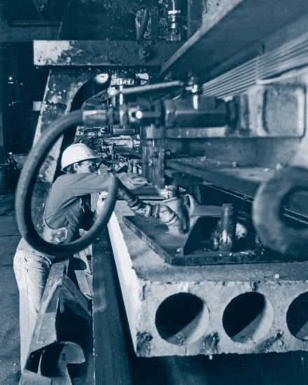
Suction devices lift a precast concrete hollow-core slab from the casting bed where it was manufactured. (Courtesy of The Flexicore Co., Inc.)
15
PRECAST CONCRETE FRAMING SYSTEMS
Precast, Prestressed Concrete Structural Elements
Precast Concrete Beams, Girders, and Columns
Assembly Concepts for Precast Concrete Buildings
Manufacture of Precast Concrete Structural Elements
Prestressing and Reinforcing Steel
Joining Precast Concrete Members
Composite Precast/Sitecast Concrete Construction
Precast Concrete and the Building Codes
Uniqueness of Precast Concrete
Figure 15.1 A fully precast building frame under construction. A poured concrete topping will cover the hollow-core slabs and the beams to create a smooth floor and tie the precast elements together. (Courtesy of The Flexicore Co., Inc.)
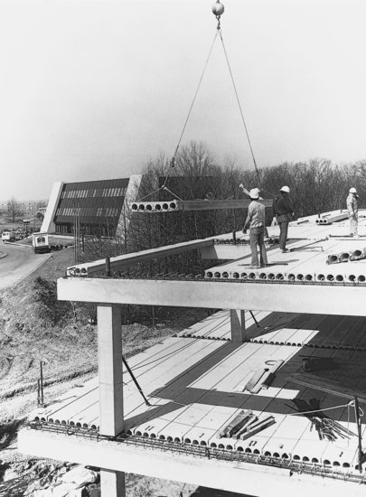
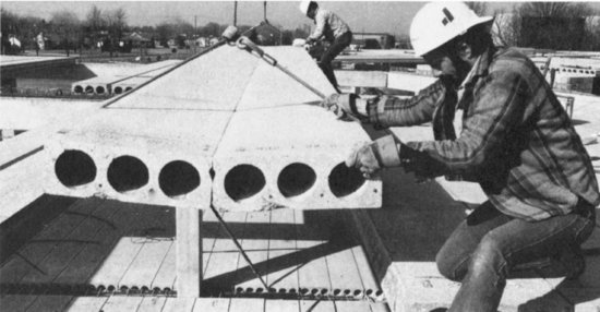
Figure 15.2 Workers guide two hollow-core slabs, lowered by a crane in wire rope slings, onto the precast concrete beams that will support them. (Courtesy of The Flexicore Co., Inc.)
PRECAST, PRESTRESSED CONCRETE STRUCTURAL ELEMENTS
Precast Concrete Slabs
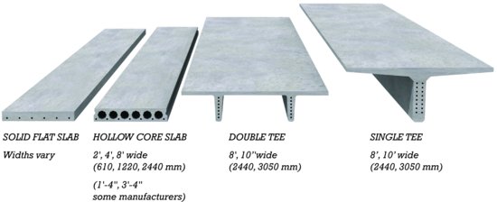
The most fully standardized precast concrete elements are those used for making floor and roof slabs (Figure 15.3). These may be supported by bearing walls or frames made of precast concrete, sitecast concrete, masonry, or steel. Four kinds of precast slab elements are commonly produced: For short spans and minimum slab depths, solid slabs are appropriate. For longer spans, deeper elements must be used, and precast solid slabs, like their sitecast counterparts, become inefficient because they contain too much deadweight of nonworking concrete. In hollow-core slabs, precast elements suitable for intermediate spans, internal longitudinal voids replace much of the nonworking concrete. For the longest spans, still deeper elements are required, and double tees and single tees eliminate still more nonworking concrete.
Figure 15.3 The four major types of precast concrete slab elements. Hollow-core slabs are produced by different companies in a variety of cross-sectional patterns, using several different processes.
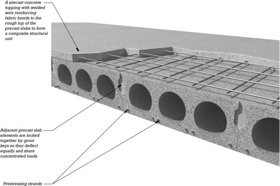
For most applications, precast slab elements are manufactured with a rough top surface. After they have been erected, a concrete topping is poured over them and finished to a smooth surface. The topping, usually 2 inches (50 mm) thick, bonds during curing to the rough surface of the precast elements and becomes a working part of their structural action. The topping also helps the precast elements to act together as a structural unit, rather than as individual planks, in resisting concentrated loads and diaphragm loads, and it conceals the slight differences in camber that often occur in prestressed components. Structural continuity across a number of spans can be achieved by casting reinforcing bars into the topping over the supporting beams or walls. Underfloor electrical conduits may also be embedded in the topping. Smooth-top precast slabs are sometimes used without topping, as is discussed later in this chapter.
Either normal-density concrete or structural lightweight concrete may be selected for use in any of the precast slab elements. Lightweight concrete, approximately 20 percent less dense than normal concrete, reduces the load on the frame and foundations of a building but is more expensive than normal-density concrete.
There is considerable overlap in the economical span ranges of the different kinds of precast slab elements, allowing the designer some latitude in choosing which to use in a particular situation. Solid slabs and hollow-core slabs save on overall building height in multistory structures, and their smooth undersides can be painted and used as finish ceilings in many applications. For longer spans, double tees are preferred to the older single-tee design because they need not be supported against tipping during erection, allowing the construction to proceed more quickly and at less cost.
Precast Concrete Beams, Girders, and Columns
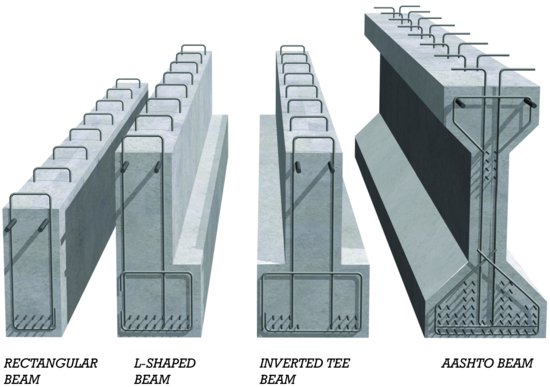
Precast concrete beams and girders are made in several standard shapes (Figure 15.4). The projecting ledgers on L-shaped beams and inverted tees provide direct support for precast slab elements. They conserve headroom in a building by supporting slabs near the bottoms of the beams, allowing the beam and slab to share some of the same structural depth. Precast concrete columns are usually square or rectangular in section and may be prestressed or simply reinforced.
Figure 15.4 Standard precast concrete beam and girder shapes. The heavier bars near the tops of the beams are mild steel reinforcing, and the smaller strands near the bottom are high-strength prestressing. Mild steel stirrups are also shown. Stirrups usually project above the top of the beam, as shown, to bond to a sitecast concrete topping, creating composite structural action. AASHTO (American Association of State Highway and Transportation Officials) beams were designed originally as efficient shapes for bridge structures. They have also found occasional use in parking garage structures or other utilitarian building types.
- Estimate the depth of a precast solid slab at 1/40 of its span. Depths typically range from 3½ to 8 inches (90–200 mm).
- An 8-inch (200-mm) precast hollow-core slab can span approximately 25 feet (7.6 m), a 10-inch (250-mm) slab 32 feet (9.8 m), and a 12-inch (300-mm) slab 40 feet (12 m).
- Estimate the depth of precast concrete double tees at 1/28 of their span. The most common depths of double tees are 12, 14, 16, 18, 20, 24, and 32 inches (300, 350, 400, 460, 510, 610, and 815 mm). Some manufacturers can provide double tees that are 48 inches (1220 mm) deep.
- A precast concrete single tee 36 inches (915 mm) deep spans approximately 85 feet (926 m) and a 48-inch (1220-mm) tee 105 feet (32 m).
- Estimate the depth of precast concrete beams and girders at 1/15 of their span for light loadings and 1/15 of their span for heavy loadings. These ratios apply to rectangular, inverted-tee, and L-shaped beams. The width of a beam or girder is usually about one-half of its depth. The projecting ledgers on inverted-tee and L-shaped beams are usually 6 inches (150 mm) wide and 12 inches (300 mm) deep.
- To estimate the size of a precast concrete column, add up the total roof and floor area supported by the column. A 10-inch (250-mm) column can support up to about 2300 square feet (215 m2) of area, a 12-inch (300-mm) column 3000 square feet (280 m2), a 16-inch (400-mm) column 5000 square feet (465 m2), and a 24-inch (600-mm) column 9000 square feet (835 m2).
Precast Concrete Wall Panels
Precast concrete panels, either prestressed or conventionally reinforced, are used as loadbearing wall panels in many types of low-rise and high-rise buildings. Solid panels range from 3½ to 10 inches (90 to 250 mm) in thickness and can span one or two stories in height. When prestressed, strands are located in the vertical midplane of the wall panels to strengthen the panels against buckling and to eliminate camber. Ribbed or hollow-core panels, or sandwich panels with integral rigid foam insulation, may be as deep as 12 to 24 inches (305 to 610 mm) and can span up to four stories (Figure 15.12).
A number of manufacturers produce proprietary precast concrete wall panels for residential foundation construction. Vertical ribs, so-called concrete studs, spaced at 24 inches (610 mm), provide faces with sheet metal or wood strips for the attachment of interior finishes and create cavity space that can accommodate insulation or the routing of services. Some manufacturers integrate rigid foam insulation or reinforced footings into the design of the panels.
Nonloadbearing precast concrete wall panels, called architectural precast concrete, are discussed in Chapter 20.
ASSEMBLY CONCEPTS FOR PRECAST CONCRETE BUILDINGS
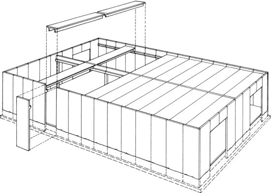
Figure 15.5 shows a building whose precast slab elements (double tees in this example) are supported on a skeleton frame of L-shaped precast girders and precast columns. The slab elements in Figure 15.6 are supported on precast loadbearing wall panels. Figure 15.7 illustrates a building whose slabs are supported on a combination of wall panels and girders. These three fundamental ways of supporting precast slabs—on a precast concrete skeleton, on precast loadbearing wall panels, and on a combination of the two—occur in endless variations in buildings. The skeleton may be one bay or many bays deep; the loadbearing walls are often constructed of reinforced masonry or of various configurations of precast concrete; the slab elements may be solid, hollow-core, or double tee, topped or untopped. One of the principal virtues of precast concrete as a structural material is that it is locally manufactured to order and is easily customized to an individual building design, usually at minimal additional cost.
Figure 15.5 Double-tee slab elements supported on a frame of precast columns and L-shaped girders. (Courtesy of Precast/Prestressed Concrete Institute.)

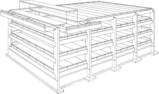
Figure 15.6 Hollow-core slab elements supported on precast concrete loadbearing wall panels. (Courtesy of Precast/Prestressed Concrete Institute.)
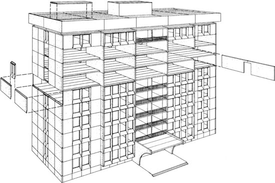
Figure 15.7 Double-tee slab elements supported on a perimeter of precast concrete loadbearing wall panels and an interior structure of precast columns and inverted tee beams. (Courtesy of Precast/Prestressed Concrete Institute.)
MANUFACTURE OF PRECAST CONCRETE STRUCTURAL ELEMENTS
Casting Beds
Most precast concrete elements are produced in permanent forms called casting beds. Casting beds average 400 feet (125 m) in length but extend 800 feet (250 m) or more in some plants (Figure 15.8). A cycle of precasting usually begins in the morning, as soon as the elements that were cast the previous day have been lifted from the beds. High-strength steel reinforcing strands are strung between the abutments at the extreme ends of the bed. The strands are pretensioned with hydraulic jacks, during which process they stretch considerably. Once the strands are fully tensioned, transverse bulkhead separators may be placed along the bed at the required intervals to divide the individual elements from one another. (For solid slabs, cored slabs, and wall panels, the bulkheads are often omitted; the cured slab or panel is simply sawed into the required lengths before it is removed from the bed.)
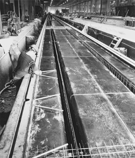
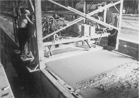
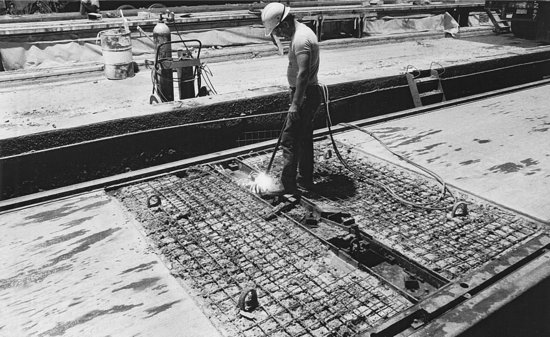
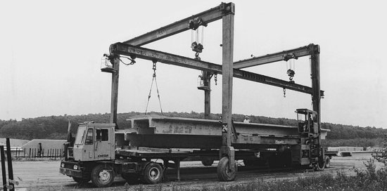
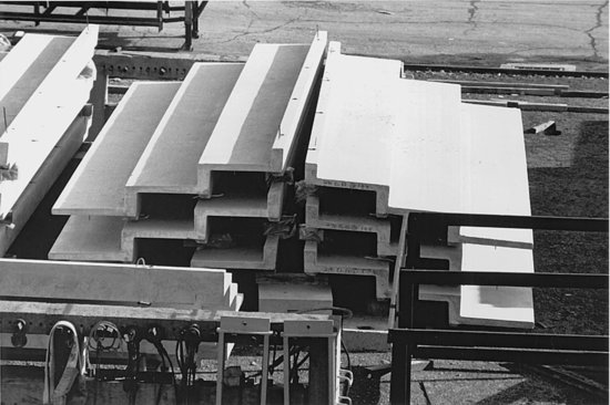
Figure 15.8 Manufacturing double-tee slabs. (a) A worker inserts weld plates with their V-shaped anchors of reinforcing bar in the casting bed prior to pouring the concrete. The prestressing strands and wire fabric shear reinforcement have been installed in the stems of the double tees, and a portion of the welded wire fabric for the top slab can be seen in the foreground. Notice the great length of the casting bed; many elements can be cast end to end at the same time. (b) The top surface of the concrete is straightedged by machine. (c) The next morning, following overnight steam curing, a worker cuts the prestressing strands between bulkhead separators with an oxyacetylene cutting torch. The welded wire fabric is exposed at the ends of the elements because they will be used as untopped slabs (see Figure 15.20). (d) Using lifting loops cast into the ends, the slabs are lifted from the bed and stockpiled outdoors. The dapped stems will rest on inverted-tee and L-shaped girders; the notched corner will fit around a column. (e) Loading the double tees for trucking. (Photos by Alvin Ericson.)
(a)
(b)
(c)
(d)

(e)
When pretensioning and separator placement have been completed, mild steel reinforcing bars and welded wire fabric are placed as required. Weld plates and other embedments are installed. Then the concrete is placed in the bed, vibrated to eliminate voids, and struck off level. If the slabs are to be used without topping, the top surface is finished further with floats and trowels. Live steam or radiant heat is then applied to the concrete to accelerate its curing. Ten to twelve hours after pouring, the concrete has reached a compressive strength of 2500 to 4000 psi (24–28 MPa) and has bonded to the steel strands. The next morning, after the strength of the concrete has been verified by testing cylinders in the laboratory, the exposed strands are cut between the bulkhead separators, releasing the external force in the strands, which spring back to prestress the concrete. Asymmetrically prestressed slab and beam elements immediately arch up from the casting bed to take on a pronounced camber as the prestressing force is released into them. When the elements have been separated from one another, they are hoisted off the bed and stockpiled ready for shipment. Then a new cycle of casting begins.
Prestressing and Reinforcing Steel
Solid slabs, hollow-core slabs, and wall panels are cast around horizontal strands. Tees, double tees, beams, and girders are often cast around depressed or harped strands for greater efficiency of structural action (Figures 13.42 and 15.9).
Figure 15.9 A precasting bed being readied for the pouring of a very long AASHTO girder. Side forms for the mold can be seen in the background to the right. The depressed strands are held down in the center of the beam by steel pulleys that will be left in the concrete after pouring. The bed is long enough that several girders are being cast end to end, with the depressed strands pulled up and down as required. Mild steel reinforcing bars are used for stirrups. The projecting tops of the stirrups will bond to the sitecast topping. Vertical twists of prestressing strand near the end of the girder will serve as lifting loops. (Courtesy of Blakeslee Prestress, Inc.)
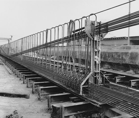
Ordinary mild steel reinforcing is also cast into prestressed concrete elements for various purposes: Beams or slabs that will cantilever beyond their supports are given top reinforcing bars over the cantilever points. Welded wire reinforcing is used to reinforce the flanges of tees and double tees and for general reinforcing of wall panels. Where stirrups are required in the stems of beams and single or double tees, they are made of either mild steel reinforcing bars or welded wire reinforcing (Figure 15.10). Additional reinforcing may be installed to add strength around dapped (notched) ends and openings in panels or slabs for pipes, ducts, columns, and hatchways. Weld plates and other metal connecting devices are cast into the elements as required. Projecting steel loops are cast into many types of elements as crane attachments for lifting.
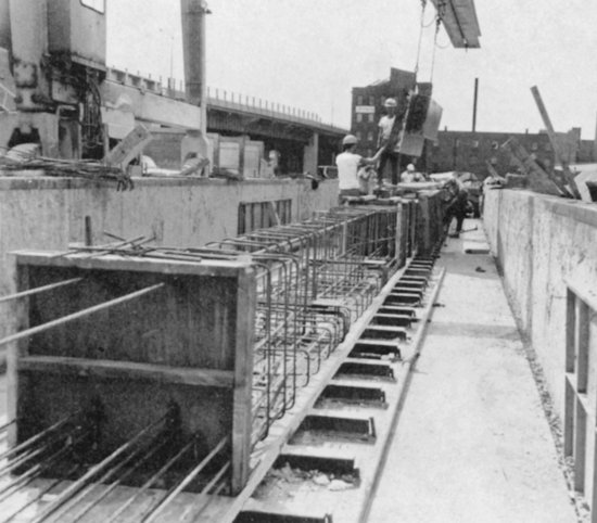
Figure 15.10 Workers install side forms for inverted-tee beams in an outdoor casting bed. Mild steel reinforcing bars are used extensively for stirrups. (Courtesy of Blakeslee Prestress, Inc.)
Carbon Fiber Reinforcing
Carbon fiber reinforcing is gaining use as a substitute for mild steel reinforcing, such as for shear stirrups and temperature steel, in precast concrete products including wall panels, double tees, and deck panels for floors and roofs. Because carbon fiber, unlike steel, does not require protection from corrosion, less concrete cover is required than for steel reinforcing, significantly reducing the overall thickness and weight of carbon fiber–reinforced components. The low thermal conductivity of carbon fiber, combined with the thinner concrete sections possible with this type of reinforcing, permit the casting of insulated panels with superior thermal performance. The much higher tensile strength and stiffness of carbon fiber in comparison to mild steel, and the innovative ways in which grids of carbon fiber reinforcing can be integrated into precast concrete components, yield improvements in structural efficiency as well.
Carbon fiber composite cable substitutes for high-strength steel posttensioning strands are finding use in experimental precast concrete highway structures. It is likely that these materials will eventually enter the building construction market as well.
Hollow-Core Slab Production
The longitudinal voids in hollow-core slabs can be formed by a number of processes. In the extruded process, extrusion devices squeeze an extremely dry, stiff concrete mix through a moving extrusion die to produce the voided shape directly. This method has the disadvantage that vertical openings and weld plates cannot easily be cast in; where openings are required in extruded slabs, they must be cut out of the stiff but still wet concrete just after extrusion or sawed after curing (Figure 15.11). Weld plates are added to the slabs by hand before the concrete has completely cured. In the wet-cast process, a bottom layer of wet concrete is deposited in the casting bed; then a second layer of concrete, with collapsible tubes, dry crushed stone, or lightweight aggregate carefully positioned to form the voids, is placed. Special forms may easily be placed in the bed to make openings as required, and weld plates may be cast in by this process. The tubes or aggregate are removed after the concrete has cured. In the slip-form process, a moving hopper deposits a zero-slump concrete mix in the casting bed. Tubes that form the slab cores move with the hopper and are pulled out of the slab as the casting process proceeds from one end of the slab to the other. This process falls somewhere between the wet-cast and extrusion processes in terms of the relative ease or difficulty of placing embeds and forming special openings.
Figure 15.11 Steps in the manufacture of Span-Deck, a proprietary hollow-core slab. (A) A thin bottom slab of low-slump concrete is deposited into the casting bed with a traveling hopper. (B) A ridged roller compacts the bottom slab and makes indentations to key to the concrete webs. (C) Four prestressing strands are pulled onto the bed; these will be pretensioned with jacks. (D ) After pretensioning, an extrusion device travels the length of the bed, forming the webs and the top of the slab and filling the cores with dry, lightweight aggregate that serves as temporary support for the fresh concrete. (E) The next day, after curing of the slab has been completed, a saw cuts it into the required lengths. Each length is then lifted from the bed and transported by an overhead crane to the aggregate recovery area, where the dry aggregate is poured out and saved for reuse. (F ) Finished Span-Deck slabs stockpiled, ready for transportation to the construction site. The wads of paper in the cores prevent concrete from filling the cores during pouring of the topping. (Courtesy of Blakeslee Prestress, Inc.)
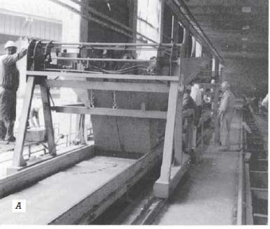

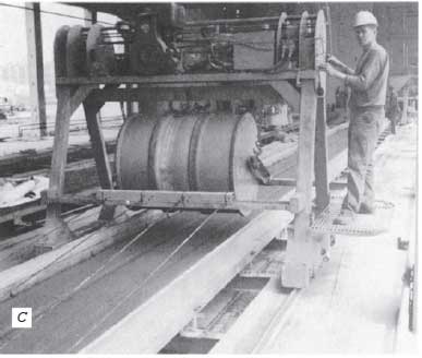


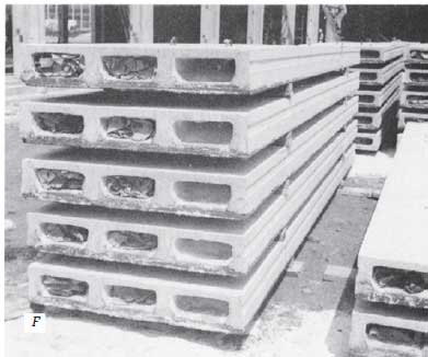
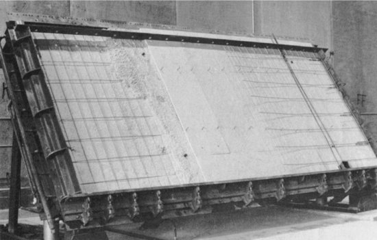
Figure 15.12 A tilting table being used for casting a foam-insulated concrete wall panel. To the left, a concrete panel face with welded wire fabric reinforcing is being cast. Sheets of rigid foam insulation with wire ties are seen in the center, and the welded wire fabric for the second panel face is seen at the right, with a pair of vertical bars and a pocket at the bottom being cast in as part of a system of connections. Notice the pipes at the left edge of the table for heating the mold to accelerate curing. (Courtesy of Blakeslee Prestress, Inc.)
After curing, the slabs are conveyed to an aggregate recovery area, where the dry stone is poured out of the voids and saved for reuse (Figure 15.11E). In another process, air-inflated tubes are used to form the voids. In some plants, hollow-core slabs are cast atop one another in stacks rather than in a single layer and are wet cured for 7 days rather than steam cured overnight.
Column Production
Precast concrete columns may be reinforced with ordinary mild steel or pretensioned strands. Pretensioned columns are often made and shipped in multistory lengths with corbels to support beams or slabs (Figures 15.16, 15.18). Columns with corbels on one side or on two opposing sides are easily cast in flat beds. If corbels are required on three sides or on two adjacent sides, box forms are set atop the upper side of the column form as it lies in the casting bed. For corbels on the fourth side, steel plate inserts are cast into the bottom face of the column in the bed, to which reinforcing bars are welded after the column is removed from the bed. The corbels on the fourth side are then cast around the reinforcing bars in a separate operation.
JOINING PRECAST CONCRETE MEMBERS
Figures 15.13 through 15.22 and 15.27 illustrate examples of frequently used connection details in precast concrete construction. Bolting, welding, and grouting are all commonly employed. Connections can be posttensioned to produce continuous beam action at points of support (Figure 15.16). Exposed metal connectors that are not covered by topping are usually dry packed with portland cement grout (the grout is stiff but not actually dry at the time that it is installed) after being joined to protect them from fire and corrosion.
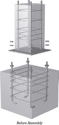
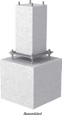
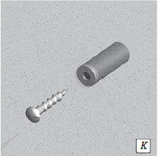
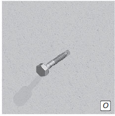
Figure 15.13 A simple base detail for precast concrete columns. Four anchor bolts project from the top of the sitecast foundation. Nuts and washers are placed on these bolts to support the column temporarily. The column, which was cast around steel dowels welded to a baseplate, is lowered by crane. Workers guide the column so that the anchor bolts come through the holes in the baseplate. Washers and nuts are added to the anchor bolts on top of the baseplate. The eight nuts are used to adjust the height of the column and to make it plumb. When this has been accomplished, the nuts are tightened and stiff grout is dry packed under the baseplate.

The simplest joints in precast concrete construction are those that rely on gravity by placing one element atop another, as is done where slab elements rest on a bearing wall or beam or where a beam rests on the corbel of a column. Column-to-footing or column-to-column joints are usually grouted, to allow full bearing between sections (Figures 15.13, 15.14, and 15.15). Bearing walls are joined with slabs in a similar manner (Figure 15.27). With spanning members, bearing pads are usually inserted at points of contact. These serve to avoid the grinding, concrete-to-concrete contact that might create points of high stress (Figures 15.16, 15.17, 15.18, and 15.19) while also allowing for movement caused by expansion and contraction or structural deflection of the members. For solid and hollow-core slabs, these pads are strips of high-density plastic. Under elements with higher point loadings, such as tees and beams, pads of synthetic rubber are used. For resistance to seismic and wind forces, the members in these simple joints must be tied together laterally. Slab elements are often joined over supports by reinforcing bars that are cast into the topping or, where no topping is used, into the grout keys between the slabs (Figures 15.18, 15.19, 15.20, 15.21, and 15.22). Beams, single tees, and double tees may additionally be connected by welding together steel plate inserts that have been embedded in the elements in the plant (Figures 15.18 and 15.19). The stems (lower portions) of single and double tees and the bottoms of beams are never welded to the supports, but are left free to move on their bearing pads as the slab elements deflect under load.
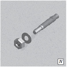
Figure 15.14 Similar details serve both as an alternative way of placing a column on its foundation and for column-to-column connections. Metal shims support the upper column sections at the proper height until the grout cures. The open corners are dry packed with stiff grout after the column has been aligned and bolted; this protects the metal parts of the connection from fire and corrosion.

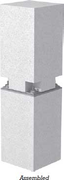
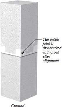
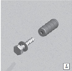
Figure 15.15 This column-to-column connection uses proprietary sleeves that are cast into the lower end of the upper column section. Before the sections are assembled (upper left), the lower ends of the vertical bars from the upper column section, which reach down to the midheight of each sleeve, are the only contents of the sleeves. Assembly of the column sections starts with the placement of a stack of steel shims in the center of the top of the lower section. These shims serve to adjust the height of the column and to maintain a space for grouting between the two sections. In the next two drawings, the sections have been assembled by lowering the upper section onto the lower one. The sleeves mate with projecting reinforcing bars from the lower column section. After the upper column section has been shimmed to exactly the right height and plumbed up, a fluid grout is injected into each sleeve, where it cures and serves to connect the reinforcing bars. A stiff grout is dry packed between the ends of the columns. The grouted sleeves develop the full strength of the reinforcing bars that they connect.
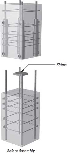
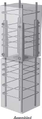

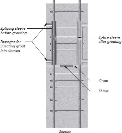
Figure 15.16 A posttensioned, structurally continuous beam–column connection may be created by passing a tendon from a pocket in the top of one beam, through the column, to a pocket in the top of the other beam. The tendon is anchored to a plate in one pocket as it is tensioned by a jack in the other pocket.
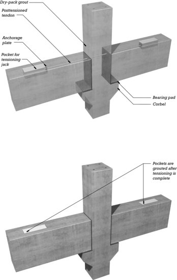
Figure 15.17 Topped hollow-core roof slabs supported on beams are joined to a column with vertical rods. A similar connection can be used for floor beams resting on corbels.
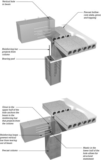
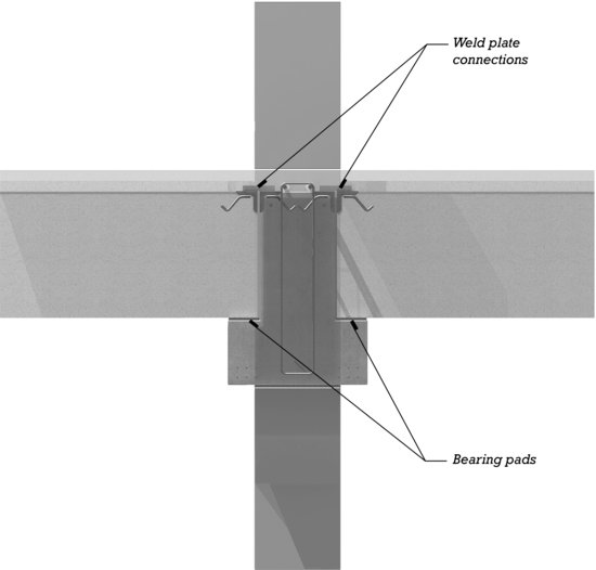
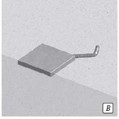
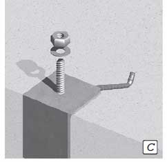
Figure 15.18 The beams in this system of framing rest on concrete corbels that are integrally cast with the column. The smooth-topped hollow-core slabs are detailed for use without topping. (a) Weld plates are cast into the column. (b) Beams are placed on bearing pads on the corbels. A weld plate is cast into the top of each beam at the end. (c) Short pieces of steel angle are welded to the plates to join the beams to the columns. Smooth-top hollow-core precast concrete planks are placed on bearing pads on top of each beam. Grout is poured into the gap between the ends of the planks to unite loops of reinforcing that project from the tops of the beams, reinforcing bars that are inserted through the loops, and lateral pieces of reinforcing bar that are grouted into the keys between planks. The end result is a tightly connected assembly that supports an untopped precast concrete floor or roof.
(a)

(b)
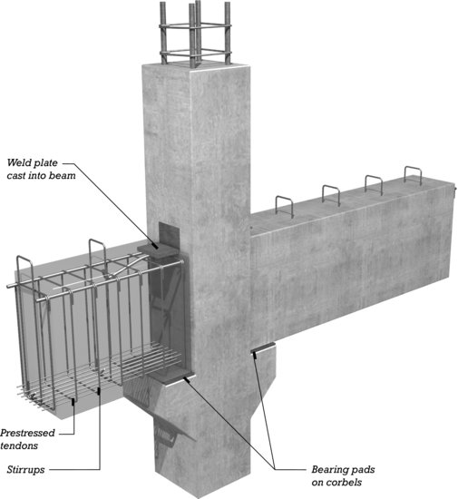
(c)
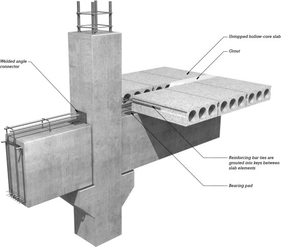
Figure 15.19 (a and b) Topped double-tee floor slabs are supported by inverted-tee beams in this detail. Reinforcing bars that pass through hollow tubes cast into the column connect the beams and column. (c) The sitecast topping ties all the components together and gives a smooth, level surface.
(a)

(b)

(c)


In some cases, precast slab elements, especially solid slabs, require temporary shoring at midspan to help support the weight of the topping until it has cured. After curing, the topping becomes part of the slabs and increases their strength and stiffness. For construction economy, smooth-topped precast slab elements are sometimes used without topping, especially for roofs, where any unevenness between elements is bridged by rigid thermal insulation placed on top. Untopped slabs may also be used for floors that will be finished with a pad and carpet and for parking garages. Untopped slabs require special connection details that do not rely on reinforcing bars placed in the topping (Figures 15.18 and 15.20).
Figure 15.20 A minimum-headroom, minimum-cost floor system for parking garages uses untopped double tees. Refer to Figure 15.8(c and d ) for photographs of how the ends of the tees are detailed for use in this system. The stems of the tees are dapped so that the beam need be no deeper than the tees.
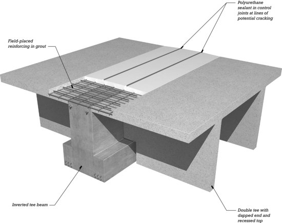
Figure 15.21 A cutaway view of a topped double-tee slab.
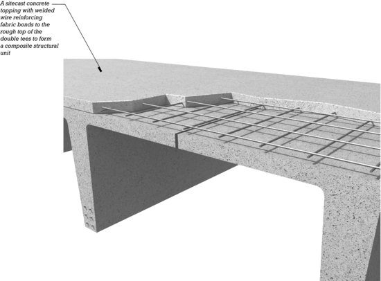
Figure 15.22 A cross section through a topped hollow-core slab.
Posttensioning can be used to combine large precast elements into even larger ones on the site. This is done to assemble precast concrete box segments into very long, deep girders for bridges (Figures 15.23 and 15.24) and to create tall shear walls from story-high precast panels in multistory buildings. In either case, ducts for the posttensioning tendons are placed accurately in the sections before casting so that they will mate perfectly end to end when the sections are assembled on the site. After assembly, tendons are inserted into the ducts, horizontally in the case of girders or vertically in the case of shear walls, tensioned with portable hydraulic jacks, then grouted if required.
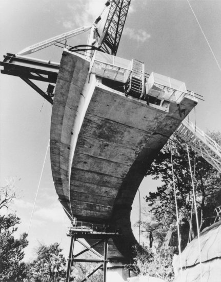
Figure 15.23 The Linn Cove Viaduct in Linnville, North Carolina, was built of short precast segments that were posttensioned together as they were placed to form a continuous box girder deck. A section is being installed by the derrick at the extreme right. The maximum clear span is 180 feet (55 m). (Engineer: Figg and Muller Engineers, Inc. Courtesy of Precast/Prestressed Concrete Institute.)

Figure 15.24 The Linn Cove Viaduct was constructed with very little temporary shoring so as to disrupt the natural landscape below as little as possible. The precast hollow box sections formed a girder that could cantilever for long distances during construction. The box profile is highly resistant to the torsional forces that occur in a curving beam. (Courtesy of Precast/Prestressed Concrete Institute.)
Joint design is the area in which precast concrete technology is developing most rapidly. Historically, precast concrete building construction has been limited in regions of high seismic risk due to uncertainty regarding the performance of this structure type under seismic loadings. More recently, innovations in the joining of precast concrete members have led to connection systems that can more reliably absorb the energy imparted into the structure during a seismic event. Unbonded posttensioning strands that allow the structure to respond elastically to seismic displacements, hybrid joint connections that combine the ductility of mild steel reinforcing with the high strength of prestressed strands, ungrouted or open joint systems that permit controlled movements between members, joint friction dampers that limit frame movements while absorbing seismic energy, and other techniques have come into use or are under development.
Other development efforts focus on improving the ease and economy of joining precast members. New joining systems are patented each year, and as reinforcing techniques, grouts, and adhesives develop further, there will be additional simplifications and improvements of many kinds in precast concrete framing details.
COMPOSITE PRECAST/SITECAST CONCRETE CONSTRUCTION
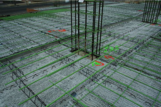
In the filigree precast concrete system, relatively thin precast elements that are either conventionally reinforced or prestressed are used as the formwork for site casting of beams and slabs. Once the process is complete, composite structural action between the sitecast concrete and precast units results in a unified, structurally efficient system. Because the precast units remain in place as part of the finished system, formwork costs are much less in comparison to conventional sitecast concrete construction methods (Figure 15.25).
Figure 15.25 In the filigree precast concrete system, precast concrete elements serve as formwork for sitecast concrete. In this photograph, precast units for a filigree slab and beam system have been erected and the placement of steel reinforcing is in progress. Later, concrete will be sitecast on top of this formwork. Once the construction of this system is complete, the precast units and sitecast concrete work together as a unified structural system: Prestressed strands in the precast units provide bottom reinforcing. Top bars are added on site as conventional reinforcing. Lightweight bar joist reinforcing, cast into the precast units so as to remain partially exposed, will form an intimate structural bond between the precast and sitecast concrete portions of the system, creating composite structural action in a manner very similar to that achieved with shear studs in structural steel composite construction (Figures 11.62 and 11.63). Note also the shallow slab band form running from lower left to upper right in this photograph. (Courtesy of Midstate Filigree Systems, www.filigreeinc.com.)
THE CONSTRUCTION PROCESS
The construction process for precast concrete framing is analogous to that for steel framing. The structural drawings for the building are sent to the precasting plant, where engineers and drafters prepare shop drawings that show all the dimensions and details of the individual elements and how they are to be connected. These drawings are reviewed by the engineer and architect for conformance with their design intentions and corrected as necessary. Then the production of the precast components proceeds, beginning with construction of any special molds that are required and fabrication of reinforcing cages, then continuing through cycles of casting, curing, and stockpiling as previously described. The finished elements, marked to designate their positions in the building, are transported to the construction site as needed and placed by crane in accordance with erection drawings prepared by the precasting plant (Figures 15.26 and 15.27).
Figure 15.26 A framing plan and elevation of a simple four-story building made of loadbearing precast concrete wall panels and hollow-core slab elements. (Courtesy of Precast/Prestressed Concrete Institute.)
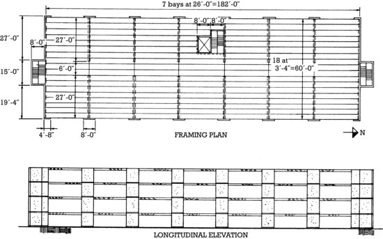
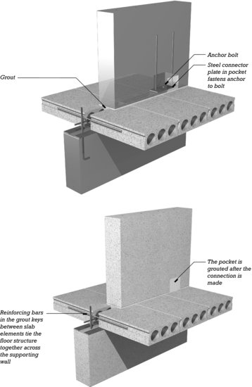
Figure 15.27 A typical detail for the slab–wall junctions in the structure shown in Figure 15.26. The reinforcing in the wall panels and the prestressing steel in the slabs have been omitted from these drawings for the sake of clarity.
- In addition to the issues of sustainability of concrete construction that were raised in Chapter 13, there are issues that pertain especially to precast concrete construction:
- Because of the higher-strength concrete mixes typically used in the production of precast concrete, its embodied energy is higher on a pound-for-pound basis than that of conventional concrete, generally falling in the range of 500 to 600 BTU per pound (1.1-1.4 MJ/kg).
- Precast concrete production encourages the reuse of formwork, reducing waste. Wood and fiberglass forms can be used up to 50 times without major maintenance. Concrete and steel forms can be reused hundreds or thousands of times.
- Because precast concrete is manufactured in a controlled, factory-like setting, raw materials are used more efficiently and less waste is produced. Gray water used in various production processes, sand used in finishing, and large aggregate used to create voids in hollow planks can all be readily reused.
- In many cases, the optimized design of precast concrete results in elements that use less material than comparable sitecast concrete systems.
- Precast concrete elements with high-quality architectural finishes reduce the need for volatile organic compound–emitting paints or other finish coatings. Concrete is not easily damaged by moisture and does not support the growth of mold.
- Precast concrete wall panels with properly sealed joints have low permeability to air leakage, reducing building heating and cooling costs and contributing to good indoor air quality.
- Sometimes, precast concrete wall panels can be reused when buildings are altered.
PRECAST CONCRETE AND THE BUILDING CODES
The fire resistance of precast concrete building frames and bearing wall panels depends on whether they are made of structural lightweight concrete or normal concrete and on the amount of concrete cover that protects the prestressing strands and reinforcing bars. The building code table shown in Figure 1.4G indicates the fire resistance ratings in hours required for components of Type I and II construction. When the architect or engineer has determined the construction type, the precaster can assist in determining how the necessary degrees of fire resistance can be achieved in each component of the building. Slab elements are readily available in 1- and 2-hour fire resistance ratings, and beams and columns in ratings ranging from 1 to 4 hours. The fire resistance ratings of precast concrete slab elements may be increased by adding a topping or by increasing the thickness of a required topping. Solid and hollow-core slabs may achieve ratings as high as 3 hours by this means. Single and double tees require the addition of applied fireproofing material or a membrane ceiling fire protection beneath to achieve a fire resistance rating higher than 2 hours.
UNIQUENESS OF PRECAST CONCRETE
Precast, prestressed concrete structural elements are crisp, slender in relation to span, precise, repetitive, and highly finished. They combine the rapid all-weather erection of structural steel framing with the self-fireproofing of sitecast concrete framing to offer economical framing for many kinds of buildings (Figures 15.28–15.33). Solid and hollow-core slabs have become a standard part of our structural vocabulary in schools, hotels, apartment buildings, and hospitals, where they are ideal both functionally and economically. Engineers and architects have long been comfortable with precast concrete in longer-span building types, especially parking structures, warehouses, and industrial plants, where its unique structural potential and efficient serial production of identical elements can be fully utilized and openly expressed. Though less frequently, precast concrete is also used to create public buildings of the highest architectural quality, both inside and out (Figures 15.34–15.39).
Figure 15.28 A view of the construction of a building that uses precast concrete loadbearing wall panels. The rectangular pockets at the lower edges of the wall panels are for bolted connections of the type shown in Figure 15.27. Steel pipe braces support the panels until all the connections have been made and the structure becomes self-stable (Courtesy of Blakeslee Prestress, Inc.)
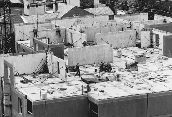
Figure 15.29 Exterior loadbearing wall panels are often made of specially colored concrete, with surface textures cast in. (Courtesy of Blakeslee Prestress, Inc.)
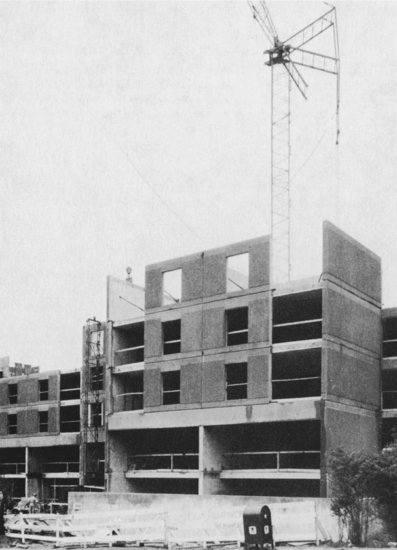
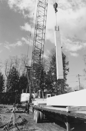
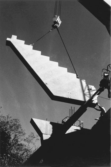
Figure 15.30 A crane hoists a single-piece precast stair for a high-rise building of loadbearing precast concrete wall panels. (Courtesy of Blakeslee Prestress, Inc.)
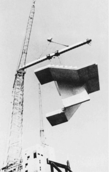
Figure 15.31 A close-up of the precast concrete building frame shown in Figure 15.32. Precast concrete columns with corbels support inverted L- and T-shaped beams. The floor structure is double tees. On the left-hand column, patches where lifting loops were burned off are can be seen. On the right-hand column, lifting loops are on one of the three faces of the column not visible in this photograph.
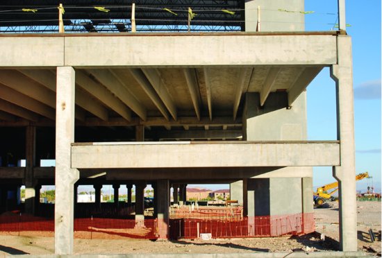
Figure 15.32 A precast concrete building frame with a long-span OWSJ roof structure. Details of the framing are shown in Figure 15.31.
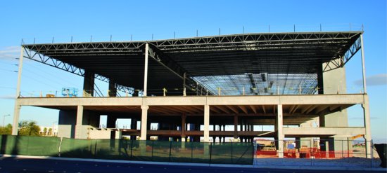
Figure 15.33 Placing a hollow-core slab deck on a precast frame. (Courtesy of Blakeslee Prestress, Inc.)
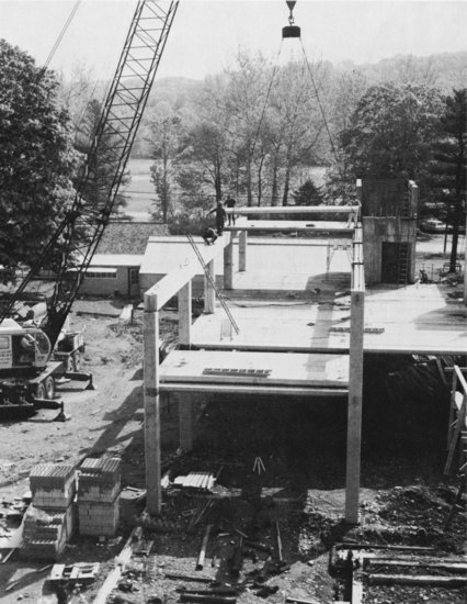
Figure 15.34 (a) A crane lifts a column section from a flatbed truck to begin erection of a tennis stadium in New Haven, Connecticut. (b) Grouted sleeve connectors of the type shown in Figure 15.15 were used to join the precast sections of the bents that support the grandstand seating. (c) Stepped sections of grandstand floor await lifting. (d ) A precast stair section is placed. (e) Precast hollow-core planks will be used for miscellaneous areas of floor. (f ) The relationship of the stairs, bents, and stepped floor sections is evident in this photograph of the finished stadium. (g) The stadium in use, after a construction process that took only 11 months. Seating capacity is 15,000. (Structural engineer: Spiegel Zamecnik & Shah, Inc. Photos by Clark Broadbent. Compliments of Blakeslee Prestress, Inc., P.O. Box 510, Branford, CT 06405; Tel: 203 481 5306.)
(a)
(b)
(c)
(d)

(e)
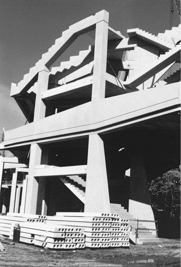
(f)
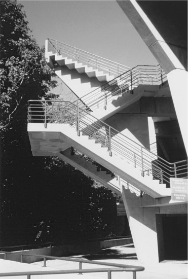
(g)
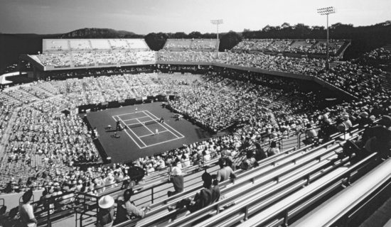
Figure 15.35 A low-rise office building in Texas shows a carefully detailed frame of precast concrete. (Architects: Omniplan Architects. Courtesy of Precast/Prestressed Concrete Institute.)
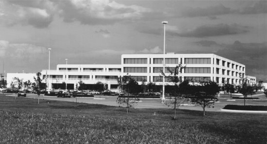
Figure 15.36 Precast concrete girders span the roof of a paper mill in British Columbia. (Engineer: Swan Wooster Engineering Co., Ltd. Courtesy of Precast/Prestressed Concrete Institute.)
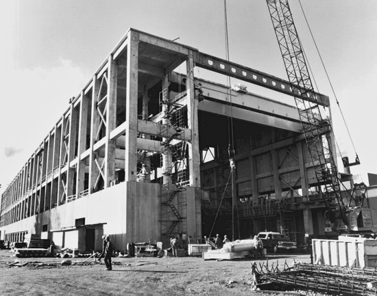
Figure 15.37 The precast walls and slabs of these condominium apartments were erected during the winter in the New Mexico mountains. (Architect: Antoine Predock. Courtesy of Precast/Prestressed Concrete Institute.)
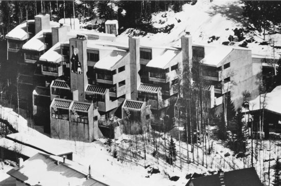
Figure 15.38 Highly customized precast concrete framing is used in this courthouse by architect Eduardo Catalano. (Photo by Gordon H. Schenk, Jr. Courtesy of the architect.)
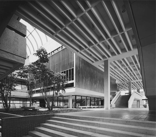
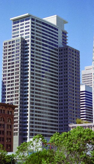
Figure 15.39 The 39 stories of the Paramount Building rise 420 feet (128 m) on a precast concrete frame. The building is located in San Francisco, California, in the zone of highest seismic risk in the United States. Beam–column connections are posttensioned to resist seismic forces. The precast concrete cladding panels act to resist lateral forces on the building. (Architects: Elkus Manfredi and Kwan Henmi. Structural engineers: Robert Engelkirk Consulting Engineers, Inc. Photograph © Bernard André.)
KEY TERMS
REVIEW QUESTIONS
1. Under what circumstances might a designer choose a precast concrete framing system over a sitecast system? Under what circumstances might a sitecast system be favored?
2. Why are precast concrete structural elements usually cured with steam?
3. Explain several methods of producing hollow-core slabs.
4. Diagram from memory several different ways of connecting precast concrete beams to columns.
5. Diagram from memory a method of connecting a pair of untopped double-tee slabs to an inverted-tee beam. Then work out a similar way of connecting a double tee to an L-shaped beam, as would occur around the perimeter of the same building.
6. Explain the construction process for a filigree precast concrete system. What are the unique advantages of this system over other concrete systems?
EXERCISES
1. Design a simple two-story rectangular warehouse, 90 by 180 feet (27 by 54 m), using precast concrete for the floor and roof structure and for the walls as well. Use the preliminary structural design information given in this chapter to help determine the column spacing, the types of elements to use, and the depths of the elements. Draw a framing plan and typical connections for the building.
2. Locate a concrete precasting plant in your area and arrange a visit to view the production process. If possible, arrive at the plant early in the morning, when the strands are being cut and the elements are being lifted from the molds.
3. Learn from the management of the precasting plant where a precast concrete building is being erected; then visit the building site. Trace a typical precast concrete structural element from raw materials through precasting, transporting, and erecting. Are there ways in which this process could be made more efficient? Sketch a few of the typical connections being used in the project.
SELECTED REFERENCES
Precast/Prestressed Concrete Institute. Architectural Precast Concrete (3rd ed.). Chicago, Author, 2007.
This design manual provides technical and design guidelines for achieving high-quality architectural finishes in precast concrete, and includes hundreds of images and line drawings.
Precast/Prestressed Concrete Institute. Design and Typical Details of Connections for Precast and Prestressed Concrete (2nd ed.). Chicago, Author, 1988.
This engineering design manual includes a large collection of drawings of standard connection details.
Precast/Prestressed Concrete Institute. Erector's Manual: Standards and Guidelines for the Erection of Precast Concrete Products. Chicago, Author, 1999.
The 96 pages of this manual describe and illustrate the best ways of hoisting and assembling the elements of a precast concrete building.
Precast/Prestressed Concrete Institute. PCI Design Handbook. Chicago, Author, updated regularly.
This is the major reference handbook for those engaged in designing precast, prestressed concrete buildings. It includes basic building assembly concepts, load tables for standard precast elements, engineering design methods, and a few suggested connection details.
WEB SITES
Precast Concrete Framing Systems
Author's supplementary web site: www.ianosbackfill.com/15_precast_concrete_framing_systems
Altus Group carbon reinforced precast concrete: altusprecast.com
National Precast Concrete Association: precast.org
Precast/Prestressed Concrete Institute (PCI): www.pci.org
Spancrete: www.spancrete.com