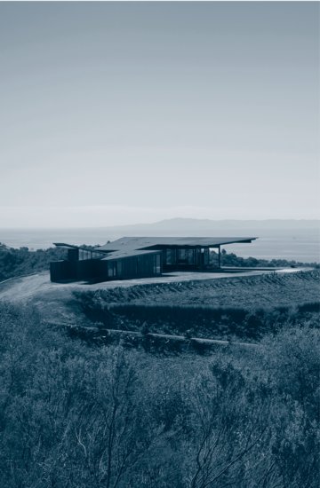
Architect Tom Kundig, of Olson Sundberg Kundig Allen Architects, uses noncombustible, corrugated steel for the roof of a hilltop residence in a fire-prone area of southern California. The simple roof form is lifted above the main living space of the house, shading it from the sun and allowing naturally cool offshore breezes to circulate freely around and through it. (Photograph by Tim Bies, courtesy of Olson Sundberg Kundig Allen Architects.)
16
ROOFING
Structural Panel Metal Roofing
Architectural Sheet Metal Roofing
Roofing and the Building Codes
Figure 16.1 A steep roof can be made waterproof with any of a variety of materials. This thatched roof is being constructed by fastening bundles of reeds to the roof structure in overlapping layers in such a way that only the butts of the reeds are left exposed to the weather.
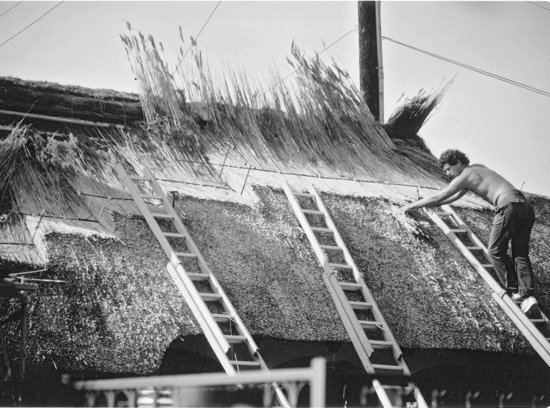
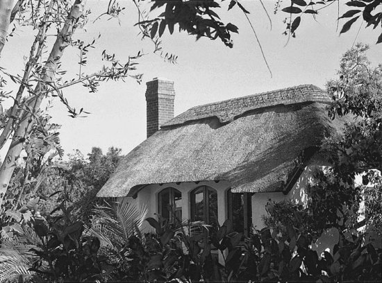
Figure 16.2 The finished thatched roof has gently rounded contours and a pleasing surface texture. The decorative pattern of the ridge cap is the unique signature of the thatcher who made the roof. (Photos of thatched roofs courtesy of Warwick Cottage Enterprises.)
LOW-SLOPE ROOFS
A low-slope roof (often referred to, inaccurately, as a flat roof) is usually defined as one whose slope is less than 2:12, or 17 percent. It is a highly interactive assembly made up of multiple components. The roof deck is the structural surface that supports the roof. Thermal insulation is installed to slow the passage of heat into and out of the building. An air barrier restricts the leakage of air through the roof assembly, and a vapor retarder, used in colder climates or when enclosing humid spaces, prevents moisture vapor from condensing within it. The roof membrane is the impervious sheet of material that keeps water out of the building. Additional layers within the assembly may increase resistance to fire, protect soft insulation boards from damage by foot traffic, or separate replacement roof materials from older, incompatible existing layers. Drainage components, such as roof drains, gutters, and downspouts, remove the water that runs off the membrane. Around the membrane's edges and wherever it is penetrated by pipes, vents, expansion joints, electrical conduits, or roof hatches, special flashings and details must be designed and installed to prevent water penetration.
Roof Decks
Previous chapters of this book have presented the types of structural decks ordinarily used under low-slope roofs: wood panels over wood joists, solid wood decking over heavy timber framing, corrugated steel decking, panels of wood fiber bonded together with portland cement, sitecast concrete slab, and precast concrete slab. The structural deck and its supporting members must be strong and stiff enough to support rain and snow loads, as well as resistant to the forces of wind uplift. The deck itself, or the insulation materials on top of it, must slope steeply enough toward drainage points for water on top of the roof membrane to drain efficiently and reliably. A slope of at least ¼ inch per foot of run (1 in 48, or 2 percent) is normally required by the building code and most manufacturers of low-slope roof membranes. To achieve this, the beams that support the roof deck may be sloped by varying the height of their supporting columns, or the supporting structure may be constructed level and slope created by a layer of thermal insulation of varying thickness installed on the top of the deck. This layer may consist of lightweight insulating concrete or, more frequently, a system of tapered rigid insulation boards.
If a low-slope roof does not drain efficiently, ponding can occur, in which areas of water remain standing for extended periods of time. Except with roof membrane systems specially designed to tolerate standing water, this can cause deterioration of the membrane and increase the chance of leakage. Particularly with long-span roof structures, water accumulation in low spots caused by structural deflections is also a concern. As puddles deepen and increase in weight, the structure may deflect further, progressively attracting more and more water and becoming heavier and heavier. If water cannot drain from these areas and continues to accumulate, overloading and even structural collapse is a possibility.
The roof membrane must be laid over a smooth, continuous surface. A wood deck should have no large gaps, knotholes, or protruding fasteners, or it may be covered with a substrate board to provide a more suitable surface. A sitecast concrete deck should be troweled smooth, and a precast concrete plank deck, if not topped with a concrete fill, must be grouted at junctions between planks to fill the cracks. A corrugated steel deck is usually covered to create a continuous, flat surface. This is done with rigid insulation boards or some variety of substrate board, thin panels of wood fiber or gypsum that are attached to the top surface of the metal deck. Gypsum panel substrate boards are also installed over wood and metal roof decks to increase the fire resistance of the roof assembly.
It is important that the deck be dry at the time roofing operations commence, to avoid later problems with water trapped under the roof membrane. A deck should not be roofed when rain, snow, or frost is present in or on the deck material. Concrete decks and insulating fills must be cured and adequately dried.
If a deck is large in extent, the roofing system should be provided with enough movement joints to keep expansion and contraction or other movement within the deck from stressing the roof membrane. Where building separation joints occur within a building structure, these joints must carry through the roof membrane system as well (Figure 16.24). Where such joints do not occur or are too far apart to satisfy the requirements of the membrane, area dividers, which are much like building separation joints but do not extend below the surface of the roof deck, may be installed (Figure 16.25).
Thermal Insulation
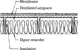
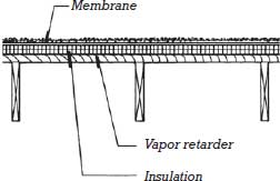
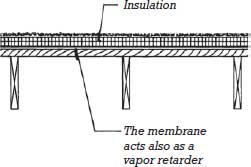
Thermal insulation for a low-slope roof may be installed in any of three positions: below the structural deck, between the deck and the roof membrane, or above the membrane (Figure 16.3).
Figure 16.3 Low-slope roofs with thermal insulation in three different positions, shown here with a wood joist roof deck. At the left, insulation is located below the roof deck. In the center, insulation is placed between the deck and the membrane. At the right, a protected membrane roof is shown with insulation placed above the membrane. Vapor retarders are indicated in the appropriate location for roofs in cold regions. See the accompanying text for a further discussion of the use of vapor retarders in low-slope roof assemblies.
Insulation Below the Roof Deck
Below the roof deck, mineral or glass fiber batts are installed either between framing members or on top of a suspended ceiling assembly. With this type of insulation, the building code normally requires a ventilated airspace between the insulation and the underside of the deck to dissipate water vapor. Below-deck insulation is relatively economical and trouble-free, but it leaves the roof deck and the membrane exposed to the full range of outdoor temperature fluctuations. Where a vapor retarder is required, it is applied on the warm, conditioned side of the roof insulation to control the diffusion of water vapor into the insulated portions of the roof where condensation could occur.
Particularly in residential buildings, spray foam insulation may be applied directly to the underside of the roof deck. When air-impermeable foam insulation with sufficient vapor resistance and insulation value is used, the risk of moisture accumulation within the assembly is minimized, and ventilation between the deck and the insulation is not required. See Chapter 6 for more information about unventilated roof assemblies.
Insulation Between the Roof Deck and the Membrane
The traditional position for low-slope roof insulation is above the roof deck and underneath the membrane. Low-density rigid boards or lightweight concrete that can support the membrane and withstand occasional foot traffic are used. The insulation protects the deck from outdoor temperatures and is itself protected from the weather by the membrane. The roof membrane remains exposed to the exterior environment.
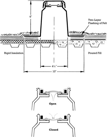
A risk with this insulation strategy is the accumulation of moisture within the insulation. This moisture may come from roof membrane leaks, the leakage of air or diffusion of moisture vapor from within the building, or the roof structural components themselves if they were not sufficiently dry when the roofing system was installed. Moisture trapped within the insulation layers can damage the insulation and roof deck, as well as cause blistering and rupture of the roof membrane from high vapor pressure. Where vapor diffusion from the building interior is a concern, a vapor retarder may be installed below the insulation. Ventilation can also be provided under the roof membrane. One way to accomplish this is with the installation of topside vents, one per 1000 square feet (100 m2), that allow water vapor to pass to the exterior (Figures 16.4 and 16.5). Ventilated low-slope roof assemblies are most effective with roof membranes that are not fully adhered to the layers below, as this allows entrapped moisture to more easily find its way toward the vents from any location under the membrane.
Figure 16.4 Topside roof vents are being installed in this built-up roof membrane to release vapor pressure that may accumulate beneath it. (Courtesy of Manville Corp. FP-10 One Way® Roof Vent.)
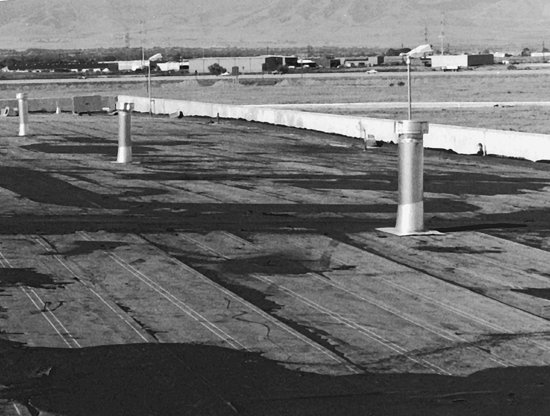
Figure 16.5 This topside roof vent, made of molded plastic with a synthetic rubber valve, allows moisture vapor to escape from beneath the membrane but closes to prevent water or air from entering. (Courtesy of Manville Corp. FP-10 One Way® Roof Vent.)
Insulation Above the Roof Membrane: The Protected Membrane Roof
In a protected membrane roof (PMR) system, insulation is installed above the membrane. This offers two advantages: The membrane is protected from extremes of heat and cold, and the membrane is on the warm side of the insulation, where it is immune to vapor blistering problems. Because the insulation itself is exposed to water when placed above the membrane, it must be made of a material that retains its insulating value when wet and does not decay or disintegrate. Extruded polystyrene foam is the most commonly used insulation type (Figure 16.6). The panels of polystyrene are either embedded in a coat of hot asphalt to adhere them to the membrane below or are laid loose. They are held down and protected from sunlight (which disintegrates polystyrene) by a layer of ballast, which may consist of crushed stone or gravel, or concrete blocks (Figures 16.7 and 16.20). Because the membrane in a PMR system is shielded from sunlight and temperature by the insulation and ballast above, it can be expected to last roughly twice as long as in an assembly where it remains directly exposed to these elements. However, PMR systems do have potential disadvantages. When the roof insulation is exposed to precipitation, it may absorb moisture and lose some of its insulation value. When performing energy calculation for PMR systems, R-values for roof insulation may be slightly reduced from their standard values to account for such losses. PMR systems may not be appropriate for climates with extended periods of rainy, cold weather, as cool water continuously flowing around and under the insulation boards may negate much of their insulating value. Also, repairs to protected membrane roofs, if required, are more costly and time-consuming because accessing the roof membrane requires removal of the layers of material above it.
Figure 16.6 Installing extruded polystyrene foam insulation over a roof membrane to create a protected membrane roof.(Photograph provided by The Dow Chemical Company.)
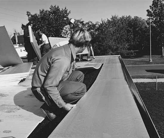
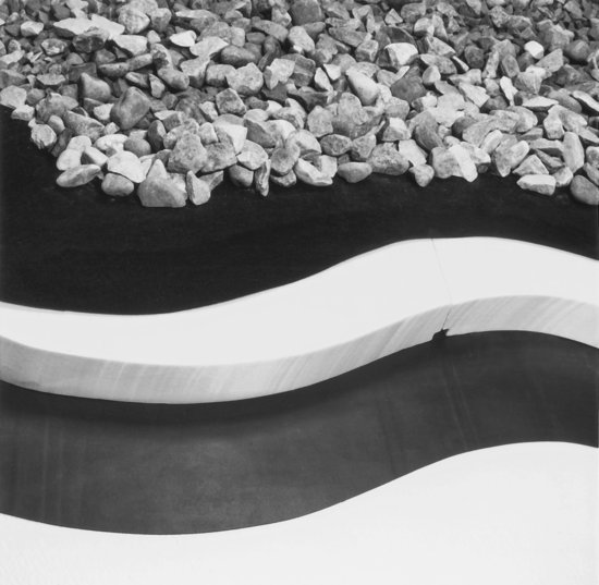
Figure 16.7 A cutaway detail of a protected membrane roof shows, from bottom to top, the roof deck, the membrane, polystyrene foam insulation, a polymeric fabric that separates the ballast from the insulation, and the ballast. (Photograph provided by The Dow Chemical Company.)
Because the roof membrane is located on the warm side of the roof insulation, a separate vapor retarder is not required in a protected membrane roof.
Vapor Retarders and Air Barriers in Low-Slope Roofs
Figure 16.3 shows typical locations for vapor retarders in low-slope roof assemblies. As discussed at greater length in the accompanying sidebar, the need for vapor retarders generally increases with colder climates and higher-humidity interior conditions. However, a consideration unique to low-slope roofing assemblies is the roofing membrane itself, which also has a low vapor permeance and can act as a vapor retarder. If an additional vapor retarder is included in the assembly, there is the possibility of entrapping moisture between these two impermeable layers. This complication makes the decision whether to include a separate vapor retarder in a low-slope roof more dependent on the case-by-case analysis of individual roofing installations rather than simple, generalized criteria.
The traditional material for a vapor retarder consists of two layers of asphalt-saturated roofing felt bonded together and adhered to the upper side of the roof deck with hot asphalt. Vapor retarder sheets made from factory-manufactured self-adhering bituminous membranes are also common, particularly with single-ply roofing systems or where roofing installation methods do not rely on hot asphalt.
A membrane or coating fully adhered to the structural roof deck is the simplest way to achieve an effective air barrier in a low-slope roofing system. The structural deck provides a continuous surface with a minimum of penetrations. By fully adhering the air barrier material to this surface, the chance for leaking air to travel under or around the membrane is minimized. When a vapor retarder is included in the roof assembly, the air barrier membrane and vapor retarder frequently are the same material. When an added vapor retarder is not desired, a vapor-permeable air barrier material may be used. The roof membrane itself can also act as the air barrier in the roof system, particularly when fully adhered to the materials below.
With any type of air barrier membrane, special attention must be given to the interface between the roof edges and the exterior walls. This is the most difficult location to maintain air barrier continuity and the most frequent location of air leakage. For a fuller discussion of air barrier systems, see Chapter 19.
- The temperature and humidity conditions to which a building assembly is exposed over time are not static. A wall system designed exclusively for winter heating conditions may perform poorly when vapor migrates from the exterior inward during summer months with air conditioning in operation. Solar heating of a rain-soaked exterior cladding system can cause strong inward water vapor movement at any time of the year.
- Building assemblies must be able to dry out when wet. Water introduced into a building assembly, such as from penetrating rain or from construction with wet building materials, must have a means to escape so that the assembly can dry.
- Air barriers are also important to the control of water vapor. Under many circumstances, air leakage can transport many times greater amounts of water vapor into an assembly than can vapor diffusion. Air barriers are discussed in Chapter 19.
- Design for water vapor control should consider all components of an assembly. The permeability of exterior sheathing, cladding or roofing, provisions for ventilation, and the location and types of insulating materials within an assembly can all influence the choice and placement of vapor retarders.
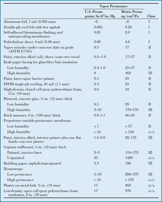
Figure B Vapor permeance of common building materials. Values are typical, and may vary between products from different manufacturers. Class designations are according to IBC criteria, as explained in the accompanying text.
Rigid Insulating Materials for Low-Slope Roofs
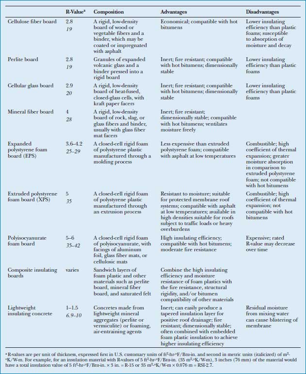
An insulating material for low-slope roofs should have high thermal resistance; adequate resistance to compression, denting, gouging, moisture decay, and fire; and, if part of a hot-applied system, resistance to melting or dissolving when hot asphalt is mopped onto it. No single material has all these virtues. Some rigid insulating materials commonly used on low-slope roofs in North America are listed in Figure 16.8, along with a summary of their advantages and disadvantages. The best choice is often a combination of materials, or a composite board that combines two or more materials into one product, to exploit the best qualities of each. A composite insulating board for installation under a built-up bituminous roof membrane might include, for example, a bottom layer of polyisocyanurate foam with high insulating value and a top layer of perlitic board resistant to hot bitumens.
Figure 16.8 A comparative summary of some rigid insulating materials for low-slope roofs. You can download a PDF of this figure at http://www.wiley.com/go/aflblce6ne.
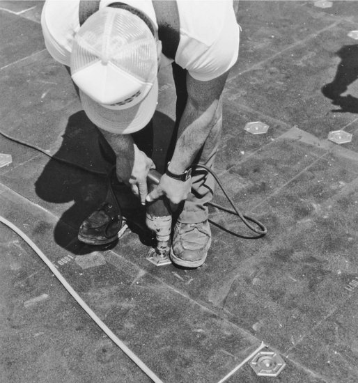
If rigid insulating boards are located below the roof membrane, they may be adhered to the deck with hot asphalt or other adhesives, or fastened to the deck mechanically with screws. Insurance companies favor the mechanical fasteners because they are more secure against wind uplift (Figures 16.9 and 16.10).
Figure 16.9 Workers bed rigid insulation boards in strips of hot asphalt over a corrugated metal roof deck. (Courtesy of GAF Corporation.)
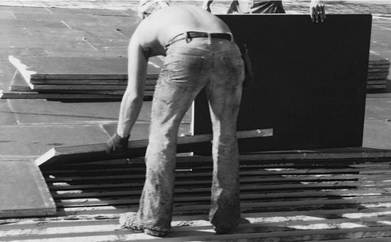
Figure 16.10 Screws and large sheet metal washers attach insulation more securely to a metal deck than can hot asphalt. (Courtesy of GAF Corporation.)
Lightweight insulating concrete is an economical insulating material that also creates a nailable roof deck. Formulated with lightweight aggregates or foaming, air-entraining agents, this material has densities ranging from 20 to 40 lb/ft3 (320 to 640 kg/m3) compared to 145 lb/ft3 (2320 kg/m3) for conventional concrete. Lightweight concrete may be applied directly to corrugated steel decking or over rough concrete decks and can easily be tapered during installation to slope toward points of roof drainage. Thermal resistance per inch is not as high for this material as for most other types of roof insulation. However, plastic foam boards may be embedded in the insulating concrete to achieve higher insulating values within reasonable thicknesses. Lightweight concrete fill insulation contains large amounts of free water at the time it is placed. It must be cured and dried as thoroughly as possible before being covered by the roof membrane, and some form of venting to allow the escape of moisture vapor from the insulation during the life of the roof, via either topside vents or bottomside slotted vented metal decking, is usually advisable. Poured-in-place gypsum, another decking material popular in the past for forming lightweight, nailable sloping roof decks, is no longer used in new construction.
An insulation coverboard made of materials similar to those described for substrate boards may be placed over the rigid insulation prior to installation of the roof membrane. The coverboard protects the insulation from damage by foot traffic on the finished roof, increases the fire resistance of the roof assembly, and separates the membrane from incompatible insulation materials. Thin, synthetic fabrics may also be used for similar purposes.
Membranes for Low-Slope Roofs
Membranes for low-slope roofing can have life expectancies ranging from 10 to 30 years, depending on the membrane material and thickness, its exposure to extremes of temperature and UV radiation, and the quality of the roof's installation and maintenance. These membranes fall into three categories: bituminous roof, single-ply, and fluid-applied.
Bituminous Roof Membranes
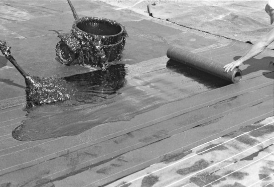
Bituminous roof membranes are of two types, built-up or modified bitumen. A built-up roof (BUR) membrane is assembled in place from multiple layers of asphalt-impregnated roofing felt bedded in layers of hot bitumen (Figures 16.11, 16.12, and 16.13). The felt, made from cellulose, glass, or synthetic fibers, is saturated with asphalt at the factory and delivered to the site in rolls. The hot bitumen applied in the field is usually asphalt derived from the distillation of petroleum. But for dead-level or very low-slope roofs, coal tar pitch is used instead because of its greater resistance to standing water. Polymer-modified asphalts, as described later for modified bitumen roofs, may also be used. The felts are laminated in overlapping layers (plies), with the hot bitumen welding them into a unified membrane, two to four plies thick. The more plies used, the more durable the roof.
Figure 16.11 Two built-up roof constructions, as seen from above. The top diagram is a cutaway view of a protected membrane roof over a sitecast concrete roof deck. The membrane is made from plies of felt overlapped in such a way that at no location is it less than four plies thick. Rigid foam insulation boards are bedded in hot asphalt over the membrane and ballasted with stone aggregate to keep them in place and protect them from sunlight. The bottom diagram shows rigid insulation boards attached to a corrugated steel roof deck in two staggered layers to provide a firm, smooth base for application of the membrane. A three-ply membrane is shown. In cold climates, a vapor retarder may be installed between the layers of insulation or under the insulation over a substrate board fastened to the steel deck.
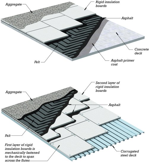
Figure 16.12 A base sheet of asphalt-saturated felt is installed over rigid insulation, using a machine that unrolls the felt and presses it into a layer of hot asphalt. (Courtesy of The Celotex Corporation.)
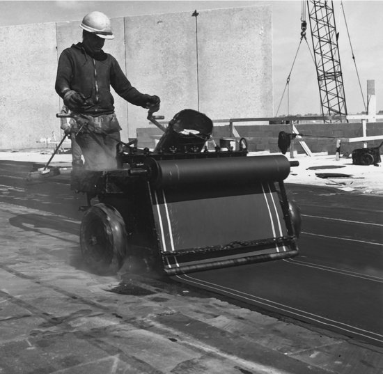
Figure 16.13 Overlapping layers of roofing felt are hot-mopped with asphalt to create a four-ply membrane. (Courtesy of Manville Corporation.)
To protect the membrane from sunlight and physical wear, a layer of crushed stone or other mineral granules is embedded in the top surface. Less commonly, a built-up roof may be made from felt plies bedded in cold-applied mastics (solvent-based asphalts). These are asphalt compounds applied by spray or brush at ambient temperatures and then cured through solvent evaporation.
A modified bitumen roof membrane is made from factory-manufactured sheets of polymer-modified bitumens. Modified bitumens are asphalt materials to which compounds such as atactic polypropylene (APP) or styrene-butadiene-styrene (SBS) have been added to increase the material's flexibility, cohesion, toughness, and resistance to flow. Modified bitumen roof membrane sheets are also reinforced with plastic or glass fibers or fibrous mats. Sheet thickness typically ranges from 0.040 to 0.160 inch (1.0–4.0 mm).
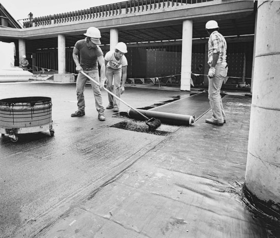
Like a built-up roof, modified bitumen sheets are assembled in place in overlapping layers to form a multi-ply system, usually two or three plies thick. The sheets are bonded to one another in a number of possible ways: With a torch-applied membrane, as a roofing sheet is unrolled, an open-flame apparatus is used to thermally fuse the underside of the sheet to the top surface of the substrate or underlying sheet. A hot-mopped membrane relies on the application of hot asphalt to bond the sheets, a cold process or cold-applied adhesive membrane uses liquid adhesives, and a self-adhered membrane relies on factory-applied adhesives (Figure 16.14).
Figure 16.14 Roofers bond a polymer-modified bitumen membrane to a concrete deck with a cold-applied adhesive. The seams will be heat-fused together. (Courtesy of Koppers Company, Inc.)
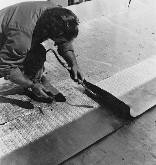
The top or cap sheet in a modified bitumen roof is surfaced with mineral granules, thin metallic laminates, or asphaltic or elastomeric coatings for greater resistance to ultraviolet deterioration, wear, and fire (Figure 16.15). Cap sheets with reflective white coatings that comply with cool roof standards are also available. In comparison to built-up roofs, modified bitumen roofs combine the toughness and redundancy of multi-ply field application with the improved material qualities of factory-manufactured sheets. Built-up and modified bitumen systems may also be combined, with a modified bitumen cap sheet applied over several plies of built-up roofing to create a hybrid membrane bituminous roof. Bituminous roofing systems account for approximately 40 percent of the market for low-slope roofing membranes, with the larger portion of this share belonging to modified bitumen systems.
Figure 16.15 A roofer heat-fuses a seam between two sheets of an aluminum-faced modified bitumen membrane. The aluminum foil protects the membrane from the sun and reflects solar heat from the roof. (Courtesy of Koppers Company, Inc.)
Single-Ply Roof Membranes
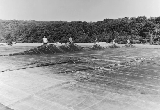
Single-ply roof membranes are a diverse and seemingly ever-evolving group of sheet materials that are applied to the roof in a single layer (Figure 16.16). Compared to bituminous roof membranes, they require less on-site labor, and especially in comparison to built-up roof membranes, they are more elastic and therefore less prone to cracking or tearing as they age. However, single-ply membranes lack the redundancy of bituminous membranes, making them potentially more vulnerable to leakage through small holes or seaming defects. Common membrane thicknesses vary from 0.035 to 0.120 inch (0.9 to 3.0 mm), depending on the membrane material type and the requirements of the roofing application. The membrane sheets come in rolls in standard widths ranging from 3 to 20 feet (0.9 to 6 m). They are affixed to the roof deck by adhesives, the weight of ballast, or fasteners concealed in the seams between sheets (Figure 16.17).
Figure 16.16 Workers unfold a wide single-ply, EPDM roof membrane sheet. Using wider sheets when roofing larger areas reduces the amount of field seaming work required. (Photo courtesy of Carlisle SynTec Systems.)
The materials used for single-ply membranes fall into two groups: thermoplastic and thermosetting. Thermoplastic materials can be softened by the application of heat and may be joined at the seams by heat (or solvent) welding. This welding process, which fully fuses one sheet to another, results in seams between sheets that are as strong and permanent as the sheets themselves (Figures 16.17, 16.18, and 16.19). Thermosetting materials, also sometimes referred to as elastomerics, have a more tightly linked molecular structure and cannot be softened by heat. Thermosetting sheets are joined at the seams by liquid adhesives or pressure-sensitive tapes. Single-ply membranes, unlike multi-ply bituminous membranes, have no redundancy.
Figure 16.17 A thermoplastic membrane is attached with closely spaced fasteners along its edge. The screws are long enough to reach the wooden deck beneath the insulation layers. Oversized washers keep the membrane from tearing when subjected to wind uplift forces. (Photo by Joseph Iano.)
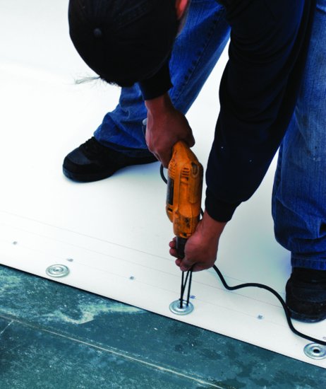
Figure 16.18 After the first sheet of membrane is fastened in place, the next sheet is unrolled alongside so that it overlaps the edge fasteners in the first sheet. After the seam is welded, water running on the surface of the membrane cannot reach the fastener penetrations. The surface under the roofing membrane is a gypsum insulation coverboard. (Photo by Joseph Iano.)
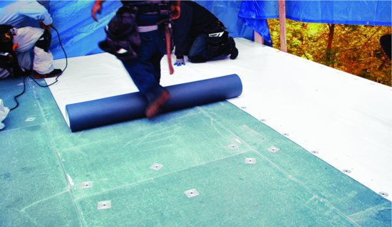
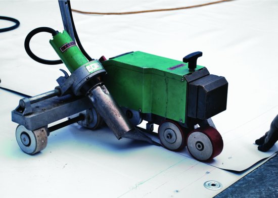
Figure 16.19 A hot-air welder used to weld the seams in a thermoplastic membrane. The machine delivers air at the proper temperature and travels along the seam at the prescribed rate to maintain the quality of the weld. (Photo by Joseph Iano.)
The most commonly used thermoplastic roof membrane materials are polyvinyl chloride (PVC) and thermoplastic polyolefin (TPO). PVC roof membranes, made of PVC resins, plasticizers, stabilizers, and reinforcing fibers or fabrics, have a track record of successful performance established over many decades. However, concerns over toxic chemicals associated with the manufacture and formulation of PVC have led to questions regarding the appropriateness of PVC for use in buildings. Although PVC manufacturers continue to improve their manufacturing processes and institute materials recycling programs in response to public concerns, segments of the construction industry have moved toward avoidance of this material in building products. TPO roof membranes are somewhat newer to the North American roofing market. They are made from blends of polyethylene, polypropylene, and ethylene-propylene rubber polymers reinforced with fibers or fabrics. TPO membranes exhibit good resistance to heat and ultraviolet (UV) radiation, characteristics more commonly associated with thermosetting membranes, but as thermoplastics, their seams can be heat welded. PVC and TPO together account for approximately 20 percent of the market for low-slope roofing materials. Other, less widely used thermoplastic roof membrane materials include ketone ethylene ester (KEE) and a class of materials referred to as PVC alloys or PVC compounded thermoplastics, made from various blends of PVC and other polymers. Thermoplastic roof membranes are generally available in a broad range of colors, including reflective white for cool roofs.
The most commonly installed thermosetting roof membrane material is ethylene propylene diene monomer (EPDM), a synthetic rubber that may or may not include fiber or fabric reinforcing. EPDM has a stable chemical structure with excellent resistance to ozone, heat, UV radiation, and weathering. It is most commonly black, but is also available in cool white from some manufacturers. Because EPDM cannot be heat welded, seaming is performed with tapes or adhesives. Like PVC, EPDM has a many-decades-long track record of successful performance. It is the most widely used material in North America for low-slope roofing of any type, accounting on its own for more than one-third of the market for such applications. Other thermosetting roof membrane materials include chlorosulfonated polyethylene (CSPE) and polyisobutylene (PIB).
Fluid-Applied Roof Membranes
Fluid-applied roof membranes are frequently used for domes, shells, and other complex shapes that are difficult to roof by other means. Such shapes are often too flat on top for shingles but too steep on the sides for built-up roof membranes; if doubly curved, they are difficult to cover with preformed sheets. Fluid-applied membranes are installed with a roller or spray gun, usually in several coats, and cure to form a solid membrane. Materials applied by this method include neoprene (with a protective layer of CSPE), silicone, polyurethane, butyl rubber, asphalt emulsion, and polymethyl methacrylate (PMMA).
Fluid-applied membranes are also used as a waterproofing layer over sprayed-on polyurethane foam insulation in proprietary roofing systems designed for surfaces that are hard to fit with flat sheets of insulation and membrane. These systems are also a convenient means for adding thermal insulation and a new roof membrane over existing but deteriorated built-up roofs on any shape of building.
Ballasting and Traffic Decks
Roof membranes may be covered after installation with a ballast of loose, rounded stone aggregate ranging in size from 1½ to 2½ inches (38 to 64 mm) in diameter or with precast concrete paver blocks. The ballast holds the membrane down against wind uplift and protects the membrane from ultraviolet light and physical wear. It may also contribute to the fire resistance of the roof covering.
Traffic decks are installed over flat roof membranes for walks, roof terraces, and sometimes driveways or parking surfaces. Two different systems are used: In one, plastic pedestals are placed on top of the roof membrane to support the corners of square paving stones or slabs with open joints (Figure 16.20). In the other, a drainage layer of gravel or pervious concrete is leveled over the membrane, and open-jointed paving blocks are installed on top. In either detail, water falls through the joints in the paving and is caught and drained away by the membrane below. Notice that the membrane is not pierced in either system. To protect the membrane from accidental damage, a protective layer made of roof membrane or other material is frequently placed over the membrane before the traffic deck components are installed.
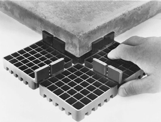
Figure 16.20 Plastic pedestals support stone or precast concrete paving blocks over a low-slope roof membrane, permitting the use of a low-slope roof as an outdoor terrace. Each high-density polyethylene pedestal supports the adjacent corners of four paving blocks. The vertical fins on the pedestal provide a uniform drainage space between the blocks. Matching polyethylene leveling plates (not shown) can be placed under the pedestals to compensate for irregularities in the roof surface. Adjustable-height pedestals that rely on threaded, telescoping sections are also available. (Photo courtesy of Envirospec, Inc., Buffalo, NY.)
Edge and Drainage Details
Some typical details of low-slope roofs are presented in Figures 16.21 through 16.30. All are shown with built-up roof membranes. Details for single-ply membranes are similar, though the membranes themselves are only one-ply in thickness.
Figure 16.21 A roof edge for a conventional built-up roof. The membrane consists of four plies of felt bedded in asphalt with aggregate surfacing. The base flashing is composed of two additional plies of felt that seal the edge of the membrane and reinforce it where it bends over the curb. The curb directs water toward interior drains or scuppers rather than allowing it to spill over the edge. The exposed vertical face of the metal roof edge is called a fascia.
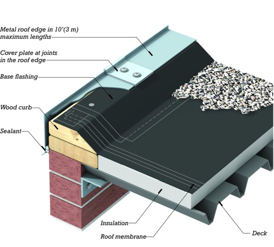
Figure 16.22 A roof edge system for low-slope roofs. The perforated metal strip is fastened to the roof with a mastic adhesive that oozes through the perforations to create a tighter bond. When the adhesive has hardened, a galvanized steel curb is fastened in place with the tabs of perforated metal and an aluminum roof edge is hooked on, with a backup piece at the end joints as shown to prevent leakage. Lastly, the roof edge and the membrane are locked in place simultaneously by installing a clamping strip that engages the hook on the top of the aluminum roof edge. The clamping strip is held in place by screws that pass through the edge of the membrane into the galvanized curb, as seen at the top of the photograph. (Product of W. P. Hickman Company, Asheville, NC, USA.)
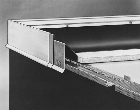
Figure 16.23 Detail of a scupper. The curb is discontinued to allow water to spill off the roof into a gutter and downspout. Additional layers of felt, called stripping, seal around the sheet metal components. Most roofs use interior drains (Figure 16.29) as their primary means of drainage, with scuppers more frequently used as secondary drainage to limit ponding in the case of a clog in the primary drain.
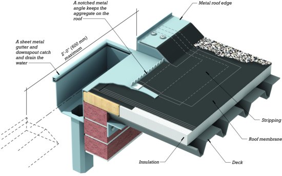
Figure 16.24 A building separation joint in a low-slope roof. Large differential movements between the adjoining parts of the structure can be tolerated with this type of joint because of the ability of the flexible joint cover to adjust to movement without tearing. High curbs keep standing water away from the edge of the membrane, which is sealed with a two-ply base flashing.
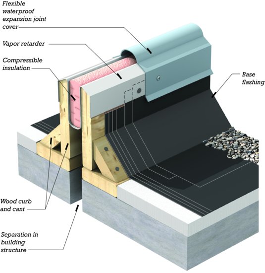
Figure 16.25 An area divider is designed to allow for some movement only in the membrane itself, not in the entire structure. It is used to subdivide a very large membrane to allow for thermal movement.
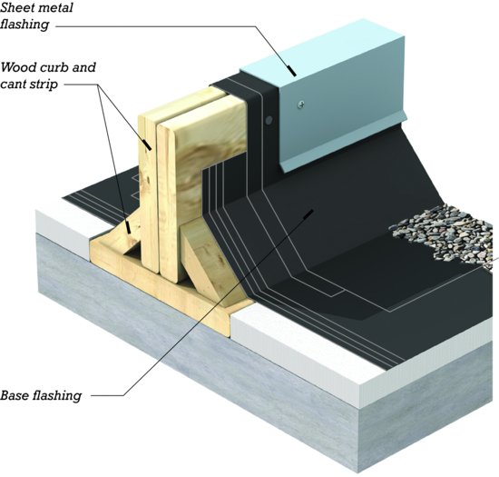
Figure 16.26 A parapet—a low wall that projects above the roof edge—with conventional counterflashing and coping. Cant strips, as seen in this and many other illustrated details in this chapter where the roof membrane turns up onto a vertical surface, are commonly used with bituminous roofing, in which the less flexible membranes and multiple plies cannot easily make sharp right-angle bends. Single-ply membranes usually do not require cant strips at similar conditions.

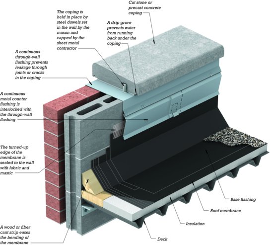
Figure 16.27 A parapet coping system. The perforated metal channel is fastened to the masonry with a mastic adhesive or mechanical fasteners. Sections of metal coping are snapped over the channel, with a special pan element beneath the joints to drain leakage. (Product of W. P. Hickman Company, Asheville, NC, USA.)
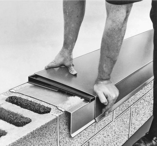
Figure 16.28 A conventional cast iron interior roof drain for a low-slope roof. Two plies of felt stripping seal around the sheet metal flashing.
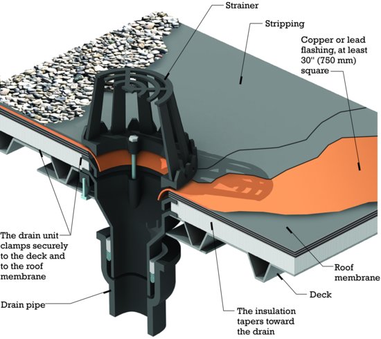
Figure 16.29 A proprietary single-piece roof drain made of molded plastic. (Product of W. P. Hickman Company, Asheville, NC, USA.)
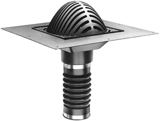
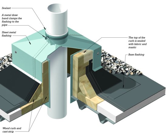
Figure 16.30 A roof penetration for a plumbing vent stack. Notice how this and all the previous edge and penetration details for a flat roof use the curb, cant strip, and stripping to keep standing water away from the edges of the membrane.
Structural Panel Metal Roofing
Manufacturers of prefabricated metal building systems have developed proprietary systems of metal roofing panels that can be used as low-slope roofs at pitches as shallow as ¼:12 (1 in 48, or 2 percent). These systems can be applied not only to prefabricated metal buildings but to buildings constructed of other materials as well (Figures 16.31, 16.32, and 16.33). They are called structural panel metal roofing because the folded shape of the metal roofing gives it sufficient stiffness to support itself and normal rain and snow loads between purlins without the need for a supporting deck beneath. This name also distinguishes it from architectural sheet metal roofing, the traditional forms of metal roofing that are not self-supporting. Architectural sheet metal roofing is utilized largely on steep roofs and is described later in this chapter.
Figure 16.31 As a first step in reroofing a building with a structural metal roof, steel Z-purlins are erected over the old roof on tubular metal posts. (Courtesy of Metal Building Manufacturers Association.)
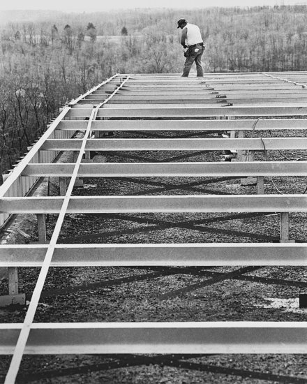
Figure 16.32 A proprietary metal clip is used to fasten the metal roofing sheets to the Z-purlins while allowing for thermal movement in the sheets. The plastic foam collar avoids thermal bridging. (Courtesy of Metal Building Manufacturers Association.)
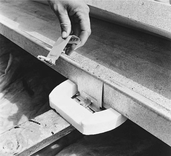
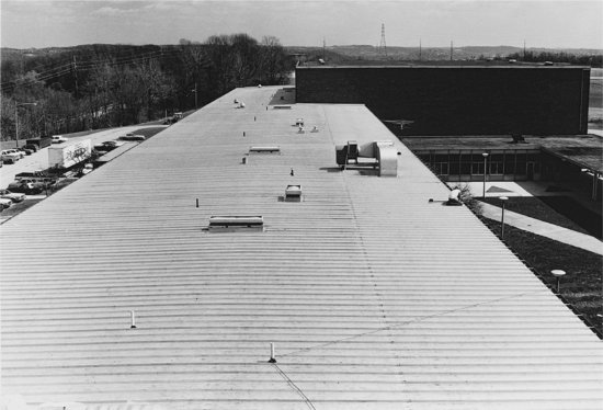
Figure 16.33 The completed structural metal roof has a slope of only ¼:12 (1:48). The numerous penetrations for plumbing vents, air vents, and ductwork are typical of low-slope roofs. (Courtesy of Metal Building Manufacturers Association.)
STEEP ROOFS
Roofs with a pitch of 2:12 (17 percent) or greater are referred to as steep roofs. Traditional thatch, occasionally still used for the restoration of historic structures, is an attractive and effective, but highly labor-intensive, roofing material consisting of bundles of reeds, grasses, or leaves (Figures 16.1 and 16.2). Modern steep-slope shingle and sheet metal roofs of many types are common to every type of building and range from the most economical roof coverings to the most durable and costly.
Insulation and vapor retarders for steep roofs are most often installed below the roof sheathing. Alternatively, the underside of the roof deck may be left exposed in the finished construction, with a vapor retarder and rigid insulation boards installed above. In this second scenario, a nailable surface for the finish roofing is provided by fastening a layer of plywood or OSB over the insulation boards as a nail base for the roofing, or a composite insulation board with a nailable panel factory-bonded to the rigid insulation may be used. Examples of both of these approaches to steep-slope roofing are illustrated in Chapters 6 and 7.
In cold climates, steep roofs may have a tendency to form ice dams at the eaves under wintertime conditions. Where the risk of ice damming is high, building codes require rubberized underlayment or other ice barrier material along the eaves to prevent trapped water from entering the building (see Chapter 6).
Shingles
The word shingle is used here in a generic sense to include wood shingles and shakes, asphalt shingles, slates, clay tiles, and concrete tiles. What these materials have in common is that they are applied to the roof in small, overlapping units with staggered vertical joints.
Wood shingles are thin, tapered slabs of wood sawn from short pieces of tree trunk with the grain of the wood running approximately parallel to the face of the shingle (Figure 16.58). Wood shakes are thicker than shingles, exhibit a rougher texture, and are frequently split from the wood rather than sawn. Most wood shingles and shakes in North America are made from red cedar, white cedar, or redwood to take advantage of these woods' natural decay resistance.
Traditionally, wood shingles and shakes were installed over skip sheathing (spaced sheathing), spaced boards running perpendicularly across the sloped roof rafters. Skip sheathing allows air flow underneath the shingles that prevents condensation and deterioration of the shingles (Figure 16.34). When applied over continuous, solid sheathing, airflow underneath the wood shingles and shakes can be provided by adding spaced wood strips over the sheathing or with a breather mat, a wiry plastic mat placed under the shingles that creates a thin airspace. Wood roof coverings are moderately expensive and are not highly resistant to fire unless the shakes or shingles have been pressure treated with fire-retardant chemicals. They eventually fail from erosion of the wood fibers and may be expected to last 15 to 25 years under average conditions (Figures 16.35 and 16.36).
Figure 16.34 Wood shingles applied over skip sheathing, as seen from below. Even without a continuous roof sheathing or roofing underlayment, this shingle installation provides reliable protection from the weather. (Photo by Joseph Iano.)
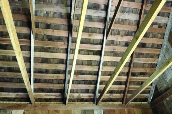
Figure 16.35 Wood shingles and shakes are installed so that any part of the roof is always covered by at least three shingles. Coverage recommendations also vary with the slope of the roof and the quality of the wood used in the shingles or shakes. (Photo by Joseph Iano.)
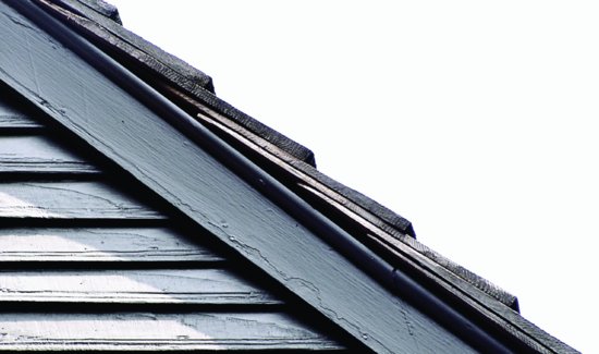
Figure 16.36 Shake installation over a new roof deck. Strips of asphalt-saturated felt have been placed in advance with their lower edges unfastened. Each course of shakes is laid out, slipped up under its felt strip, then quickly fastened with pneumatic powered staplers as the roofers walk across the roof. (Photograph courtesy of Senco Products, Inc.)
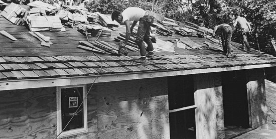
Asphalt or composition shingles are die-cut from heavy sheets of asphalt-impregnated felt faced with mineral granules to act as a wearing layer and decorative finish. Most felts are based on glass fibers, but some still retain the older cellulose composition. The most common type of asphalt shingle, which covers probably 90 percent of the single-family houses in North America, is 12 inches by 36 inches (305 mm by 914 mm) in size. (A metric-size shingle 337 mm by 1000 mm is also widely marketed.) In the most popular pattern, each shingle is slotted twice to produce a roof that looks as though it were made of smaller shingles (Figures 16.37–16.41). Other sizes and many other styles are available, including thicker shingles that are laminated from several layers of material. Asphalt shingles are inexpensive to buy, quick to install, moderately fire resistant, and have a life expectancy of 15 to 25 years, depending on their composition.
Figure 16.37 Installing asphalt shingles. To give a finer visual scale to the roof, the slots make each shingle appear to be three smaller shingles when the roof is finished. Many different patterns of asphalt shingles are available, including ones that do not have slots. (Photo by Edward Allen.)
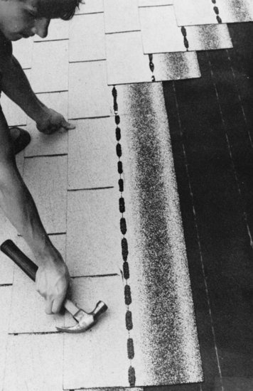
Figure 16.38 Laminated asphalt shingles create a pleasing, textured roof surface. The cupola roof is copper sheet metal with standing seams.
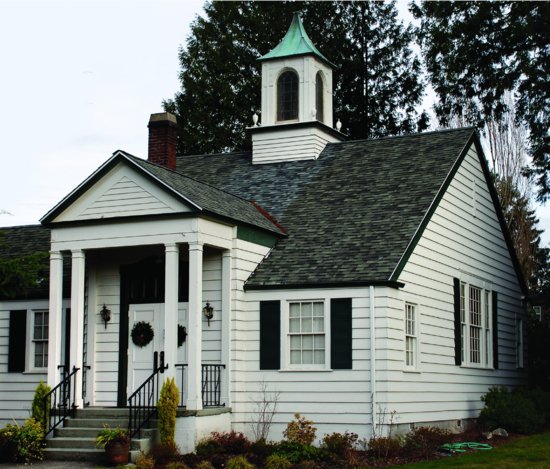
Figure 16.39 Starting an asphalt shingle roof. As explained in Chapter 6, building codes require the installation of an ice barrier beneath the shingles along the eave in regions with cold winters prone to ice damming. Where required, the ice barrier would replace the lowest course of asphalt-saturated felt paper shown in this illustration.
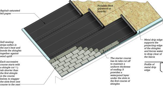
Figure 16.40 Completing an asphalt shingle roof. A metal or plastic ridge vent strip (see Chapter 6) is often substituted for the shingle tabs on the ridge to provide an outlet for ventilation under the roof sheathing.
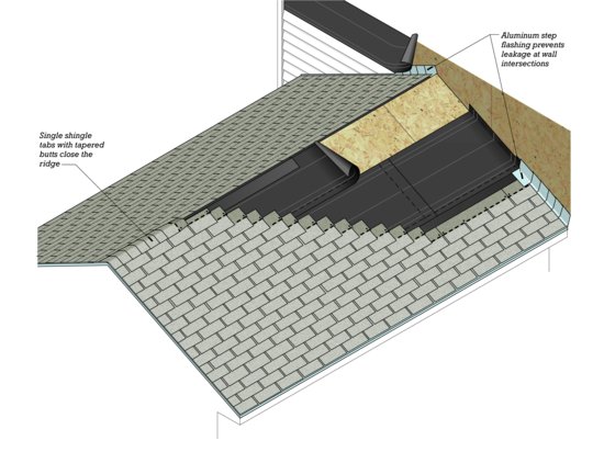
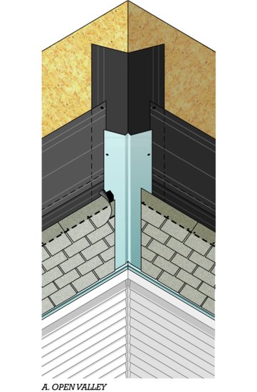
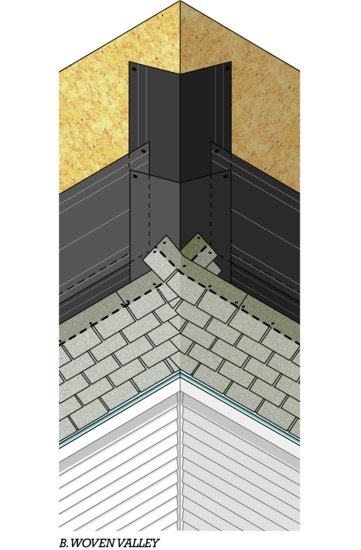
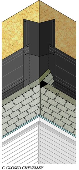
Figure 16.41 A valley is formed in a roof where two sloping roof planes meet above an inside corner of the building. Three alternative methods of making a valley in an asphalt shingle roof are shown here. (a) The open valley uses a sheet metal flashing; the ridge in the middle of the flashing helps prevent water that is coming off one slope from washing up under the shingles on the opposite slope. The woven valley (b) and cut valley (c) are favorites of roofing contractors because they require no sheet metal. The solid black areas on shingles in the open and cut valleys indicate areas to which asphaltic roofing cement is applied to adhere shingles to each other.
The same sheet material from which asphalt shingles are cut is also manufactured in rolls 3 feet (914 mm) wide as asphalt roll roofing. Roll roofing is very inexpensive and is used primarily on utility and agricultural buildings. Its chief drawbacks are that thermal expansion of the roofing or shrinkage of the wood deck can cause unsightly ridges to form in the roofing and that thermal contraction can tear it.
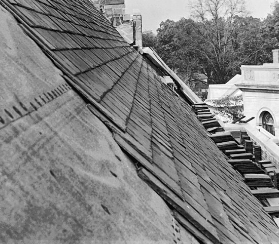
Slate shingles for roofing are delivered to the site split, trimmed to size, and punched or drilled for nailing (Figures 16.42 and 16.43). They form a fire-resistant, long-lasting roof that is suitable for buildings of the highest quality. Its first cost is high, but a slate roof typically lasts 60 to 80 years.
Figure 16.42 Splitting slate for roofing. The thin slates in the background will next be trimmed square and to dimension, after which nail holes will be punched in them. (Photo by Flournoy. Courtesy of Buckingham-Virginia Slate Corporation.)
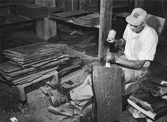
Figure 16.43 A slate roof during installation. (Courtesy of Buckingham-Virginia Slate Corporation.)
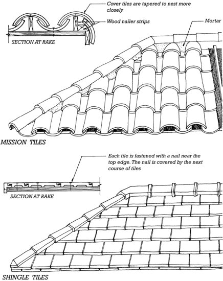
Clay tiles have been used on roofs for thousands of years. It is said that the tapered barrel tiles traditional to the Mediterranean region (similar to the mission tiles in Figure 16.44) were originally formed on the thighs of the tilemakers. Many other patterns of clay tiles are now available, both glazed and unglazed. Concrete tiles are generally less expensive than those of clay and are available in some of the same patterns. Tile roofs are heavy, durable, highly resistant to fire, and relatively expensive in first cost. Expected lifetimes range from 30 to 75 years, depending on climate and the resistance of the tiles to water absorption.
Figure 16.44 Two styles of clay tile roofs. The mission tile has ancient origins.
Other materials used for roof shingles include sheet metal, rubber, fiber-reinforced cement, and plastic. Each type of shingle must be laid on a roof deck that slopes sufficiently to ensure leakproof performance. Minimum slopes for each material are specified by the manufacturer and the building codes. The minimum slope for a standard asphalt shingle roof is usually 4:12 (33 percent); with specially protective underlayments, slopes as low as 2:12 (17 percent) may be acceptable in some circumstances. For any shingle type, slopes greater than the minimum can better resist leakage from water driven up the roof surface by heavy winds.
Architectural Sheet Metal Roofing
Thin sheets of metal have been used for roofing since ancient times and remain a popular roofing material to this day. They are installed using ingenious systems of joining and fastening to maintain watertightness (Figures 16.45–16.50). Seams between sheets must be spaced closely enough to hold the sheets securely against wind uplift and minimize oil canning (unsightly waviness). These seams also create strong visual patterns that can be manipulated by the designer to emphasize the qualities of the roof shape. Architectural sheet metal roofing is relatively high in first cost but, when properly installed, can be expected to last for many decades.
Figure 16.45 A roofer forms standing-seam pans from a coil of copper sheet metal and a portable pan-forming machine mounted in the back of a pickup truck. (Photo by Joseph Iano)
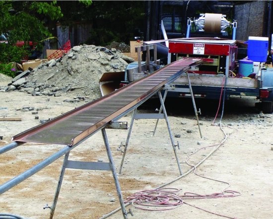
Figure 16.46 Standing-seam copper roofs. (Designer: Emil Hanslin. Courtesy of Copper Development Association, Inc.)
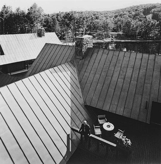
Figure 16.47 An automatic roll seamer, moving under its own power, locks standing seams in a copper roof. A cleat is just visible at the lower right. (Photo courtesy of DBI/SALA, Red Wing, MN; Courtesy of Copper Development Association, Inc.)
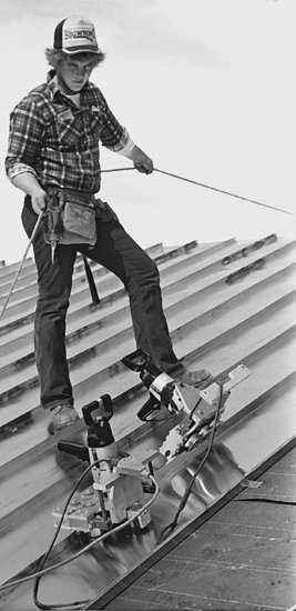
Figure 16.48 Installing a flat-seam metal roof. The three diagrams at the bottom of the illustration show the steps in forming the seam, viewed in cross section. The cleats, which fasten the roofing to the deck, are completely concealed when the roof is finished. To ensure that seams remain watertight, they are sealed with elastomeric sealant. For low slopes, seams may be soldered.
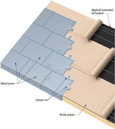
Figure 16.48 (Continued)
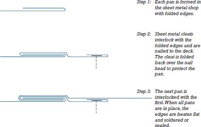
Figure 16.49 Installing an architectural standing-seam metal roof. For low slopes, seams may be made taller or sealed with elastomeric sealant.
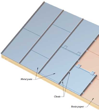
Figure 16.49 (Continued)
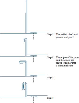
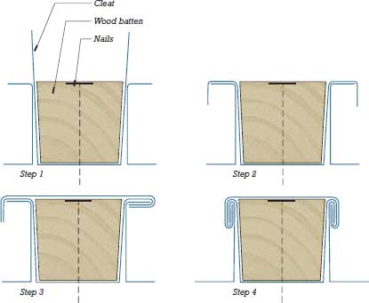
Figure 16.50 Installing a batten-seam metal roof. The battens are tapered in cross section to allow for expansion of the roofing metal. For low slopes, seams may be sealed with elastomeric sealant.
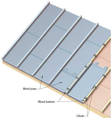
Figure 16.50 (Continued)
Various types of metal may be used in the production of architectural sheet metal roofs:
- Lead is a soft, easily formed, very long-lasting metal that oxidizes over time to a dull white color. It is also toxic to humans and its use in building materials is discouraged by leading green building programs. Where it is used or encountered, special health precautions are required during its handling.
- Copper is a relatively soft metal that turns a beautiful blue-green in clean air and a dignified black in an industrial atmosphere; various chemical treatments can be used to obtain and preserve the desired color.
- Lead-coated copper sheet has historically been used to combine the greater strength of copper with the gray-white color of lead and to avoid the staining of wall materials by oxides of copper that can occur with rainwater runoff from uncoated copper roofs. As noted earlier, the presence of lead in building materials is discouraged by green building programs.
- Zinc metal roofing is a long-lasting roofing metal made of zinc alloyed with small amounts of copper and titanium to improve its workability. It normally ages to a dark gray color and can also be treated in various ways to alter or preserve its appearance.
- Stainless steel and titanium are strong and long-lasting but less easily worked than other roofing metals. Both are silvery-white.
- Zinc-tin alloy coated stainless steel has a darker, duller appearance than uncoated stainless steel. This material is very similar in appearance to—and is sometimes equated with—a lead-tin alloy coated metal called terne-coated stainless steel that is no longer manufactured but may still be found on older buildings.
The metals in the preceding list all form self-protecting oxide coatings (patinas) that provide long-lasting resistance to corrosion. They are usually installed uncoated and allowed to patinate naturally. Other, less expensive metals, which are not as long-lasting in an uncoated condition, are commonly coated at the factory with high-performance organic (paintlike) coatings that extend their life expectancy and provide a wide range of color choice. These include aluminum, metallic-coated steel (steel coated with alloys of zinc or zinc-aluminum), or zinc-tin alloy coated steel, and even, occasionally, plain or ferrous steel without any protective metallic coating. For more about architectural metals, see Chapter 12.
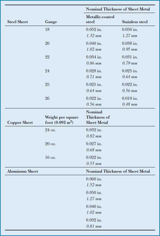
The thickness of steel sheet traditionally has been specified by gauge (also spelled gage), a system of whole numbers in which lower numbers correspond to greater metal thickness. However, due to the absence of uniformity in the translation between gauge and actual metal thickness, sheet metal standards now specify metal thickness in decimal or fractional inches. The exception to this rule is copper, which is specified by weight, expressed in ounces per square foot (0.092 m2). In general, thicker metal sheets are longer-lasting, less prone to distortion, often more difficult to form into shapes, and more expensive than thinner sheets. Figure 16.51 lists typical thicknesses for some common sheet metal roofing materials.
Figure 16.51 Thicknesses of sheet metals commonly used in architectural sheet metal roofing.
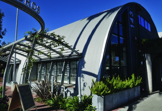
When metal roofing is custom-fabricated by the sheet metal contractor from unformed metal stock, it is specified as sheet metal roofing (Figure 16.45). Alternatively, roofing panels may be factory-formed into families of shapes that can be selected from a catalog. In this case, the roofing is specified as metal roof panels. Factory-made sheet metal roof panels are usually made from aluminum or metallic-coated steel and finished with organic coatings. They may rely on interlocking seams with concealed fastener systems similar in appearance to traditional standing-seam or batten-seam sheet metal roofing (Figure 16.52), or they may consist of simpler corrugated or folded profiles fastened with exposed screws and rubber washers (Figure 16.53). Manufactured metal roof panels are generally less expensive than custom-formed sheet metal roofing.
Figure 16.52 The raised seams in the architectural panel metal roof accentuate the complex roof geometries of the International Center in Brattleboro, Vermont. (Architect: William A. Hall Partnership. Photo by Stanley Jesudowich.)
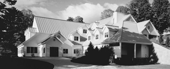
Figure 16.53 This lightweight steel Quonset hut structure is clad with curved roof panels on its roof and flat panels on its walls. The panels are attached with exposed mechanical fasteners made watertight with resilient washers.
The minimum recommended slope for architectural sheet metal roofing is 1:12 (8 percent) for standing-seam roofing and 3:12 (25 percent) for flat-seam or batten-seam roofing. In some configurations, lower slopes can be achieved with special seam treatments, such as making seams taller, soldering seams, or treating seams with elastomeric sealant. As noted earlier in this chapter, some structural configurations of structural sheet metal roofing are designed to remain watertight at slopes otherwise reserved for low-slope membrane roof systems.
Protection from Corrosion Between Dissimilar Metals
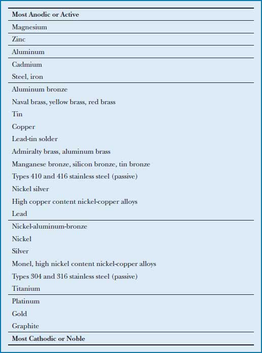
When different metals come in contact in the presence of moisture, corrosion can occur. This phenomenon is discussed in greater detail later in this chapter. The ideal way to avoid such corrosion is to use the same metal for every component of a sheet metal roof system, including its fasteners, anchor clips, roofing metal, flashings, gutters, and downspouts. However, sheet metal roofs made with relatively soft copper, lead, or zinc are frequently anchored with harder, stronger stainless steel clips and fasteners. Because the stainless steel components are relatively small in area and electrochemically noble (passive) in relation to these other metals, the risk of corrosion between metals is minimized.
- A roof can capture rainwater and snowmelt and conduct them to a cistern, tank, or pond for use as domestic water, industrial water, or irrigation.
- A properly proportioned overhang can shade south-facing windows from the high summer sun but admit warming light from the low winter sun.
- A light-colored roof covering, if kept clean, can reflect half or more of the solar radiation striking its surface, improving occupant comfort and reducing the heating load on the occupied space below. Even darker-hued roof materials, when coated with specially formulated cool color pigments, can reflect 25 percent or more of solar radiation. Such cool roofs can reduce cooling energy costs for buildings by 10 to 25 percent and extend the life of the roofing materials.
- Reflective roofs that reduce the absorption of solar heat can decrease the elevation of air temperatures in densely built areas, thereby reducing a building's indirect contributions to smog, degraded air quality, environmental discomfort, and other heat island effects.
- In a hot climate, a shading layer above a roof, with a freely ventilated space between, can eliminate most solar heat gain through the roof surfaces. The shading layer might consist of latticework, fabric, or corrugated metal; the exact material is less important than providing both shading and ventilation.
- A roof surface can support flat-plate solar heat collectors used to reduce building heating costs or arrays of photovoltaic solar modules to provide electrical power. Electrical power for building use can also be produced from thin-film photovoltaic materials laminated directly onto a variety of conventional roof coverings.
- Roof membranes coated with photocatalytic materials can convert various air pollutants into harmless organic materials in the presence of sunlight. Rain then washes the resulting organic material off the roof.
- Bituminous roofing is largely based on asphaltic compounds derived from coal and petroleum.
- Roofing operations with hot asphalt and pitch give off plentiful quantities of fumes that are decidedly unpleasant and potentially unhealthful, but once the roof has cooled, these emissions subside.
- Most roofing felts today are made with cellulose or glass fibers, but very old felts in buildings being demolished or reroofed may contain asbestos, a proven carcinogen.
- The various rubber and plastic formulations used in single-ply membranes generally utilize petroleum as the primary raw material. Each has its own characteristics with regard to embodied energy and outgassing.
- Chemicals associated with the manufacture, use, and disposal of polyvinyl chloride are associated with a variety of severe health effects and serious environmental problems. PVC is on the Living Building Challenge Red List, meaning it should not be used at all in buildings meeting this standard. The use of materials containing vinyl chloride, an ingredient in the manufacture of PVC, is also discouraged in a variety of the LEED standards.
- Adhesive bonding, solvent welding, and heat welding of seams may give off volatile organic compounds (VOCs). Some single-ply membrane materials also emit VOCs.
- Materials from demolition of built-up roof membranes are generally incinerated or taken to landfills. Thermoplastic single-ply membranes can be recycled, although at present most are not. Thermosetting membranes cannot be recycled.
- Low-slope roofs may be developed as green roofs, in which the membrane is covered with soil and plants. These living constituents of the roof consume carbon dioxide, generate oxygen, shield the membrane and the inhabited space below from temperature extremes, cool the roof surface by evaporation and transpiration, delay the passage of stormwater into sewers and reduce its volume, and create a pleasant roofscape.
- Asphalt shingles consist mostly of petroleum.
- The environmental impact of wood shingles is much the same as that of other wood products; see Chapter 3.
- Slates are quarried stone, and concrete tiles are, of course, concrete, the sustainability of which are discussed in Chapter 9 and Chapter 13, respectively.
- Copper, stainless steel, aluminum, terne, and lead roofing materials originate as ores that must be mined, refined, and manufactured into finished form, all at various environmental costs.
- Metal roofing materials can be recycled. There is little recycling of the other steep roof materials. There are available, however, proprietary shingles made almost entirely of recycled tires or other recycled materials.
COOL ROOFS
Roofs are exposed to solar radiation daily, and as that radiation is absorbed and converted to heat, the temperature of the roof covering rises. Depending on the intensity of the radiation and the portion of it retained by the covering, roof surfaces may routinely reach temperatures of 150 degrees Fahrenheit (65°C) or higher. High roof temperatures can lead to overheating of interior spaces; reduced comfort for building occupants; increased building energy consumption; the need for larger, more expensive cooling equipment; shortened life span of roofing materials; and an increased contribution to urban heat island effects through elevation of the surrounding air temperature. Selecting a cool roof covering that minimizes such heating can reduce these effects.
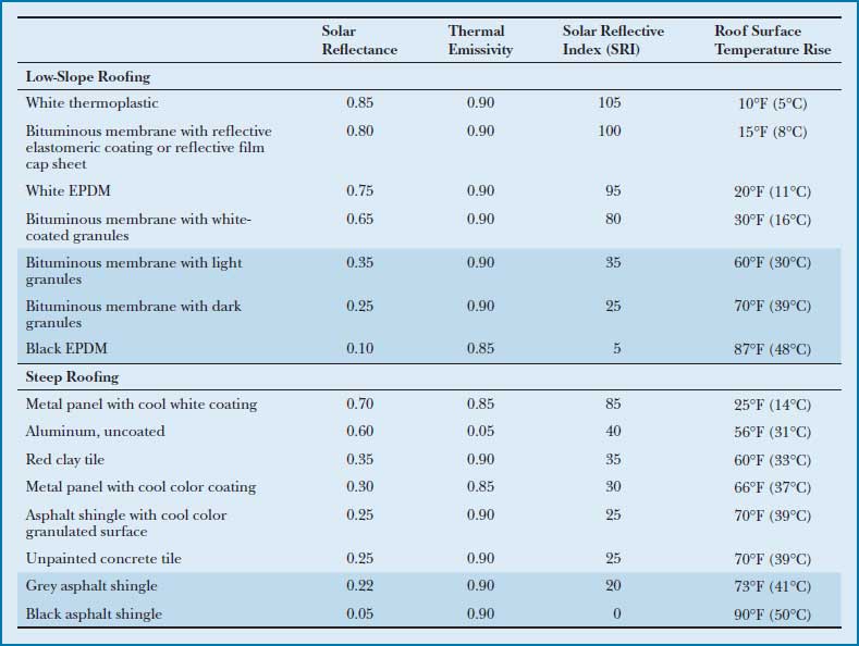
Solar heating of roofs is principally affected by two properties of the roofing material. A material's solar reflectance, or albedo, is a measure of its tendency to reflect solar radiation rather than absorb it. Solar reflectance is measured on a unitless scale from 0 to 1, where 1 represents a material that reflects all solar radiation and 0 represents one that absorbs all solar radiation. A higher solar reflectance corresponds to a cooler roof. Thermal emittance is a measure of a material's capacity to radiate infrared heat energy and cool itself as its temperature rises. Like solar reflectance, thermal emittance is measured on a scale of 0 to 1, and a higher thermal emittance implies a cooler roof.
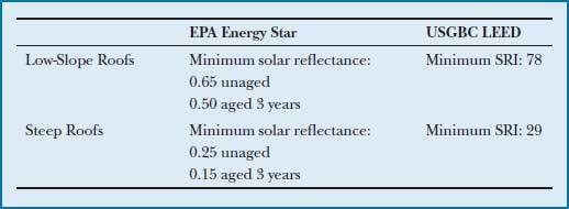
Cool roof criteria differ among energy conservation standards and green building programs. Requirements for the U.S. Environmental Protection Agency's (EPA) Energy Star program are based solely on a roof covering's solar reflectance, measured both when the covering is new and after it has weathered. Requirements for the U.S. Green Building Council's LEED for New Buildings are based on a roof covering's solar reflective index (SRI). SRI is a measure of solar heating potential, derived according to ASTM E1980, that accounts for a material's reflective and emittive properties, as well as for its ability to lose heat through thermal conductance to the surrounding air. Two roofing materials with the same SRI are expected to achieve the same surface temperature under comparable exposures. Higher SRI values correspond to cooler roof coverings, with an SRI value of 0 corresponding to a standard reference black surface and a value of 100 corresponding to a standard reference white surface (Figure 16.54).
Figure 16.54 Cool roof requirements for low-slope and steep roofs. For EPA Energy Star programs, aged values are based on testing of material samples taken from installed, weathered roofs or from samples that have undergone accelerated aging to simulate natural weathering.
Comparative solar heating properties for common roofing materials are listed in Figure 16.55. Product-specific data can be obtained from the manufacturer's product literature or the Cool Roof Rating Council, an independent organization that maintains a roof material rating program and publishes the properties of tested products (see the list of web sites at the end of this chapter). In comparison to traditional dark-colored EPDM or bituminous membranes, reflective cool membranes on low-slope roofs can reduce roof surface temperatures by as much as 50 to 75 degrees Fahrenheit (25–40°C) and cut building cooling costs by an estimated 15 to 25 percent. Cool roofing materials on steep roofs have the potential to save an estimated 5 to 10 percent of building cooling costs.
Figure 16.55 Solar heating properties for common roof materials. Materials in shaded rows do not meet the criteria for cool roofs listed in the previous figure. Figures are approximate and should not be used to document compliance with cool roof rating programs.
Cool color roofing materials are nonwhite in color but nevertheless reflect a significant portion of the sun's radiation. Cool colors are formulated with pigments that are selectively reflective to different portions of the solar spectrum. They are highly reflective of near-infrared (NIR) radiation, an invisible component of solar radiation that accounts for more than half of the total heat energy radiated by the sun, while they remain selectively absorptive in the visible light spectrum, which accounts for their apparent color. Cool color pigments can be applied to aggregate granules used to coat asphalt shingles, as well as to sheet metal, clay or concrete tile, fiber-cement shingles, and other roofing materials to produce products meeting cool roof standards for steep roofs. As the formulation of cool color pigments continues to evolve, smooth-surfaced roofing materials with reflectance values as high as 0.45 and granule-surfaced materials with values as high as 0.30 are anticipated.
GREEN ROOFS
Green roofs, also called vegetated roofs, are roofing systems covered with vegetation, soil, and additional materials needed to support plant growth. Like protected membrane roofs, green roofs extend the life of the roof membrane by shielding it from UV radiation and extremes of temperature. Green roofs may also reduce heating and cooling costs by moderating temperature swings in the roof assembly. They reduce the transmission of noise through the roof system and decrease the reflection of exterior noise. They reduce stormwater runoff and provide habitat for birds and insects. By supporting plant growth and reducing heat island effects, green roofs improve air quality. They provide aesthetic value and, in some cases, create pleasant, usable space.
Extensive green roofs are relatively shallow, with soil depths of 2 to 6 inches (25–150 mm). They are planted with herbs, grasses, mosses, sedums, or other drought-tolerant plants that do not require irrigation or frequent maintenance (Figures 16.56 and 16.59). Intensive green roofs may have soils as deep as 30 inches (750 mm) and are designed to support a broader variety of plant types and shrubs. Intensive roofs require irrigation and regular maintenance such as weeding, trimming, pest management, and fertilization.
Figure 16.56 A green roof over a sloping roof deck. This extensive planted roof has a 6-inch (150-mm)-deep soil layer and supports native and ornamental grasses. (Design by John Senhauser Architects. Photo courtesy of Steve Grim.)

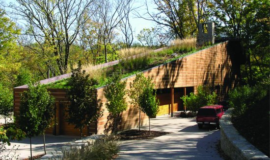
Figure 16.57 A rooftop-mounted array of photovoltaic modules. Each module is composed of a series of round tubes coated with thin-film PV material. The PV tubes convert light coming from any direction, such as directly from the sun, from the diffuse sky on cloudy days, or reflected back from the cool white roof membrane. This array, situated in the relatively cloudy Pacific Northwest, covers 2.5 acres of roof area and is capable of generating more than 830,000 kWh of electricity annually. (Photo by Joseph Iano.)
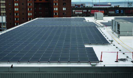
Figure 16.58 A house is both roofed and sided with red cedar shingles to feature its sculptural qualities. (Architect: William Isley. Photo by Paul Harper. Courtesy of Red Cedar Shingle and Handsplit Shake Bureau.)
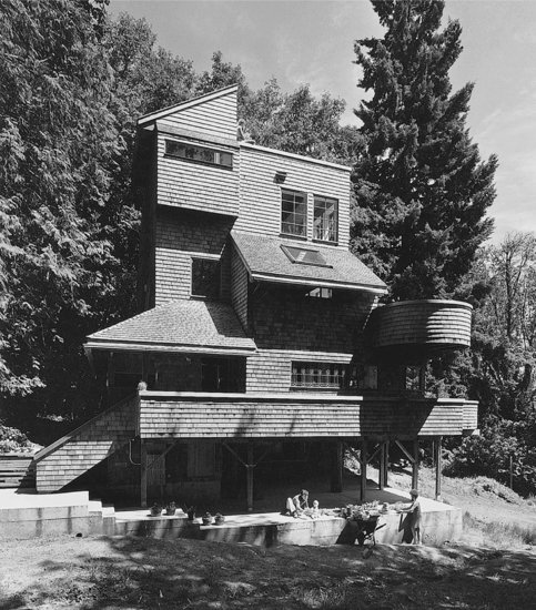
Figure 16.59 Built on a steep slope, the roofs of the building below have a strong presence in the landscape and view beyond. Plantings on the green roof integrate with the terraced landscaping in the foreground while the standing-seam sheet metal contrasts with the body of water beyond. (Photo by Joseph Iano.)
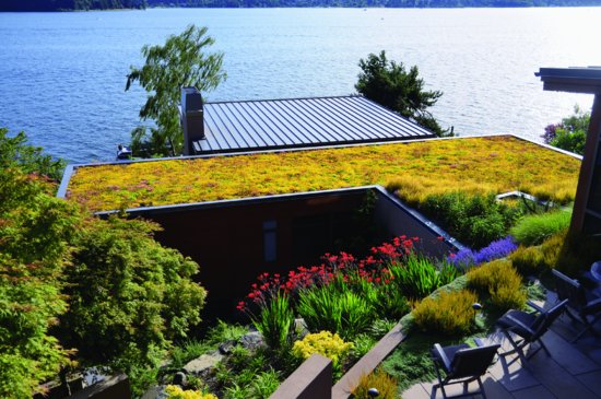
Planning for the structural loads of soil and plant materials is an important part of green roof design. Because of their lesser depth, extensive roofs are relatively light in weight, imposing loads, when saturated with water, ranging from 12 to 35 psf (0.57 to 1.7 kPa) on the supporting roof structure. Intensive roofs impose loads of 50 psf (2.4 kPa) or more. Although most green roofs are essentially flat, extensive roofs with slopes as great as 12:12 (100 percent) are technically feasible with special soil retention measures.
From the top down, typical components of a green roof system include the following:
- Plant materials may be selected on the basis of hardiness, climate, depth of soil, maintenance expectations, and appearance.
- The growth medium (soil) must provide long-lasting, optimal growing conditions. Particulars of its formulation vary with the depth of soil and the types of vegetation supported. Soil stability, drainage properties, and, in extensive roofs, drought resistance are important considerations.
- A geotextile filter fabric prevents soil particles from being washed out of the growth medium and clogging the drainage layer below.
- Soil restraints made from perforated plastic or metal allow the free flow of water while confining the growth medium at the roof perimeter and around drains or scuppers.
- Drainage layer materials, such as a molded plastic panel or an entangled plastic filament mat, provide efficient drainage and aeration beneath the soil. Some products also provide water retention, benefiting the plants' subsoil environment. Crushed rock or other aggregate material may also be used, although at the cost of added weight in comparison to the use of manufactured drainage components.
- Rigid foam insulation boards may be positioned above or below the roof membrane. Where insulation is placed above the membrane, extruded polystyrene is used because it retains its insulating value when wet. Insulation boards must be sufficiently dense and strong in compression to resist the weight of the soil and plant materials above.
- Depending on the membrane system, one or more protection layers to prevent root invasion and to relieve physical stress may be laid over the membrane.
- Because access to the waterproofing membrane becomes difficult once it is covered with the green roof components, it should be chosen after careful consideration of its long-term performance in a buried, continuously damp environment. Especially for intensive green roofs, robust waterproofing systems are recommended in place of lighter-duty, conventional roof membranes. Though many membrane materials may be used, hot rubberized asphalt, PVC, and multi-ply modified bitumen have the longest track records of successful installations. Where modular green roof systems are used (see discussion following) and the membrane will remain more easily accessible, less expensive conventional roof membrane types may also be suitable. Prior to being covered, green roof membranes may be flood tested, that is, tested for watertightness by placing the membrane under continuously submerged conditions for a period of hours or days, to check for leaks prior to placing the overlying components.
- Requirements for the vapor retarder and air barrier are no different for green roofs than for conventional low-slope roof assemblies.
- The roof deck and supporting structure must be engineered to carry the additional loads imposed by green roof components.
With modular green roof systems, all the components of the green roof system above the membrane are preassembled in easily transported trays or modules. These trays, typically 2 to 4 feet (600–1200 mm) in plan dimension and 2 to 8 inches (50–200 mm) in depth, are preplanted and arrive on the construction site ready to be placed directly over the roof membrane. Modular green roof systems are relatively lightweight, easy to specify, easy to assemble on site, and easy to remove or adjust at a later date.
PHOTOVOLTAIC SYSTEMS
Photovoltaic (PV) materials directly convert sunlight to electricity. PV modules, also called solar panels, are made of collections of individual photovoltaic semiconductor wafers interconnected to produce direct current electricity at a specified voltage. Collections of such modules, called PV arrays, are mounted to the building roof or exterior walls (Figure 16.57). Building-integrated photovoltaics (BIPVs) are conventional building materials laminated with thin-film PV semiconductor materials, also interconnected into arrays. BIPVs serve both the traditional functions of cladding, roofing, or glazing, as well as the production of electricity from sunlight.
Electricity produced by any type of PV array is fed through equipment that regulates and converts the direct current output of the PVs to alternating current at typical building power voltages. Where permitted by the public utility, this power may be sold back into the utility grid and used to offset power consumption charges. Or, in a stand-alone or off-grid PV system, PV power is fed into rechargeable batteries or some other type of storage system, and then drawn for use on demand.
Estimating the potential power contribution of a photovoltaic system and evaluating its potential economic payback for a particular project require an analysis of the project's solar exposure, projected power needs, and utility costs. See the list of web sites at the end of this chapter for more information.
ROOFING AND THE BUILDING CODES
For most types of roofing, manufacturing standards, minimum slopes, underlayment materials, and installation requirements are specified by building codes. Codes also regulate a roof's required level of resistance to flame spread and fire penetration, tested according to standards ASTM E108 or UL 790 and rated as Class A, B, or C roof coverings (listed here in decreasing order of resistance). The International Building Code requires roofs to meet Class B requirements on most buildings of Construction Types I, II-A, III-A, IV, or V-A, or Class C requirements on other types (see Figure 1.4 for an explanation of construction types). Roofs for single-family homes and other small residential or utility buildings generally may be nonclassified, except that where portions of such roofs are located close to property lines, a minimum Class C rating is required. Property insurance policies or local building regulations, such as may apply in dense urban areas or in areas prone to wildfire, may also impose roof class rating requirements.
Roof class rating tests apply to whole roof assemblies, including the membrane, shingles or other covering, underlayments, insulation, decking, and ballast, if any. Broadly speaking, most low-slope roof membranes and noncombustible tiles (such as concrete or clay) can meet Class A requirements, as can some metal roof coverings and asphalt shingles made of glass felts. Asphalt shingles made of organic felts can meet Class B requirements. Fire-retardant wood shingles and shakes can meet Class C requirements.
Figure A The galvanic series for selected metals, immersed in flowing sea water, adapted from ASTM G82. When paired as galvanic couples, metals positioned higher on the list will sacrificially corrode while protecting metals positioned lower on the list. The horizontal lines in the list separate metals into groups, with roughly equal ranges of potential difference. For example, although aluminum bronze and lead appear relatively far apart on the list, their electrochemical potential difference is roughly as great as that between nickel-aluminum-bronze and titanium or cadmium and steel. Some metals, such as the stainless steel alloys, can appear in different locations within the series, depending on their chemical state and the environment in which they are placed. In this series, stainless steels are listed in their so-called passive states, their expected condition under normal usage.
KEY TERMS
REVIEW QUESTIONS
1. What are the major differences between a low-slope roof and a steep roof? What are the advantages and disadvantages of each type?
2. Discuss the three positions in which thermal insulation may be installed in a low-slope roof, and the advantages and disadvantages of each.
3. Explain in precise terms the function of a vapor retarder in an exterior wall or roof assembly.
4. Compare a bituminous roof membrane to a single-ply roof membrane.
5. What is the difference between cedar shingles and cedar shakes?
6. What metals are used for architectural sheet metal roofing? What are the strengths and drawbacks of each?
7. What are the benefits of a cool roof? What properties of a roofing material affect its solar heating and how?
8. List the major components of a green roof system and describe their functions.
9. Which of the following metal combinations are generally safe, and why?
a. Copper sheet metal roofing with stainless steel fasteners
b. Copper sheet metal roofing with copper fasteners
c. Copper sheet metal roofing with galvanized steel fasteners
d. Galvanized steel sheet metal roofing with stainless steel fasteners
e. Galvanized steel sheet metal roofing with galvanized steel fasteners
EXERCISES
1. For a low-slope-roofed university classroom building with a masonry bearing wall, steel interior frame, corrugated steel roof deck, and parapet:
a. Show two ways of achieving a 1:50 roof slope on structural bays 36 feet (11 m) square.
b. Sketch a set of details of the parapet edge, building separation joint, area divider, and roof drain for a low-slope roof system of your choice. Show insulation, vapor retarder (if any), roof membrane, and flashings.
2. Sketch a fascia detail for a low-slope roof system of your choice, assuming that the wall below is made of precast concrete panels and the roof deck of precast concrete slab elements.
3. Find a low-slope roof system being installed and take notes on the process until the roof is completed. Ask questions of the roofers, the architect, or your instructor about anything you don't understand.
4. Examine a number of low-slope roofs around your campus or neighborhood, looking for problems such as cracking, blistering, tearing, and leaking. Attempt to explain the reasons for each problem that you discover.
SELECTED REFERENCES
ASHRAE. ASHRAE Handbook—Fundamentals. Atlanta, GA, American Society of Heating, Refrigerating, and Air-Conditioning Engineers, updated regularly.
This handbook provides a definitive treatment of the physics of heat and moisture transfer through building assemblies and the application of these principles to building construction methods.
National Roofing Contractors Association. The NRCA Roofing Manual: Steep-Slope Roof Systems; The NRCA Roofing Manual: Architectural Metal Flashing, Condensation Control and Reroofing; The NRCA Roofing Manual: Membrane Roof Systems; The NRCA Roofing Manual: Metal Panel and SPF Roof Systems. Rosemont, IL, Author, updated regularly.
These manuals, all updated regularly, are the most comprehensive guides to current U.S. practice for low-slope and steep-slope roofing systems. The treatment is exhaustive, and both diagrams and text are excellent. These products may also be available in combined editions.
Sheet Metal and Air Conditioning Contractors National Association. Architectural Sheet Metal. Chantilly, VA, Author, updated regularly.
Architectural sheet metal roofs are copiously detailed in this excellent reference, along with every conceivable flashing, fascia, gravel stop, and gutter for flat and shingled roofs.
Zahner, L. William. Architectural Metals: A Guide to Selection, Specification, and Performance (3rd ed.). Hoboken, NJ, John Wiley & Sons, 1995.
This is one of the most comprehensive treatments available regarding architectural metal types and their uses in construction.
WEB SITES
Roofing
Author's supplementary web site: www.ianosbackfill.com/16_roofing
Low-Slope Roofs
Asphalt Roofing Manufacturers Association: www.asphaltroofing.org
Carlisle SynTec: www.carlisle-syntec.com
Firestone Building Products: www.firestonebpco.com
National Roofing Contractors Association: www.nrca.net
Polyisocyanurate Insulation Manufacturers Association: www.polyiso.org
Whole Building Design Guide, Roofing Systems: www.wbdg.org/design/env_roofing.php
Steep Roofs
Asphalt Roofing Manufacturers Association: www.asphaltroofing.org
Cedar Shingle and Shake Bureau: www.cedarbureau.org
Certainteed Roofing Products: www.certainteed.com
Copper Development Association: www.copper.org
GAF Roofing Products: www.gaf.com
Metal Construction Association: www.metalconstruction.org
Sheet Metal and Air Conditioning Contractors National Association: www.smacna.org
Umicore Building Products (zinc roofing): www.vmzinc-us.com
Cool Roofs
Cool Metal Roofing Coalition: www.coolmetalroofing.org
Cool Roof Rating Council: www.coolroofs.org
Photovoltaic Roofs
Renewable Resource Data Center (RReDC): www.nrel.gov/rredc/
