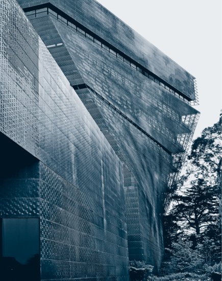
The de Young Museum, San Francisco, by architect Herzog & de Meuron. The building outer skin consists of perforated copper panels allowed to patina naturally. (Photo by Joseph Iano.)
19
DESIGNING EXTERIOR WALL SYSTEMS
Design Requirements for the Exterior Wall
Controlling the Radiation of Heat
Controlling the Conduction of Heat
Secondary Functions of the Exterior Wall
Conceptual Approaches to Watertightness in the Exterior Wall
Rainscreen Cladding and Pressure-Equalized Wall Design
Sealing Joints in the Exterior Wall
Loadbearing Walls and Curtain Walls
Curtain Wall Testing and Standards
The Exterior Wall and the Building Codes
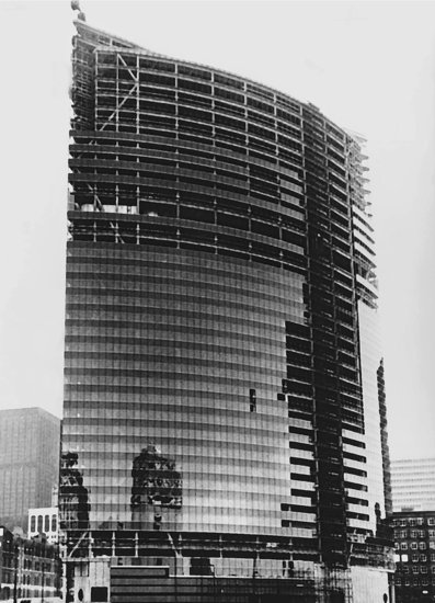
Figure 19.1 A steel-framed Chicago office building during the installation of its aluminum, stainless steel, and glass curtain wall cladding. Notice the diagonal wind braces in the steel frame. (Architects: Kohn Pederson Fox/Perkins and Will. Photo by Architectural Camera. Permission of American Institute of Steel Construction.)
DESIGN REQUIREMENTS FOR THE EXTERIOR WALL
The major purpose of the exterior wall is to separate the indoor environment of a building from the outdoors in such a way that indoor temperature, humidity, and other conditions are maintained at levels suitable for the building's intended use. This translates into a number of separate and diverse functional requirements.
Keeping Water Out
The exterior wall must prevent the entry of rain, snow, and ice into a building. This requirement is complicated by the fact that water on the face of a building is often driven by wind at high velocities and air pressures, not just in a downward direction but in every direction, even upward. Water problems are especially acute on tall buildings, which present a large profile to the wind at altitudes where wind velocities are much higher than at ground level. Enormous amounts of water must be drained from the windward face of a tall building during a heavy rainstorm, and the water, pushed by wind, tends to accumulate in crevices and against projecting mullions, where it will readily penetrate the smallest crack or hole and enter the building. A considerable portion of this chapter is devoted to methods for keeping water out.
Controlling Light
The exterior wall of a building must control the passage of light, especially sunlight. Sunlight is heat that may be welcome or unwelcome. Sunlight is visible light, useful for illumination but bothersome if it causes glare. Sunlight includes destructive ultraviolet (and other) wavelengths that must be kept off human skin and away from interior materials that will fade or deteriorate. Windows should be placed and proportioned with these considerations in mind. Exterior wall systems sometimes include external shading devices to keep light and solar heat away from windows. The glass in windows is often selected to control light and heat, as discussed in Chapter 17. Interior shades, blinds, and curtains may be added for further control.
Controlling Air Leakage
The exterior wall of a building must limit the unintended passage of air between indoors and outdoors. At a gross scale, this is necessary to regulate air velocities and temperatures within the building. Air leaks waste conditioned (heated or cooled) air and increase the chance of water vapor condensation within the wall. Air leakage can also result in reduced occupant comfort and higher concentrations of indoor air pollutants. Sealants, gaskets, weatherstrips, and air barrier membranes of various types are all used to prevent air leakage through the exterior wall. The role of air barriers in controlling air leakage through the building enclosure is discussed in more detail later in this chapter.
Controlling Water Vapor
The exterior wall of a building must retard the passage of water vapor by diffusion through the wall materials. In the heat of summer or the cold of winter, vapor moving through a wall assembly may condense inside the assembly and cause staining, loss of insulating value, corrosion of metals, and decay of wood.
Controlling the Radiation of Heat
Beyond its role in regulating the flow of radiant heat from the sun, the exterior wall of a building should also present interior surfaces at temperatures that will not cause radiant discomfort for building occupants. A cold interior surface will make people feel chilly when they are near the wall even if the air in the building is warmed to a comfortable level. A hot interior surface or direct sunlight in summer can cause overheating of the body despite the coolness of the interior air. External sun shading devices, adequate thermal insulation and thermal breaks, and appropriate selection of glass are potential strategies for controlling heat radiation.
Controlling the Conduction of Heat
The exterior wall of a building must resist the conduction of heat into and out of the building. This requires not merely satisfactory overall resistance of the wall to the passage of heat, but also avoidance of thermal bridges, wall components such as metal framing members that are highly conductive of heat and therefore likely to cause localized condensation on interior surfaces. Thermal insulation, appropriate glazing, and thermal breaks are used to control heat conduction through the exterior wall, as we will observe in Chapters 20 and 21. Building codes specify minimum values of thermal resistance of wall components as a way of limiting the conduction of heat and also as a way of controlling the condensation of moisture on cold interior surfaces.
Controlling Sound
The exterior wall further serves to isolate the inside of a building from noises outside and vice versa. Noise isolation is best achieved by walls that are airtight and massive, and possibly with the inclusion of interior layers that are heavy yet resilient. The required degree of noise isolation varies from one building to another. For example, the exterior wall for a hospital near a major airport requires more noise isolation than that for a commercial building in a suburban office park.
Secondary Functions of the Exterior Wall
Fulfillment of the primary functional requirements of the exterior wall leads unavoidably to a secondary but equally important set of requirements.
Resisting Wind Forces
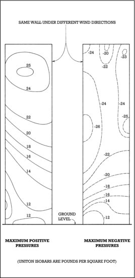
The exterior wall of a building must be strong and stiff enough to sustain the pressures and suctions imposed upon it by the wind. For low buildings, which are exposed to relatively predictable winds, this requirement is fairly easily met. The upper reaches of taller buildings are beset by much faster winds, whose directions and velocities are often made more complicated by aerodynamic effects from surrounding buildings. Both high pressure and suction forces can occur on some portions of the exterior wall, especially near corners of the building (Figure 19.3).
Figure 19.2 The curtain wall of Chicago's Reliance Building, built in 1894–1895, has spandrels constructed of white terracotta tiles. (Architect: Charles Atwood, of Daniel H. Burnham and Company. Photo by Wm. T. Barnum. Courtesy of Chicago Historical Society ICHi-18294.)
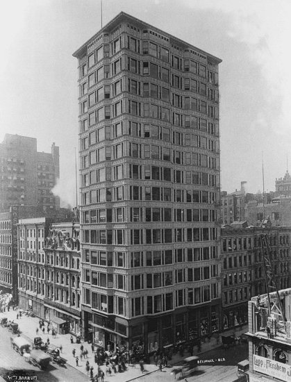
Figure 19.3 An example of positive and negative wind pressures acting on the cladding of a tall building, shown here in elevation, as predicted by wind tunnel testing. The building in this case is 64 stories tall and triangular in plan. Notice the high negative pressures (suctions) that can occur on the upper regions of the facade. The wind pressures on a building are dependent on many factors, including the shape of the building, its orientation, topography, wind direction, and the effects of surrounding buildings. Each building must be modeled and tested individually to determine the pressures it should be expected to encounter. (Reprinted with permission from AAMA Aluminum Curtain Wall Design Guide.)
Adjusting to Movement
Various forces are always at work throughout a building, tugging and pushing both the frame and the exterior wall: thermal expansion and contraction, moisture expansion and contraction, and structural deflections, to name a few. These forces must be accommodated in the design of the building enclosure.
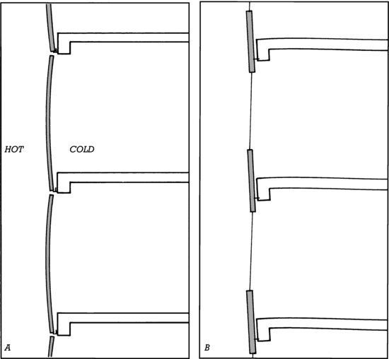
The exterior wall must tolerate movements caused by changes in temperature: Indoor/outdoor temperature differences can cause warping of cladding panels due to differences in differential expansion and contraction on opposite sides of the panels (Figure 19.4A). Different materials within the exterior wall, such as aluminum, steel, glass, and concrete, each expand and contract at different rates in response to changes in temperature. Portions of the exterior wall as a whole, exposed to outdoor temperature variations, expand and contract constantly with respect to the structural frame of the building. Where parts of a building frame are exposed to the exterior, they exhibit their own expansion and contraction behavior. And even where the building frame is within the insulated envelope of the building, it expands and contracts to some extent, especially between the time the exterior wall is installed and when the building is first occupied and its indoor temperature is controlled.
Figure 19.4 Distortions of curtain wall panels, illustrated in cross section. (A) Bowing, caused in this case by greater thermal expansion of the outside skin of the panels than of the inside skin under hot summertime conditions. (B) Twisting of spandrel beams because of the weight of the curtain wall.
The exterior wall must accommodate expansion and contraction caused by variations in moisture content: Fired clay bricks, which leave the kiln with a very low moisture content, expand after they are installed as they absorb moisture from the atmosphere. Many building stones also expand slightly after they are installed. Concrete masonry units and precast concrete shrink by small amounts after installation as their curing is completed. Such movements, though small, can nevertheless accumulate to the extent that materials become distressed or distorted, or even fail completely. In smaller buildings, wood cladding components are most susceptible to moisture movement, as discussed in Chapters 3 and 6.
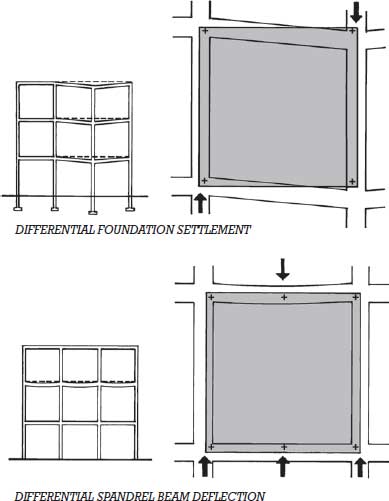
The exterior wall must adjust to structural movements in the frame of the building: Building foundations may settle unevenly, causing distortions of the frame. Gravity forces shorten columns and cause beams and girders to which the exterior wall system is attached to sag slightly. Wind and earthquake forces push laterally on building frames and wrack panels attached to the faces. Long-term creep causes significant shortening of concrete columns and sagging of concrete beams and slabs during the first year or two of a building's life. Posttensioning of concrete components causes significant dimensional contraction in the early life of the structure.
If the exterior wall design does not adequately account for movement between it and the building frame, wall materials can be damaged or the performance of the wall compromised, with results varying from minor aesthetic effects to the need for wholesale replacement of the wall system. Where joints in the wall system become overstressed, leakage of air or water can cause exterior staining, damage to interior finishes, or mold and corrosion within the wall. Where glass panels are impinged by their surrounding frames, they may break. Where cladding materials become overstressed, they may buckle, crack, or fail completely and fall from the building. Strategies for dealing with movement from all these causes are evident in the details of exterior wall systems presented in Chapters 20 and 21 (Figure 19.5).
Figure 19.5 Forces on curtain wall panels caused by movements in the frame of the building, illustrated in elevation. In each of the six examples, the drawing to the left shows the movement in the overall frame of the building, and the larger-scale drawing to the right shows its consequences on the curtain wall panels (shaded in gray) covering one bay of the building. Points of attachment between the panels and the frame are shown as crosses. The black arrows indicate forces on the wall panels caused by the movement in the structure. The magnitude of the structural movements is exaggerated for clarity, and some inadvisable attachment schemes are shown to demonstrate their consequences. Forces such as these, if not taken into account in the design of the frame and cladding, can result in glass breakage, panel failures, and failure of the attachments between the panels and the frame.
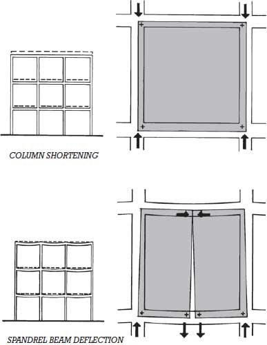
Figure 19.5 (Continued)
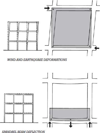
Figure 19.5 (Continued)
- Glass should be used where it can supply daylighting and provide views. If it cannot be effectively shaded, it should be avoided where summertime overheating could otherwise occur or where occupants could be subject to excessive glare at times of the day when the sun is low in the sky.
- In many buildings, windows that can be opened and closed by the occupants can help reduce energy costs.
- Opaque areas of the exterior wall should be well insulated.
- Thermal bridges should be eliminated from the exterior wall.
- The entire building envelope should be detailed for airtightness. Fresh air should be provided by the building's ventilation system, not by air leakage through the exterior wall.
- Where appropriate, south-facing glass can be used to provide solar heat to the building in winter, but care must be taken to avoid glare, local overheating, and ultraviolet deterioration of interior surfaces and furnishings that are exposed to sunlight.
- As photovoltaic cells become more economical, consideration should be given to using south-facing surfaces of the exterior wall to generate electrical energy.
Resisting Fire
Building codes regulate the combustibility and fire resistance of the exterior wall. These issues are addressed in greater length at the end of this chapter.
Weathering Gracefully
To maintain the visual quality of a building, its cladding must weather gracefully. The inevitable dirt and grime should accumulate evenly, without streaking or splotching. Functional provisions must be made for maintenance operations such as glass and sealant replacement and for periodic cleaning, including scaffolding supports and safety equipment attachment points for window washers. The cladding must resist oxidation, ultraviolet degradation, breakdown of organic materials, corrosion of metallic components, chemical attack from air pollutants, and freeze-thaw damage of stone, brick, concrete, concrete block, and tile.
Constructability Requirements for the Exterior Wall
The exterior wall system should be easy to install. There should be secure places for installers to stand, preferably on the floors of the building rather than on scaffolding outside. There must be built-in adjustment mechanisms in the fastenings between components of the wall system and the frame to allow for the inaccuracies that are normally present between these systems. Sufficient clearance must be provided so that components can be installed easily, without interference by other parts. Most importantly, the system must be sufficiently forgiving in its design to allow for a lifetime of trouble-free performance despite the lapses in workmanship or material quality that inevitably occur.
CONCEPTUAL APPROACHES TO WATERTIGHTNESS IN THE EXTERIOR WALL
In detailing the exterior wall for water resistance, we work from a secure theoretical base. In order for water to penetrate a wall, three conditions must be satisfied simultaneously:
If any one of these conditions is not satisfied, the wall will not leak. This suggests three conceptual approaches to making a wall watertight:
This latter approach, called a barrier wall or face-sealed wall, is simple in concept but often difficult in practical application. In a wall made up of many jointed components, all these joints are unlikely to be perfect. If a surface is a bit damp, dirty, icy, or oily, joint sealants may not reliably stick to it. If a worker applying a sealant or gasket is insufficiently skilled, has to reach a bit too far to complete the joint, or is working under cold, wet, or windy conditions that interfere with careful installation, the joint may be left compromised. Even if joints are well made, building movements can tear sealant or pull gaskets loose. Because, in a barrier wall, sealed joints are on the outside of the building, they are exposed to the full effects of sun, wind, water, and ice and may fail over time from weathering and age. Further, whatever the cause of joint failure, joints on the outside face of the wall are difficult to reach for inspection and repair. Thus, in practice, long-term watertightness is often difficult to achieve with barrier wall construction.
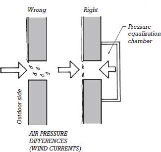
Figure 19.6 The five forces that can move water through an opening in a wall, illustrated in cross section with the outdoors to the left. Each pair of drawings shows first a horizontal joint between wall panels in which a force moves water through the joint, then an alternative design for that joint that neutralizes this force. Leakage caused by gravity is avoided by sloping internal surfaces of joints toward the outside; the slope is called a wash. Momentum can be counteracted with a labyrinth. A drip and a capillary break are shown here as means for stopping leakage from surface tension and capillary action, which are closely related forces. Air pressure differences between the outside and inside of the joint will result in air currents that can transport water through the joint. This is prevented by closing the area behind the joint with a pressure equalization chamber (PEC). When wind strikes the face of the building, pressure in the PEC quickly rises until it is equal to the pressure outside the wall, after which all air movement through the joint ceases. Each joint in an exterior wall, window, or door must be designed to neutralize all five of these forces.
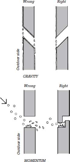
Figure 19.6 (Continued)

Figure 19.6 (Continued)
Gravity is a factor in pulling water through a wall only if the wall contains an inclined plane that slopes into, rather than out of, the building. It is usually a simple matter to detail the exterior wall system so that no such inclined planes exist, though sometimes a loose gasket or an errant bead of sealant can create one despite the best efforts of the designer.
The momentum of falling raindrops can drive water through a wall only if there is a suitably oriented slot or hole that goes completely through the wall. Momentum is neutralized by applying a cover to each joint in the wall or by designing each joint as a labyrinth.
The surface tension of water, which causes it to adhere to the underside of a cladding component, allows water to be drawn into the building. A drip on any underside surface to which water might adhere eliminates the problem.
Capillary action is the surface tension effect that pulls water through any opening that can be bridged by a water drop. It is, for example, the primary force that transports water through the pores of a masonry wall. It can be eliminated as a factor in the entry of water through a wall by making each of the openings in a wall wider than a drop of water can bridge or, if this is not feasible or desirable, by providing a concealed capillary break somewhere inside the opening. In porous materials such as brick, capillary action can be counteracted by applying an invisible water-repellent coating that destroys the adhesive force between water and the walls of the pores in the brick.
The solutions described in the four preceding paragraphs are easy to implement. With relatively straightforward geometric manipulations of the joint, the possibility of leakage caused by four of the five forces that can move water through an opening in a wall can be eliminated. The fifth force, wind pressure, is the most difficult to deal with in designing a wall for watertightness. We can neutralize it by employing pressure-equalized wall design.
Rainscreen Cladding and Pressure-Equalized Wall Design
The solution to the wind current problem is to allow wind pressure differences between the outside and inside of the exterior wall to neutralize themselves through a concept known as pressure-equalized wall design. This involves the creation of an airtight plane, the air barrier, behind the outer face of the wall. The air barrier is protected from direct exposure to the outdoors by an unsealed, labyrinth-jointed layer known as the rainscreen. Between the rainscreen and the air barrier is a space known as the pressure equalization chamber (PEC).
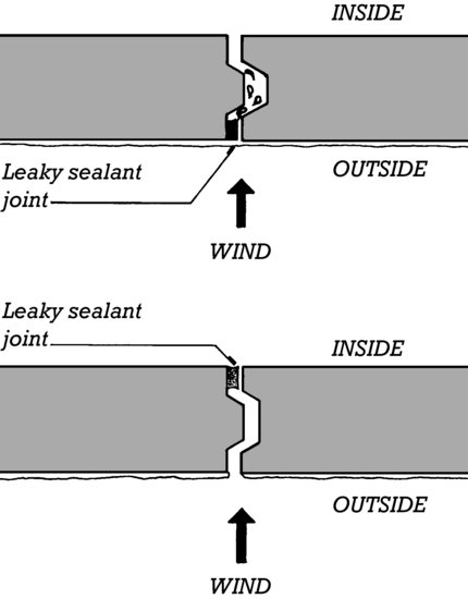
As the wind fluctuates and exerts varying pressures on the exterior wall, small currents of air pass back and forth through each unsealed joint in the rainscreen, just enough to equalize the pressure inside the PEC with the pressure immediately outside it (Figure 19.6). These currents are far too weak to carry water with them. A small flaw in the air barrier, such as a sealant bead that has pulled away from one side of the joint, is unlikely to cause a water leak because the volume of air that can pass through the flaw is insufficient to carry water. By contrast, any flaw, no matter how small, in an external sealant joint in a barrier wall design will allow water to leak through, because the sealant joint itself is wetted (Figure 19.7).
Figure 19.7 Leakage through a defective vertical sealant joint between curtain wall panels, shown in plan view. In the upper example, the sealant joint is at the outside face of the panels, where it is wetted during a storm. Even a small current of air passing through the defective joint carries water with it. In the lower example, with the defective sealant located on the inside of the panels where it remains dry, air leakage through the joint is insufficient to transport water through the joint, and no water penetrates.
Because wind pressures across the face of a building frequently vary considerably at any given moment between one area of the face and another, the PEC must be divided into compartments small enough that volumes of air cannot rush through the joints in higher-pressure areas of the face and flow across the air chamber to lower-pressure areas, carrying water with them as they go. The appropriate size of these chambers may vary considerably, depending on the design of the wall system and the wind forces to which it is exposed. Broadly speaking, PECs are normally no taller than one story or wider than one or two column bays. In some applications they may be significantly smaller.
Simple Rainscreen Design
The term rainscreen principal originated with the concept of pressure-equalized wall design, and at one time was used exclusively in reference to pressure-equalized cladding systems. More recently, the term rainscreen cladding has come to be applied more broadly to any cladding with a system of internal drainage, regardless of the extent of compartmentalization of the drainage space and the degree of pressure equalization that can be achieved. In practice, varying degrees of pressure equalization or moderation occur, and the lines between cladding systems best characterized as simple rainscreens and those considered fully pressure-equalized are often indistinct. To avoid confusion with pressure-equalized systems, simple rainscreen cladding may also be referred to as drained and back-ventilated cladding.
Figure 19.9 illustrates the components of a commercial rainscreen cladding system, and Figure 6.19, a typical residential application. In either case, water that penetrates the outer cladding is captured in the furred space and readily drained out the bottom of the wall. Air circulation behind the cladding further helps to extract moisture from within the furred space. Masonry cavity walls, used on buildings of virtually any size, are another example of rainscreen cladding that frequently incorporates at least some degree of pressure-equalization (Figure 20.3). As we will see in Chapter 21, internal drainage systems are an integral component of every metal-and-glass curtain wall system.
A Pressure-Equalized Wall Design
Figure 19.8 depicts a cladding design that embodies the rainscreen and pressure-equalization principles in simple form. No surface joint sealants or gaskets are used. The metal rainscreen panels do not touch one another, but are separated by generous gaps that preclude capillary movement of water, provide installation clearances, and allow for expansion and contraction. All four edges of each panel are shaped so as to create labyrinth joints. The forces of surface tension and gravity are counteracted by sloping surfaces and drips.
Figure 19.8 The rainscreen in this exemplary cladding system is made up of metal panels, each formed from sheet metal. The design team included Wallace, Floyd Associates, Inc., Bechtel/Parsons Brinckerhoff, Stull and Lee, Inc., Gannett Fleming/URS/TAMS Consultants, and the Massachusetts Highway Department.
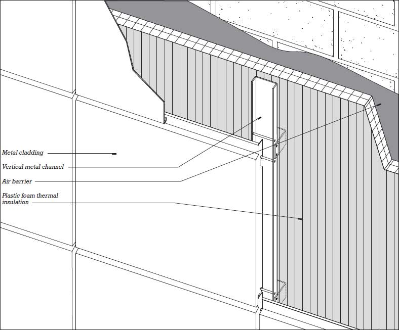
Figure 19.8 (Continued)
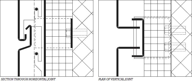
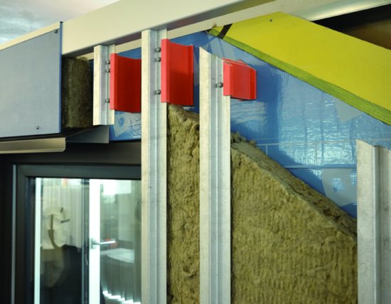
Figure 19.9 A cutaway mockup of a rainscreen wall system. Beginning from the top right and moving down and to the left: The light-colored, diagonal band is glass-mat-faced gypsum sheathing. The narrow dark strip is liquid primer applied to the sheathing. The primer improves the adhesion of the self-adhered membrane (the shinier, reflective dark surface starting below the primer) which acts as an air barrier, water barrier, and vapor retarder in this assembly. Semirigid mineral wool batt insulation is applied continuously over the self-adhered membrane. This material is sufficiently dense and water repellent to maintain its thermal insulation value even in the relatively damp rainscreen drainage space. Vertical galvanized steel furring strips are held away from the sheathing by fiberglass standoffs that have low thermal conductivity and act as thermal breaks between the furring and the remainder of the wall. Finish cladding may be a cementitious or metal panel with gapped joints, directly fastened to the furring strips.
Installation is simple and forgiving of minor lapses in workmanship: Metal U-shaped clips are bolted to the backup wall, which is coated with an airtight mastic to create an air barrier. Rigid insulation panels are adhered to the wall, allowing the clips to project through. Vertical metal channels are bolted to the clips. Finally, the metal panels that make up the rainscreen are simply hung on horizontal rods that are supported by the channels, much as pictures are hung on hooks on a wall. The space between the metal rainscreen panels and the insulation acts as an internal drainage space.
To achieve a pressure-equalized design, horizontal metal angles, not shown, are installed between the channels at one- or two-story intervals. The vertical channels further divide the PEC into narrow compartments. The spaces between the edges of the panels and the channels are narrow enough to restrict airflow sufficiently to achieve a pressurized design. If more complete compartmentalization is needed, compressible foam rods or gaskets can be installed alongside the channels to create more airtight boundaries at these locations. When wind drives rain against this wall, small quantities of air flow through the open joints in the rainscreen until the pressure in the PEC equals the pressure outside. These airflows are insufficient in volume or velocity to carry water with them.
Pressure Equalization at Smaller Scale
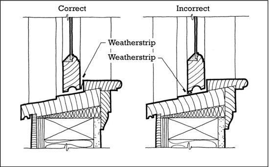
The principles of rainscreen design and pressure equalization may also be applied on a small scale to guide us in many aspects of exterior detailing of buildings. Figure 19.10 demonstrates how this practice is embodied in the placement of weatherstrip in a window sill detail. In the correct detail, the weatherstrip, whose function is to act as an air barrier, is placed to the inside of the lower rail of the sash. The open joint under the sash rail, which is provided with a capillary break, acts as the PEC. Unless the weatherstrip is grossly defective, water cannot be blown through the joint by air pressure differentials. Notice how the other forces that could transport water through the joint are counteracted: A slope on the sill prevents gravity from pulling water in. The groove in the lower edge of the sash that acts as a capillary break also acts as a drip to counteract surface tension. The L-shaped joint between the sash and the sill acts as a labyrinth to prevent entry by momentum. In the incorrect detail, the weatherstrip can be wetted by rain. Any minor flaw in the weatherstrip will allow water to be blown through the joint.
Figure 19.10 Applying the rainscreen principle to the detailing of the sill of a double-hung window. (From Edward Allen, Architectural Detailing: Function, Constructability, Aesthetics, Hoboken, NJ, John Wiley & Sons, Inc.; reproduced with permission of the publisher.)
Relatively few buildings rely completely on the rainscreen principle and pressure-equalized design for watertightness. However, there are very few contemporary cladding systems that do not employ these principles as an important part of their defense against water penetration. Consider again the familiar example of the masonry cavity wall: These principles can be seen in the brick facing wythe acting as a rainscreen, the backup wall as an air barrier, and the cavity, partially pressurized through weep and vent holes, as the PEC. Nevertheless, the surface of the outer masonry veneer is also frequently sealed with compounds to reduce its absorbency (an application of the barrier wall approach), and the cavity is flashed and provided with weep holes so that water that does penetrate the veneer can be safely channeled back to the exterior (an application of internal drainage).
SEALING JOINTS IN THE EXTERIOR WALL
Joint seals are an important part of all exterior wall systems, whether located at the face of the wall or deeper within its construction. The role of the seal is to prevent the passage of air and water while still allowing for necessary dimensional tolerances during assembly and reasonable amounts of movement once construction is complete. Seals are often used between panels of stone or precast concrete in a curtain wall (Figures 20.8 and 20.13), beneath shelf angle in brick curtain walls (Figure 20.3), and between dissimilar materials, such as where a metal-and-glass cladding system ends against a masonry wall (Figure 21.12, details 6, 9, and 9A). Specially formulated sealants are used to seal between lites of glass and the frames that support them (Figure 17.18) and even to prevent the passage of sound around the edges of interior partitions (Figures 23.21, 23.22, 23.34, and 23.37). In general, sealed joints are usually 3/8 to ¾ inch (9–19 mm) in width. But they can be small as ¼ inch (6 mm), and, where anticipated movements are great, 1 inch (25 mm) or wider.
Sealant Materials
Gunnable Joint Sealants
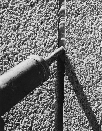
Gunnable joint sealant materials are viscous, sticky liquids that are injected into the joints of a building with a sealant gun (Figure 19.11). They cure within the joint to become rubberlike materials that adhere to the surrounding surfaces and seal the joint against the passage of air and water. Gunnable joint sealants can be grouped conveniently in three categories according to the amount of change in joint size that each can safely withstand after curing:
Figure 19.11 Applying polysulfide, a high-range gunnable sealant, to a joint between exposed-aggregate precast concrete curtain wall panels, using a sealant gun. The operator moves the gun slowly so that a bulge of sealant is maintained just ahead of the nozzle. This exerts enough pressure on the sealant so that it fully penetrates the joint. Following application, the operator will return to smooth and compress the wet sealant into the joint with a convex tool, much as a mason tools the mortar joints between masonry units. (Courtesy of Morton Thiokol, Inc., Morton Chemical Division.)
- Low-range sealants, also called caulks, have very limited elongation (stretching and squeezing) capabilities, up to plus or minus 5 percent of the width of the joint. They are used for filling minor cracks or nonmoving joints, especially in preparation for painting. Most caulks cure by evaporation of water or an organic solvent and shrink substantially as they do so. None are used for sealing joints in building exterior wall systems. (Although the term “caulk” is properly applied only to low-range sealants, in common usage it is frequently applied more broadly to mean any type of sealant, regardless of elongation capability.)
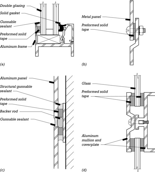
- Medium-range sealants, such as butyl rubber or acrylic, have elongation capacity in the range of plus or minus 5 to 10 percent. They are used in the building exterior wall for sealing nonworking joints (joints that are fastened together mechanically as well as being filled with sealant, such as the preformed solid tape sealant shown in Figure 19.12b). Because these sealants cure by the evaporation of water or an organic solvent, they undergo some shrinkage during curing.
- High-range sealants can safely sustain elongations up to plus or minus 50 to 100 percent. They include various polysulfides, which are usually site mixed from two components to effect a chemical cure; polyurethanes, which may also cure by a two-component reaction or by reacting with moisture vapor from the air, depending on the formulation; and silicones, which cure by reacting with moisture vapor from the air. None of these sealants shrink upon curing because none relies on the evaporation of water or a solvent. All adhere tenaciously to the sides of properly prepared joints. All are highly resilient materials that return to their original size and shape after being stretched or compressed, and all are durable for many years if properly formulated and installed. Sealants for the working joints in exterior wall systems are selected from among this group. Polysulfide sealants have the longest history of use in such applications. However, improved formulations of polyurethanes and silicones now account for 90 percent or more of the high-range construction sealant market, with silicones generally considered the longest lasting and highest performing of the three.
Figure 19.12 (a) Preformed solid tape is adhered to the vertical leg of the aluminum frame. Next, the glazing is inserted and an aluminum glazing bead with a solid gasket is snapped into place, pressing the glazing tightly between the gasket and the solid tape. Lastly, gunnable sealant is installed over the solid tape for a better weather seal. (b) Preformed solid tape seals the nonmoving joint between two adjacent metal panels. (c) Preformed solid tape holds the aluminum panels at a controlled distance from the backing plate. Structural sealant adheres the panels to the backing. (Though not shown here, the backing plate is also fastened to the wall.) A backer rod and gunnable sealant form a weather seal at the face of the panels. Backer rods are discussed in the next section of the text. (d) Preformed solid tape holds sheets of single glass between an aluminum mullion and its coverplate.
Gunnable joint sealants are specified according to ASTM standard C920, which defines designations for sealant Type, Grade, Class, and Use. Type S sealants are single-component and require no job site mixing. Type M sealants are multicomponent and must be mixed on the job site before installation. Multicomponent sealants generally cure faster than single-component sealants. They also allow a greater variety in color choice, as dye packs can be added during mixing. Grade P sealants, also called self-leveling, are pourable. They are easily installed in horizontal paving joints. For vertical wall joints, Type NS, nonsag, sealants must be used. Class defines the elongation capability of a sealant. A Class 25 sealant can tolerate 25 percent expansion and contraction under normal usage. A Class 100/50 sealant (the highest Class designation in the current standard) can tolerate 100 percent expansion and 50 percent contraction. A Use T, traffic, sealant can tolerate wear and physical abuse of pedestrian or vehicular traffic (most pourable sealants are also Use T); a Use NT, nontraffic, sealant is not suitable for traffic exposure and is normally intended for use in vertical wall joints; a Use I, immersible, sealant is suitable for sealing applications that will be submerged once the sealant has cured. Sealants may also be classified as Use M, G, A, or O, meaning that they have passed a series of tests demonstrating satisfactory adherence to mortar, glass, aluminum, or other materials, respectively. As an example, a multicomponent sealant intended for expansion joints between sections of aluminum curtain wall, which must be capable of 50 percent elongation, can be specified as Type M, Grade NS, Class 50, Uses NT and A.
Solid Joint Seal Materials
As an alternative to gunnable sealants, preformed solid materials may be used for various joint sealing needs in exterior wall systems (Figure 19.12):
- Gaskets are strips of fully cured elastomeric (rubberlike) materials manufactured in different configurations and sizes for different purposes, but most commonly dry glazing. They are compressed into a joint to seal tightly against the surfaces on either side.
- Preformed cellular tape sealant is a strip of polyurethane sponge material that has been impregnated with a mastic sealant. It is delivered to the construction site in an airtight wrapper, compressed to one-fifth or one-sixth of its original volume. When a strip is unwrapped and inserted, it expands to fill the joint, and its sealant material cures with moisture from the air to form a watertight seal. Preformed cellular tapes can be used to seal very wide joints, such as occur at seismic separations between large portions of a building.
- Preformed solid tape sealants are used in nonmoving lap joints, as in mounting glass in a metal frame or overlapping two sheets of metal cladding. They are thick, sticky ribbons of polybutene or polyisobutylene that both seal and cushion the joint. They are installed as the joint is assembled, as they are too sticky to be inserted later into the finished joint. They are also stiff enough to maintain a predictable spacing between the elements being joined.
Sealant Joint Design
Figure 19.13 illustrates the principles of joint design for gunnable sealants. Before the sealant is installed, the joint surfaces must be cleaned of oil, dirt, oxide, moisture, concrete form release compound, or other contaminants. Where necessary, the edges of the joint are primed with a suitable coating to improve adhesion between the sealant and the joint surfaces.
Figure 19.13 Good and bad examples of sealant joint design. (A) This properly proportioned joint is shown both untooled and tooled. The untooled sealant fails to penetrate completely around the backer rod and does not adhere fully to the sides of the joint. (B) A narrow joint may cause the sealant to elongate beyond its capacity when the panels on either side contract, as shown to the right. (C) If the sealant bead is too deep, sealant is wasted, and the four edges of the sealant bead are stressed excessively when the joint enlarges. (D ) A correctly proportioned sealant bead. The backer rod, made of a spongy material that does not stick to the sealant, is inserted into the joint to maintain the desired depth. The width is calculated so that the expected elongation will not exceed the safe range of the sealant, and the depth is between 1/8 and 3/8 inch (3 and 9.5 mm). (E) A correctly proportioned lap joint. The width of the joint (the distance between the panels) should be twice the depth of the sealant bead and twice the expected movement in the joint.

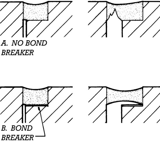
Next, backer rod or backup rod is inserted into the joint. This is a cylindrical strip of compressible, flexible plastic foam that is just a bit larger in diameter than the width of the joint. It is pushed into the joint, where it is held by friction. The backer rod limits the depth to which the sealant will penetrate. This maintains the optimum proportions of the sealant bead and avoids waste of sealant material. It also ensures that only two sides of the sealant adhere to the joint itself. As illustrated in Figure 19.14, sealant adhered on three sides has limited movement capability. Backer rod is available in a large range of diameters to fit every joint.
Figure 19.14 In a three-sided joint, the sealant is likely to tear unless a nonadhering plastic bond breaker strip is placed in the bottom of the joint before the sealant is installed.
Sealant is extruded into the joint from the nozzle of a sealant gun and then mechanically tooled, much as a masonry mortar joint is tooled, to compress the sealant material firmly against the sides of the joint and the backer rod. Tooling also produces a smoother surface and creates the desired surface profile to the sealant. The backer rod's role is now finished but, being inaccessible, it remains in the joint.
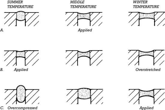
The proper width of the sealant joint depends on the expected range of movement in the joint and the movement capacity of the sealant. For example, a Class 50 sealant (capable of 50 percent elongation or compression) installed into a 1-inch (25-mm) joint is capable of accommodating no more than ½ inch (13 mm) of movement. In practice, this calculation is made more complicated by consideration of variations in joint width due to construction tolerances and other factors. For example, for a joint between materials with high coefficients of thermal expansion, the time of year when the sealant is installed must be taken into account. Sealant installed in cold weather will have to stretch less during its lifetime but will have to compress more in summer than the same sealant installed in hot weather, which will have to stretch more and compress less (Figure 19.15).
Figure 19.15 Sealants are best applied at moderate temperatures. If cold- or hot-weather applications of sealants are anticipated, the joints should be proportioned to minimize overstretching or overcompression. Row A shows the behavior of a sealant applied at a medium temperature. Rows B and C show sealant applied at summer and winter temperatures, respectively.
LOADBEARING WALLS AND CURTAIN WALLS
The Loadbearing Wall
Until the late 19th century, nearly all large buildings were built with loadbearing exterior walls. These walls supported a substantial portion of the floor and roof loads of the building, as well as separating the indoor environment from the outdoors. In noncombustible buildings, these walls were built of brick or stone masonry. Functionally, such walls had several inherent limitations. They were poor thermal insulators, and they were heavy, requiring large foundations and limiting their height to a few stories.
The loadbearing wall has been brought up to date with higher-strength masonry and concrete; components such as thermal insulating materials, cavities, flashings, air barriers, and vapor retarders have been added to make the wall more resistant to the passage of water, air, and heat; and the addition of steel reinforcing has allowed the wall to become thinner, lighter, and better able to resist wind and seismic loads. Loadbearing masonry and concrete exterior walls are often attractive and economical for low- and medium-rise buildings. High-rise residential towers with exterior loadbearing masonry walls also continue to be built, especially in Asia. These types of construction are illustrated and discussed in more detail in Chapters 8, 10, and 14.
The Curtain Wall
The first steel-framed skyscrapers, built in the late 19th century, introduced the concept of the curtain wall, an exterior wall supported at each story by the frame. The name “curtain wall” derives from the idea that the wall is thin and “hangs” like a curtain on the structural frame. (Most curtain wall panels do not actually hang in tension from the frame; rather, they are supported from the bottom at each floor level.) The earliest curtain walls were constructed of masonry (Figure 19.2). The principal advantage of the curtain wall is that, because it bears no vertical load, it can be thin and lightweight regardless of the height of the building, compared to a masonry loadbearing wall, which may become prohibitively thick and weighty at the base of a very tall building.
Curtain walls may be constructed of any noncombustible material that is suitable for exposure to the weather. They may be either constructed in place or prefabricated. In Chapter 20, we will examine curtain walls that are made of masonry and concrete. In Chapter 21, we will look at curtain walls that are made of metal and glass.
Figure A Air pressure differences in a building can be caused by (a) wind, (b) the stack effect, such as within an elevator shaft, and (c) building mechanical systems.
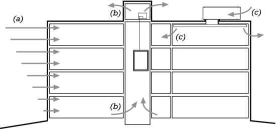
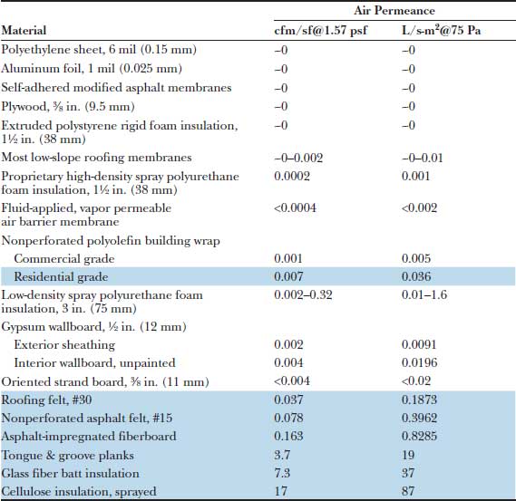
Figure B Air permeance of common building materials. Shaded rows indicate materials exceeding recommended air permeance for air barrier materials.
Curtain Wall Testing and Standards
Structural Performance and Resistance to Wind and Rain
For any new curtain wall design, it is advisable to build and test a full-scale section of wall to determine its resistance to infiltration of air and water and its structural performance under heavy wind loads. There are several outdoor laboratories in North America that are equipped to conduct these tests. A full-scale specimen of the wall system, often two stories high and a bay wide, is constructed as the exterior wall of a chamber that can be pressurized or evacuated by a calibrated blower system.
Curtain wall testing is conducted according to the American Architectural Manufacturers Association standard AAMA 501 Methods of Tests for Exterior Walls, which itself references numerous other standards for specific aspects of the testing. The specimen is tested first for air infiltration, using ASTM E283, in which it is subjected to a static air pressure that corresponds to the pressure that will be created by the anticipated maximum wind velocity in the vicinity of the building. Air that leaks through the wall is carefully measured, and the rate of leakage is compared to specified standards.
A static test for water penetration is next, using ASTM E331: The wall is subjected to a static air pressure while being wetted uniformly across its surface at a rate of 5 gallons per hour per square foot (3.4 L/m2-min). Points of water leakage are noted, and leaking water is carefully collected and measured. A dynamic water penetration test may also be performed in accordance with AAMA 501.1, using an aircraft engine and propeller to drive water against the wall.
The structural performance of the wall is tested according to ASTM E330, in which a calibrated blower subjects the wall specimen to air pressures and suctions as high as 50 percent over the specified wind load, and the deflections of the structural members in the wall are measured. Optionally, tests for thermal performance, sound transmission, and the effects of thermal cycling, seismic loads, and movement of the structure to which the curtain wall is attached may also be performed.
Although all these tests yield numerical results, it is also important that the behavior of the specimen be observed closely during each test so that specific problems with the design, materials, detailing, and installation can be identified and corrected. Most wall system specimens fail one or more of the tests for air and water leakage on the first attempt. By observing the sources of leakage during the test, it is usually possible to modify the flashings, sealants, weep holes, or other components of the design so that the modified specimen will pass the subsequent test. These modifications are then incorporated into the final details for the actual building.
After testing has been completed and final design adjustments have been made, production of the wall components begins, and deliveries to the site can commence as soon as the frame is ready to receive the system.
Curtain wall systems require careful inspection during installation to be sure that there are no defects in workmanship. Even seemingly small imperfections in assembly can lead to large, expensive problems later. As work progresses, installed portions of the curtain wall can be checked for water leakage according to AAMA 501.2. This involves directing water at the joints in the wall with a hose that has a specified nozzle and following specified procedures to isolate the causes of any leaks. Where deemed necessary, more elaborate instrumented field tests for water and air leakage can also be performed.
Thermal Performance and Other Properties
The thermal properties of curtain wall systems are most commonly tested according to AAMA 1503, for thermal transmittance, and AAMA 507, for solar heat gain, visible light transmittance, and condensation resistance, although comparable NFRC standards may also sometimes be used. Curtain wall systems are adaptable to a great variety of glass types, frame sizes, and configurations. For this reason, determining precise U-Factors and other properties for a particular system design usually requires more detailed analysis than, for example, when standard window configurations are specified.
Where impact or blast resistance is required, curtain wall systems can be tested to the same standards described in Chapter 18 for doors and windows.
THE EXTERIOR WALL AND THE BUILDING CODES
The major impact of building codes on the design of the exterior wall is in the areas of structural strength, fire resistance, and energy efficiency. Strength requirements relate to the strength and stiffness of the wall system itself and to the adequacy of its attachments to the building frame, with special reference to wind and seismic loadings.
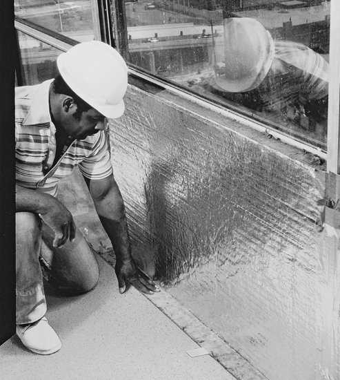
Fire requirements are concerned with the combustibility of the wall materials, the fire resistance ratings and vertical dimensions of parapets and spandrels, the fire resistance ratings of exterior walls facing other buildings that are near enough to raise questions of fire spread from one building to the other, and the closing-off (firestopping) of any vertical passages in the wall that are more than one story in height. At each floor, the space inside column covers and the space between the exterior wall system and the edges of floors must be firestopped, using mineral wool safing or other material that can restrict the passage of smoke and fire through these gaps (Figures 19.16 and 20.16). See Chapter 1 for more about fire resistance rating requirements for building exterior walls.
Figure 19.16 Safing is a high-temperature, fire-resistant mineral batt material that is inserted between a curtain wall panel and the edge of the floor slab to block the passage of fire from one floor to the next. It is seen here behind a metal-and-glass curtain wall with insulated spandrel panels. The safing is held in place by metal clips such as the one seen in the foreground. (Photo courtesy of United States Gypsum Company.)
As energy conservation codes, sustainability programs, and high-performance building standards continue to become increasingly stringent in their limits on building energy consumption, exterior wall designs continue to evolve and improve to keep step with these demands. Improvements in air barrier and insulation materials, more attention to the proper detailing of these components, improved glazing materials, and enhanced window and curtain wall framing all contribute to buildings that are more energy efficient, comfortable, and durable.
KEY TERMS
REVIEW QUESTIONS
1. Why is it so difficult to make cladding watertight?
2. List the functions that cladding performs and list one or two ways in which each of these functions is typically satisfied in a cladding design.
3. Using a series of simple sketches, explain the principles of sealant joint design. List several sealant materials suitable for use in the joints that you have shown.
4. What are the forces that can move water through a joint in an exterior wall? How can each of these forces be neutralized?
EXERCISES
1. Examine the cladding of a building with which you are familiar. Look especially for features that have to do with insulation, condensation, drainage, and movement. Sketch a detail of how this cladding is installed and how it works. You will probably have to guess at some of the hidden features, but try to produce a complete, plausible detail. Add explanatory notes to make everything clear.
2. Work out a way to add a rainscreen window with fixed double glazing to the cladding system shown in Figure 19.8.
3. Prepare a sample sealant joint, using a backer rod and silicone sealant obtained from a hardware store or building materials supplier. Apply the sealant to two parallel pieces of quarry tile or glass that are taped together with a spacer between them. After the sealant has had time to cure (a week or so), remove the tape and spacer and test the joint by pulling and twisting it to find out how elastic it is and how well the sealant has adhered to the substrate.
SELECTED REFERENCES
The Institute for Research in Construction of the National Research Council Canada has done pioneering work in theorizing about exterior wall design and performing tests and field observations to back up the theory. This work is summarized in a large library of reports on specific topics that may be viewed online at www.nrc.ca/irc/ircpubs. See, for example, the document entitled Evolution of Wall Design for Controlling Rain Penetration.
Amstock, Joseph S. Handbook of Adhesives and Sealants in Construction. New York, McGraw-Hill, 2000.
This book offers detailed information on all types of sealants, construction adhesives, joint and crack control in concrete, and firestopping, as well as the design, specification, and testing of sealant joints.
Brock, Linda. Designing the Exterior Wall: An Architectural Guide to the Vertical Envelope. Hoboken, NJ, John Wiley & Sons, Inc., 2005.
This book covers the building science underlying the performance of the exterior wall and provides examples of its application to the design of wall types ranging from light wood construction to metal curtain wall.
Brookes, Alan, and Maarten Meijs. Cladding of Buildings (4th ed.). New York, Taylor & Francis, 2008.
This book provides a clear general introduction to cladding principles and material types.
WEB SITES
Designing Exterior Wall Systems
Author's supplementary web site: www.ianosbackfill.com/19_designing_cladding_systems
Dow-Corning sealants: www.dowcorning.com
GE sealants: www.siliconeforbuilding.com
Institute for Research in Construction: www.nrc.ca/irc/ircpubs
Whole Building Design Guide—Wall Systems: www.wbdg.org/design/env_wall.php