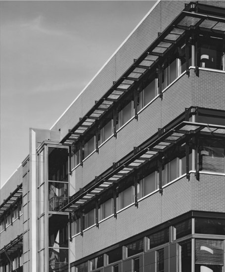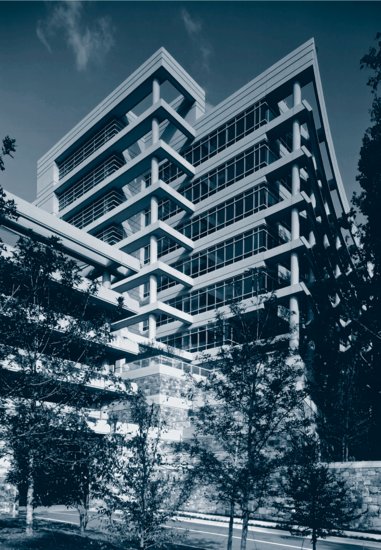
Architects Thompson Ventulett Stainback & Associates created a bold pattern of precast concrete sunshades and spandrel panels for the facades of the United Parcel Service Headquarters Building in Atlanta, Georgia. (Photo by: Brian Gassel/TVS & Assoc.)
20
CLADDING WITH MASONRY AND CONCRETE
Prefabricated Brick Panel Curtain Walls
Stone Panels Mounted on a Steel Subframe
Monolithic Stone Cladding Panels
Stone Cladding on Steel Trusses
Posttensioned Limestone Spandrel Panels
Precast Concrete Curtain Walls
Glass-Fiber-Reinforced Concrete Curtain Walls
Exterior Insulation and Finish System
Keeping Water Out with Masonry and Concrete Cladding
MASONRY VENEER CURTAIN WALLS
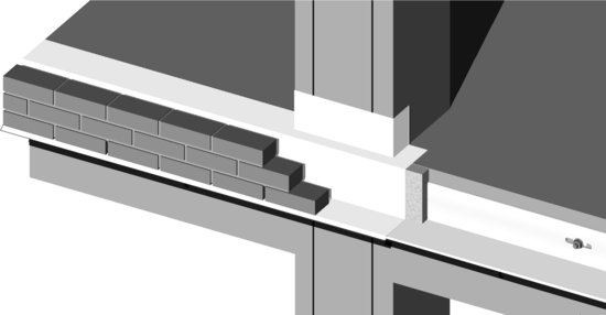
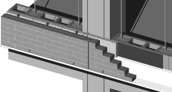
Figure 20.1 illustrates steps in the construction of brick masonry veneer cladding (a single wythe of brick masonry separated by a cavity from a backup wall) applied to a reinforced concrete frame. The veneer may also be made of stone. The veneer is erected brick by brick or stone by stone with conventional mortar, starting from a steel shelf angle that is attached to the structural frame at each floor (Figure 20.2).
Figure 20.1 Construction sequence for a brick veneer curtain wall supported by a reinforced concrete frame. (a) Before the concrete frame of the building was cast, inserts were put into the formwork to form attachments for the brick veneer, including wedge anchors along the line of each shelf angle, two vertical dovetail slots in each column, short vertical dovetail slots in the spandrel beams, and horizontal reglets in the centers of the spandrel beams to accept the inner edge of a flashing over each window head (see the Chapter 15 sidebar “Fastening to Concrete” for pictures of inserts such as these). To begin installation of the brick veneer, a steel shelf angle is bolted to the spandrel beam, using, for example, malleable iron wedge inserts as shown in Figure 20.2. A slab of polystyrene foam or mineral wool board thermal insulation (gray) is placed over the upright leg of the shelf angle, and a continuous flashing (white) is installed over the shelf angle, the insulation, and the edge of the floor slab. This flashing also wraps around the front of the column. All the seams in the flashing are overlapped and made watertight with sealant. The first course of brickwork is laid directly on the shelf angle and flashing, without a bed joint of mortar. Every third head joint is left open in this first course to form a weep hole. Three courses of brickwork bring the veneer up to the level of the floor slab. (b) The first course of the concrete masonry backup wall is laid. Vertical reinforcing bars are grouted into the hollow cores of the backup wall at intervals specified by the structural engineer. A liquid coating or adhered sheet is applied to the backup wall to act as an air and moisture barrier. Three more courses of brick veneer bring the top of the veneer up to the level of the top of the first course of concrete masonry. Additional insulation is placed against the concrete masonry. A combination joint reinforcing and masonry tie made of heavy stainless steel wires is laid on top of the masonry, tying the brick veneer to the backup wall. Plastic clips are snapped onto the tie rods of the joint reinforcing to hold the insulation in position. A vertical expansion joint in the brick veneer is provided at the centerline of each column. A heavy wire masonry tie in a dovetail slot anchors the brick veneer to the column on each side of the joint; another such anchor is lying loose on top of the bricks, ready to be installed, in this view. (c) The wall rises in vertical increments of 16 inches (400 mm), which equals six courses of brick or two of concrete masonry. This is also the vertical distance between ties and the height of the insulating panels. A-blocks (see Figure 9.23) are utilized as needed in the backup wall to avoid having to thread blocks over the tops of the vertical reinforcing bars. The vertical expansion joint is sealed with backer rod and sealant. As an alternative to the sequence of operations illustrated here, the backup wall and air barrier may be installed to their full height first, followed later by the installation of insulation and veneer.

(a)
(b)
(c)
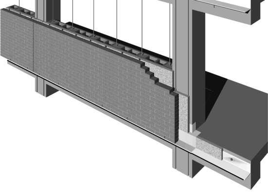
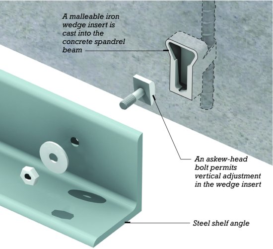
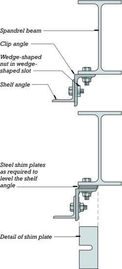
Figure 20.2 (a) An example of a cast-in-place anchoring system for attaching a steel shelf angle to a concrete spandrel beam. Steel shims are added as necessary between the shelf angle and the spandrel beam to place the angle exactly in the plane of the veneer wythe. (b) The traditional method for attaching shelf angles to steel spandrel beams uses steel clip angles with shim plates as needed to make up for dimensional inaccuracies in the components. In practice, providing anchoring systems with adequate adjustability to account for deviations in the structural frame is often a difficult challenge.
(a)
(b)
Many steps in the process and details of the assembly are essentially the same as for a masonry cavity wall of a single-story building, but there are some crucial differences: To prevent normal movements in the frame of the building or expansion and contraction in the masonry veneer from causing stress in the veneer, the veneer is divided into rectangular panels of reasonable size surrounded by expansion joints that can absorb these movements. At each floor level, a horizontal expansion joint (soft joint) is provided beneath the shelf angle (Figure 20.3). This joint is made wide enough to absorb the sum of column creep, brick expansion, spandrel beam deflection, and tolerances for construction inaccuracies while not exceeding the safe movement capacity of the sealant. Similarly, vertical expansion joints protect the veneer from stresses caused by movements in the horizontal plane (Figure 20.4).
Figure 20.3 A complete detail section of the brick veneer wall that was begun in Figure 20.1 shows how the top of the backup wall is fastened to the underside of the spandrel beam with a series of steel restraint clips that brace the top of the wall against wind loads but allow the spandrel beam to deflect under load. This joint is sealed with two lines of backer rod and sealant. A soft joint of sealant beneath the shelf angle permits the spandrel beam to deflect without applying force to the brick veneer. The brick ties nearest the underside of the shelf angle are anchored to dovetail slots in the spandrel beam. An additional plastic clip on each wire tie in the center of the cavity acts as a drip to prevent water from clinging to the tie and running toward the backup wall. The interior of the building is finished with gypsum veneer plaster mounted on steel furring channels, similar to the assembly shown in Figure 23.4. You can download a PDF of this figure at http://www.wiley.com/go/aflblce6ne.
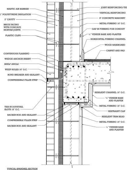
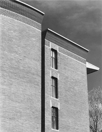
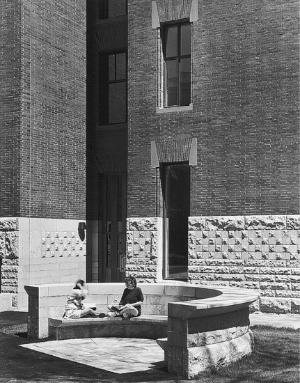
Figure 20.4 (a) A carefully detailed brick curtain wall by architects Kallman, McKinnell and Wood covers the steel frame of Hauser Hall at Harvard University. Notice the vertical expansion joint near the far-right corner. (b) At the base of Hauser Hall, the facing wythe is made of limestone blocks. The backup wall consists of steel studs and gypsum sheathing panels. A vertical expansion joint is visible in the far-left corner in this view. (Photos © Steve Rosenthal.)
(a)
(b)
Stone and brick veneer cladding may also be constructed with a backup wall constructed of light gauge steel studs covered with water-resistant sheathing panels of gypsum or cementitious materials (Figure 20.5). In comparison to concrete masonry, stud-framed backup walls are lighter in weight, faster to erect, easier to insulate, more accommodating of electrical wiring, and readily covered with a great variety of interior finish materials. However, a steel stud framed wall is more flexible than one made of concrete masonry and prone to greater deflections under the pressures of the wind. If these deflections are too great, mortar joints in the masonry veneer begin to crack, and water leakage through the veneer increases. This in turn can subject the gypsum sheathing panels to moisture deterioration and the steel studs and fasteners to corrosion. In contrast, a concrete masonry backup wall is easily made stiffer than the veneer that it supports, greatly reducing the risk of wind load stresses on the veneer. A concrete masonry backup wall can also, if necessary, sustain prolonged periods of wetting with less risk of deterioration.
Figure 20.5 A detail section of a brick curtain wall. The veneer is supported on a shelf angle suspended below the level of the spandrel beam on a frame also made of steel angles. The supporting frame becomes necessary when continuous horizontal bands of windows are to be installed between brick spandrels. All its connections are made with bolts in slotted holes to allow alignment of the shelf angle. After the frame has been aligned and before the masonry work begins, the connections are welded to prevent slippage. Continuous insulation applied to the outside of the metal stud framed backup wall minimizes energy losses from thermal bridging through the metal framing components.

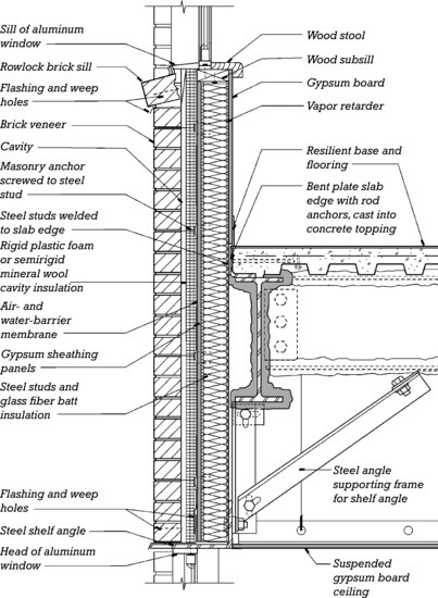
For these reasons, where steel stud backup systems are selected, the metal framing, masonry ties, and fasteners should be sized conservatively to ensure that the completed system is stiff enough to protect the veneer from wind load stresses. The sheathing material, anchors, and fasteners should be selected for their durability under damp conditions. Each metal tie that connects the masonry veneer to the studs should be attached to a stud with at least two corrosion-resistant screws. The wall must be detailed carefully to keep leaked water away from the backup components. Inspection should be required during construction to ensure that all these details are faithfully executed and the cavity is kept clean so that it will drain freely.
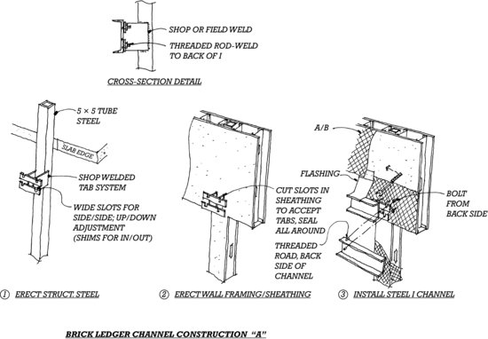
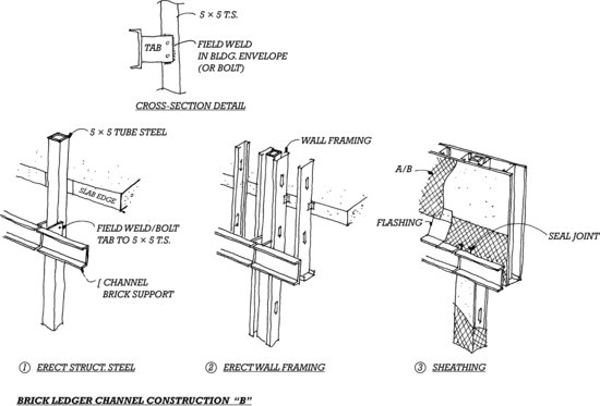
The structural frame of a building is never absolutely flat or plumb. Thus, the system for attaching shelf angles must allow adjustment, so that the veneer may be constructed in a more precisely vertical plane with level courses. Figure 20.2 illustrates examples of how this is accomplished with both concrete and steel frames. The attachment system shown in Figures 20.5 and 20.6, which is designed to suspend a masonry veneer spandrel wall over a continuous band of windows, also provides for free adjustment of the shelf angle location.
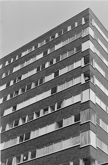
Figure 20.6 The section shown in Figure 20.5 allows the construction of brick spandrels between continuous horizontal bands of glass. (Photo by Edward Allen.)
The flashing above the shelf angle plays an important role in capturing water that reaches the cavity and conducting it back out of the wall. This flashing runs continuously over the shelf angle and should project beyond the face of the veneer sufficiently to form an effective drip. If a flexible flashing material is used, it should be cemented to a strip of sheet metal, with the sheet metal projecting from the wall. Efforts to hide this important flashing should be approached with caution. Terminating the flashing at the edge of, or even slightly behind, the face of the veneer invites water to be drawn under the flashing by capillary action. Water that gets behind the flashing can corrode the shelf angle and its fastenings; in cold climates, it also invites freeze-thaw of the masonry veneer. Over time, damage to the shelf angle or its supports can cause unsightliness, and if more severe, imperil the stability of the veneer itself.
Prefabricated Brick Panel Curtain Walls
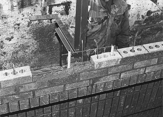
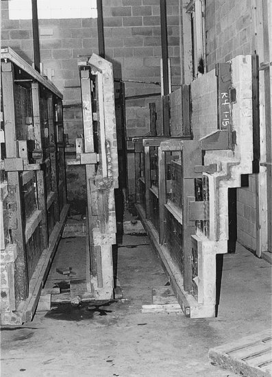
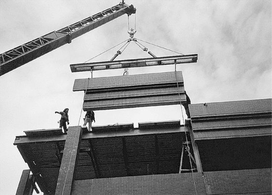
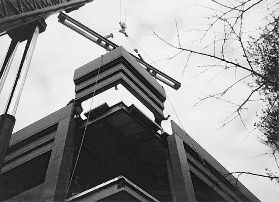
Figure 20.7 shows the use of prefabricated reinforced brick panels for cladding. Masons construct the panels while working comfortably at ground level in a dry, climate-controlled factory or shop. Horizontal reinforcing may be laid into the mortar joints or grouted into channel-shaped bricks. Vertical reinforcing bars are placed in grouted cavities of hollow-core bricks. These panels are self-rigid; they need no structural backup and can be fastened to the building in much the same way as precast concrete panels. A steel stud backup wall is required to carry thermal insulation, air barrier, electrical wiring, and an interior finish layer, but it has no structural role.
Figure 20.7 Fabrication and installation of a brick panel curtain wall. (a) Masons construct the panels in a factory, using conventional bricks and mortar. Both horizontal and vertical reinforcing are used, the vertical bars being grouted into the hollow cores of the bricks. (b) Brick panels are stored to await shipment, complete with thermal insulation attached to the back of the panels. The welded metal brackets are for attachment to the building; the structural strength of the panel comes primarily from the reinforced masonry, not the brackets. (c) At the construction site, panels are lifted into position by crane. (d) Corners can be constructed as single panels. (Panelized masonry by Vet-O-Vitz Masonry Systems, Inc., Brunswick, Ohio.)
(a)
(b)
(c)
(d)
STONE CURTAIN WALLS
Chapter 9 discusses types of stone and illustrates conventionally set stone facing systems that tie relatively small blocks of cut stone to a concrete masonry backup wall. Slabs of stone that are larger in surface area may be fastened to framed buildings in several different ways.
Stone Panels Mounted on a Steel Subframe
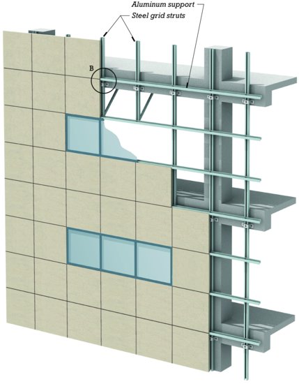
Figure 20.8 shows a system for mounting stone panels on a steel subframe, called grid-system-supported stone cladding. The vertical members of the subframe are erected first. They are designed to transmit gravity and wind loads from the stone slabs to the frame of the building. The horizontal members are aluminum shapes that engage slots in the upper and lower edges of each panel to attach them firmly to the building. They are added as the installation of the stone panels progresses. Backer rods and sealant fill the spaces between the panels, allowing for necessary movement. A nonstructural backup wall, usually made of steel studs and gypsum sheathing panels, is constructed within the frame of the building but is not attached to the subframe. Its functions are to provide an air barrier, to house thermal insulation batts and electrical wiring, and to support the interior wall finish layer, which is usually plaster or gypsum board.
Figure 20.8 (Top) A subframe of vertical steel struts supports a facing of stone panels by means of horizontal metal clips that engage slots in the upper and lower edges of the panels. To avoid corrosion and staining problems, the steel struts should be galvanized, and the clips should be made of a nonferrous metal (aluminum or stainless steel) that is chemically compatible with the type of stone being used. (Bottom) A detail of the support-to-panel connection.
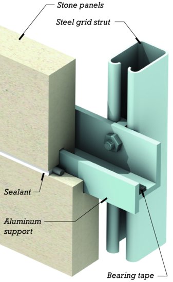
A weakness of this system is its dependence on the integrity of the sealant joints. If leakage occurs, water may accumulate in the slots in the tops of the stone panels, and freeze-thaw deterioration may risk damage to the relatively fragile, narrow tongues of stone on either side of the groove.
Monolithic Stone Cladding Panels
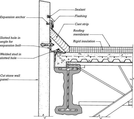
Figures 20.9 and 20.10 illustrate the use of monolithic stone cladding panels that are fastened directly to the frame of the building. The weight of each panel is transferred to two steel support plates by means of edge pockets that are cut into both sides of each panel at the stone mill. Each panel is stabilized by a pair of steel angle struts that are bolted to the stone with expansion anchors in drilled holes. Joints are closed with backer rod and sealant, and a nonstructural backup wall is required.
Figure 20.9 (a) Parapet and (b) spandrel details for a stone panel curtain wall made of limestone, marble, or granite. The broken lines indicate the outline of the interior finish and thermal insulation components, which are not shown. Each support plate holds edges of two adjacent wall panels, which are pocketed as shown to rest on the plate. The plate should be made of a noncorroding metal. The vertical joints between panels are closed with a backer rod and sealant.
(a)
(b)
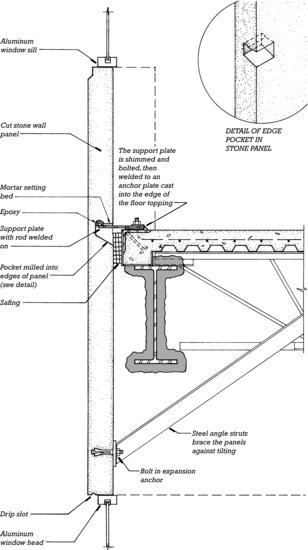
Figure 20.10 A granite panel curtain wall of the type illustrated in Figure 20.9 wraps around the corner of a Boston office building. The upper-floor windows have not yet been installed, but the window frames have been mounted in two of the middle floors, and the lower floors have been glazed.

Stone Cladding on Steel Trusses
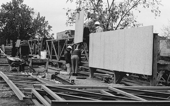
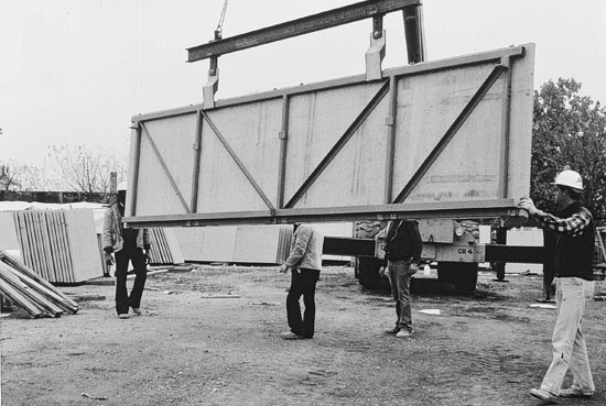
In truss-supported stone cladding, sheets of stone are combined into large prefabricated panels by mounting them on steel trusses (Figure 20.11). Each truss is designed to carry both wind loads and the dead load of the stone to connection brackets that transfer these loads to the frame of the building. Sealant joints and a nonstructural backup wall finish the installation.
Figure 20.11 A steel truss system for stone cladding. (a) Masons working in a fabrication yard attach thin sheets of stone to welded steel trusses. The vertical joints are closed with backer rods and sealant. (b) The fabricated spandrel panel is lifted onto a truck using a crane. The metal clips that are just visible along the top and bottom edges of the panel engage slots in the edges of the sheets of stone to hold the stone securely to the truss. The steel angle clips at the two upper corners of the truss will support the panel on brackets welded to the steel columns of the building frame. (c) The panel is installed. (Courtesy of International Masonry Institute, Washington, D.C.)
(a)
(b)
(c)
Posttensioned Limestone Spandrel Panels
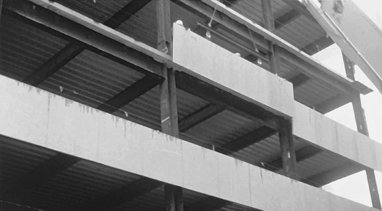
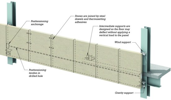
Thick blocks of limestone may be joined with adhesives into long spandrel panels and posttensioned with high-strength steel tendons so that the assembly is self-supporting between columns (Figure 20.12). Such posttensioned limestone spandrel panels are relatively costly, because of their use of comparatively large quantities of stone per unit area of cladding.
Figure 20.12 Thicker blocks of Indiana limestone may be posttensioned together to make spandrel panels that span from column to column but require little steel. The posttensioning tendon is threaded through matching holes that are drilled in the individual stones prior to assembly.
Very Thin Stone Facings
Extremely thin sheets of stone (as thin as ¼ inch, or 6.5 mm, for granite) may be stiffened with a structural backing such as a metal honeycomb and mounted as spandrel panels in an aluminum mullion system such as those described in Chapter 21.
Very thin sheets of stone may also be used as facings for precast concrete curtain wall panels. The stone sheets are laid face down in the forms. Stainless steel clips are inserted into holes drilled in the backs of the stone. A grid of steel reinforcing bars is added, and then the concrete is poured and cured to complete the panel. The clips anchor the stone to the concrete.
When specifying the thickness of stone for any exterior cladding application, the designer should work closely with the stone supplier and also consult the relevant standards of the building stone industry. Stone that has been sliced thinner than industry standards has caused a number of failures of cladding systems.
PRECAST CONCRETE CURTAIN WALLS
Precast concrete cladding panels, both conventionally reinforced and prestressed (this chapter's opening photograph and Figures 20.13–20.16), are simple in concept but require close attention to matters of surface finish, mold design, thermal insulation, attachment to the building frame, and sufficient strength and rigidity in the building frame to support the weight of the panels.
Figure 20.13 A typical detail of a precast concrete curtain wall on a sitecast concrete frame. Panels in this example are a full story high, each containing a fixed window. The reinforcing has been omitted from the panel for the sake of clarity, and the outline of the thermal insulation and interior finishes, which are not shown, is indicated by the broken lines.
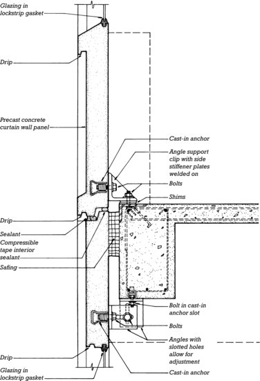
Figure 20.14 Workers install a precast concrete curtain wall panel. (Architects and engineers: Ander-Nichols Company, Inc. Photo by Edward Allen.)
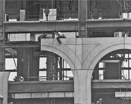
Figure 20.15 A Chicago hotel is clad in precast concrete panels. (Photo by Hedrich Blessing, Ltd.)

Figure 20.16 (Top) Precast concrete panels and aluminum windows being installed on a concrete frame. (Bottom) A close-up view of the panel installation. The back of the panel is insulated with polyisocyanurate plastic foam insulation. At the edge of the concrete floor slab, safing (to protect against fire easily passing from one floor level to the next) seals the gap between the slab edge and the back of the panel. The metal plate welded to the face of the column will support a future metal canopy. (Photo by Joseph Iano.)
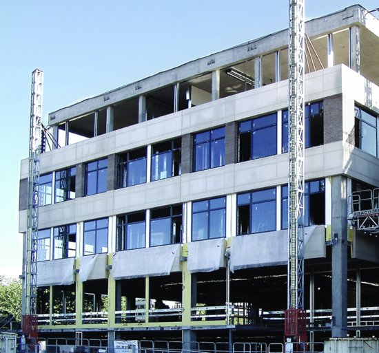
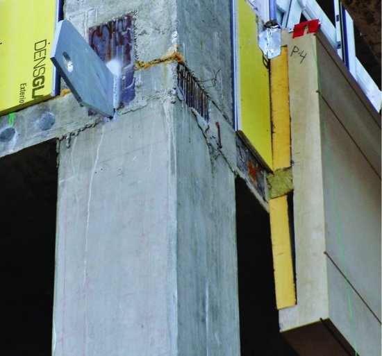
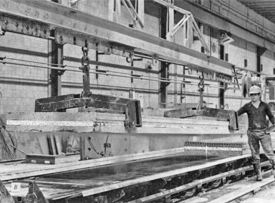
The factory production of concrete cladding panels makes it possible to utilize high-quality molds and a variety of surface finishes, from glassy smooth to rough, exposed aggregates. Ceramic tiles, thin bricks, or thin stone facings may be attached to precast concrete panels. In precast concrete sandwich panels, thermal insulation is incorporated as an inner layer of the panel (Figures 20.17 and 20.18). Alternatively, insulation may be affixed to the back of the panel or may be provided in a nonstructural backup wall that is constructed in place. Reinforcing or prestressing of the panel must be designed to resist wind, gravity, seismic, and lifting forces and control cracking of the concrete. Attachments must transfer all these forces to the building frame while allowing for installation adjustment and for relative movements of the frame and the cladding.
Figure 20.17 Manufacturing a Corewall® insulated panel, a proprietary foam-core precast concrete sandwich panel. Rollers apply a ribbed texture to the outside of a panel that includes a layer of foam plastic insulation sandwiched between layers of concrete. (Photos reproduced with permission of COREWALL LIMITED.)
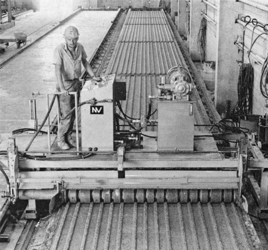
Figure 20.18 A completed panel is lifted from the casting bed. (Photos reproduced with permission of COREWALL LIMITED.)
More recently developed materials, such as carbon fiber reinforcing (Chapter 15) or ultra-high-performance concrete (Chapter 13), allow the manufacture of panels that are thinner and lighter than those made of conventional materials.
Glass-Fiber-Reinforced Concrete Curtain Walls
Glass-fiber-reinforced concrete (GFRC) is a relatively new cladding material that has several advantages over conventional precast concrete panels. Its admixture of short glass fibers furnishes enough tensile strength that no steel reinforcing is required. Panel thicknesses and weights are about one-quarter of those for conventional precast concrete panels, which saves money on shipping, makes the panels easier to handle, and allows the use of lighter attachment hardware. The light weight of the cladding also allows the loadbearing frame of the building to be lighter and less expensive. GFRC can be molded into three-dimensional forms with intricate detail and an extensive range of colors and textures (Figures 20.19 and 20.20).
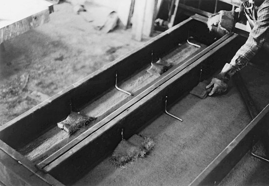
Figure 20.19 Fabrication of a GFRC wall panel. (a) Concrete and chopped glass fibers are sprayed into a mold and compacted with a hand roller to create a panel facing. Only the top half of the facing has been applied to the mold in this illustration. (b) A welded frame of steel studs with L-shaped steel rod anchors is lowered onto the back of the facing and held just above it by spacers. Pads of GFRC are placed over the anchors by hand to join the facing to the frame. (c) After overnight curing, the completed panel is removed from the mold and stored for further curing before installation.
(a)
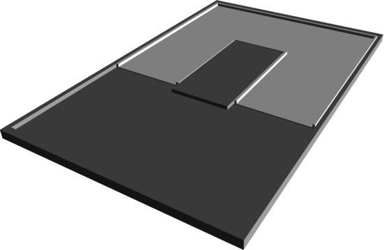
(b)
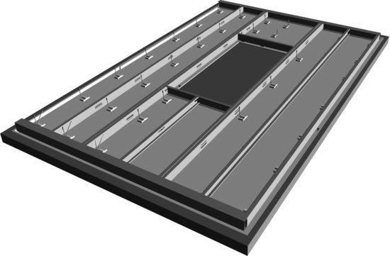
(c)
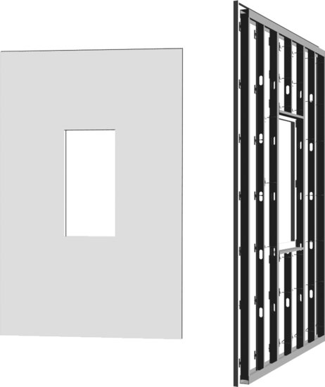
Figure 20.20 Fabrication of a GFRC curtain wall panel. (a) A special gun deposits a layer of sand–cement slurry simultaneously with 1.5-inch (38-mm) lengths of alkali-resistant glass fiber reinforcing. Three layers are usually required to make up the full thickness of the panel facing; each is compacted with a small hand roller before the next layer is applied. The overall thickness is usually ½ inch (13 mm). (b) After the GFRC facing layer has been completed, the steel frame is lowered over it and the operator hand-applies pads of wet GFRC over the rod anchors to bond the frame to the GFRC facing. (Courtesy of Precast/Prestressed Concrete Institute.)
(a)
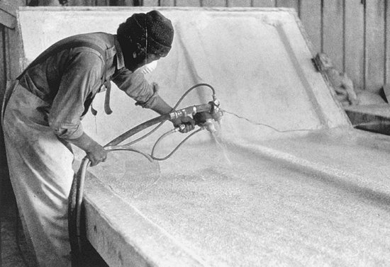
(b)
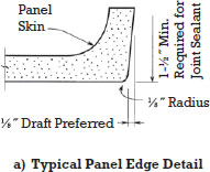
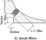
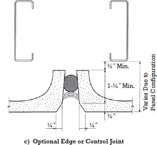
The fibers in GFRC must be manufactured from a special alkali-resistant type of glass to prevent their disintegration in the concrete. The panels may be self-stiffened with GFRC ribs, but the usual practice is to attach a welded frame made of light gauge steel studs to the back of each GFRC facing in the factory. The attachment is made by means of thin steel rod anchors that flex slightly as needed to permit small amounts of relative movement between the facing and the frame. Figure 20.21 shows typical ways of attaching metal-framed GFRC panels to the building. The edges of the GFRC facing, which is usually only about ½ inch (13 mm) thick, are flanged as shown in Figure 20.22 so that backer rods and sealant may be inserted between panels.
Figure 20.21 Typical connections of GFRC panels to a steel building frame. The lower connection in each case is a threaded rod that can flex as necessary as the height of the upper connection is adjusted with shims. (Courtesy of Precast/Prestressed Concrete Institute.)

Figure 20.22 Typical edge details for GFRC cladding panels. (Courtesy of Precast/Prestressed Concrete Institute.)
EXTERIOR INSULATION AND FINISH SYSTEM
An exterior insulation and finish system (EIFS) consists of a layer of plastic foam insulation that is adhered or mechanically fastened to a backup substrate, a reinforcing mesh that is applied to the outer surface of the foam by embedment in a base coat of a stuccolike material, and an exterior finish coat of a similar material that is troweled over the reinforced base coat. In most cases the substrate is concrete masonry or site-erected steel studs covered with water-resistant sheathing (Figures 20.23 and 20.24). The system also adapts readily to prefabrication (Figure 20.25).
Figure 20.23 Four steps in installing an EIFS over a building with walls of masonry or solid sheathing. (A) A panel of foam is daubed with polymer-modified portland cement mortar. The foam may be as thick as required to achieve the desired thermal performance. (B) The foam panel is pressed into place, where it is held permanently by the adhesive mortar. (C) A thin base coat of polymer-modified stucco is applied to the surface of the foam panels, with an embedded mesh of glass fiber to act as reinforcing. (D) After the base coat has hardened, a finish coat in any desired color is troweled on. (Used by permission of Dryvit® System, Inc.)
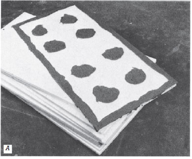
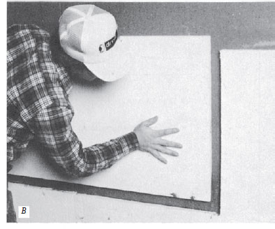
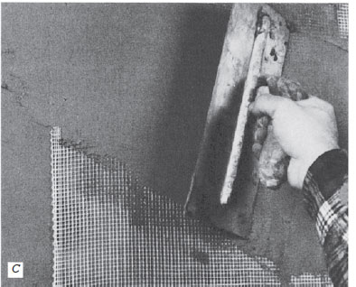
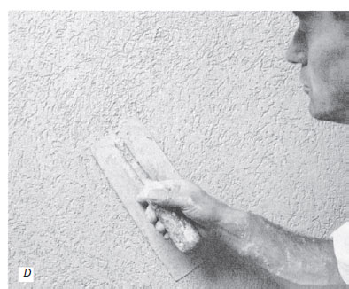
Figure 20.24 An early 20th-century warehouse, reclad with EIFS to improve its energy efficiency and renew its appearance. (Photo by Joseph Iano.)
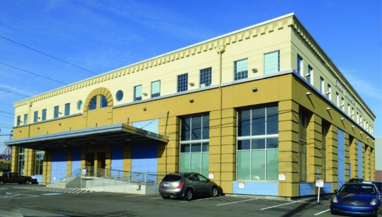
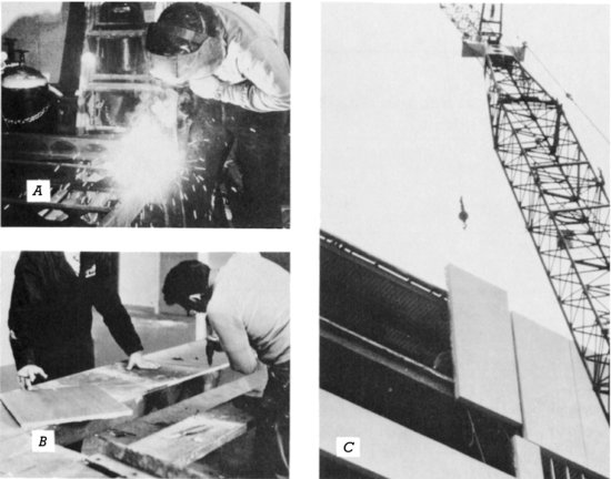
Figure 20.25 EIFS cladding can be shop-fabricated and erected in panel form. (A) Steel studs are welded together to make panel frames. (B) Rigid sheathing is screwed to the panel frames and finished with EIFS as shown in Figure 20.23. (C) The finished panels are bolted to the frame of the building. (Photo: John Bare. Used by permission of Dryvit® System, Inc.)
EIFS is an unusually versatile type of cladding, used for building types as diverse as single-family residences of wood or masonry construction as well as the largest buildings of noncombustible construction. It is used both for new construction and for refacing and insulating existing buildings. The insulating foam layer may be up to 4 inches (100 mm) thick, and there is little or no thermal bridging. The finish layer may be applied in a range of colors and textures. In appearance, at least from a distance, EIFS is virtually indistinguishable from conventional stucco.
Two types of EIFS can be distinguished by differences in insulation and coating materials. Polymer-based or Class PB EIFS most frequently uses a low-density expanded polystyrene bead foam insulation, a glass fiber reinforcing mesh embedded in a base coat that is formulated primarily from either portland cement or acrylic polymer, and a finish coat that consists of texture granules in an acrylic polymer vehicle. The foam insulation is usually adhered to the backup wall, although in some cases it may be mechanically attached. Polymer-modified or Class PM EIFS uses a slightly higher density, extruded polystyrene foam insulation rather than expanded bead foam. The foam panels are mechanically attached to the backup wall with metal or plastic screws (plastic screws minimize thermal bridging through the insulation). A metal reinforcing mesh is embedded in a relatively thick portland cement base coat, and the finish coat is formulated of portland cement with acrylic modifiers. Class PM EIFS is also sometimes referred to as hard coat EIFS.
In North America, Class PB is the most commonly specified type of EIFS. The relatively thin coating is elastic and resistant to cracking. However, this type is also the most vulnerable to dents or puncture when applied to areas of a building that may come in contact with passersby or vehicles. Class PM EIFS is more durable (and more expensive) than polymer-based systems. It is more susceptible to shrinkage cracking during curing, but also more resistant to physical abuse.
In the past, EIFS has at times proven vulnerable to water intrusion, leading, in some cases, to costly failures of the building enclosure. In response, materials and installation methods have evolved. For example, where paper-faced gypsum panels were once used as the system substrate, today more durable, moisture-resistant panel types, such as glass mat faced gypsum sheathing, are used. To prevent sealant joints around the edges of the panels from peeling away the EIFS finish coat, sealant is now installed against the base coat of the system before the finish coat is applied. Careful attention is given to sealant material selection and joint design, to limit the forces exerted on the base coat by the sealant.
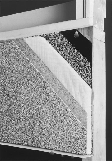
Additionally, EIFS installations have evolved two approaches to the control of moisture penetration. Barrier-wall EIFS relies solely on the coating layers and joint sealants between panels to protect against water penetration. Drainage-wall or water-managed EIFS creates a drainage plane between the insulation and substrate to which it is attached, allowing water that does penetrate to flow downward and back out through weeps provided at the base of each panel. The drainage plane consists of a water-resistant membrane applied over the substrate and a thin space between this layer and the insulation. The most common way to create the drainage space is by applying the insulation adhesive in vertical strips, with the gaps remaining in between acting as drainage channels. Alternatively, insulation boards with integral vertical channels may be used, or a thin, pervious drain mat may be installed between the insulation and substrate (Figure 20.26).
Figure 20.26 A mockup demonstrates the features of a water-managed EIFS system. From interior to exterior, the layers are a water-resistant substrate board, an asphalt-saturated felt air and moisture barrier, a drainage mat composed of plastic fibers, plastic foam insulation, reinforcing mesh, a base coat, and a finish coat. A continuous plastic flashing under a gap at the bottom of the wall drains any leakage out to the face of the wall. Fluid-applied or adhered sheet membranes that can act as air and moisture barriers are also frequently used in place of the building felt shown here. (Photograph of Senergy CD System, courtesy of Senergy, Cranston, RI.)
Class PB EIFS is installed to meet the performance requirements of ASTM E 2568. The International Building Code requires water-managed EIFS where applied over light wood frame buildings of any residential occupancy type. Careful supervision of EIFS during its installation is also required, to ensure that proper installation methods are followed and the necessary workmanship standards are maintained.
KEEPING WATER OUT WITH MASONRY AND CONCRETE CLADDING
The choice of barrier wall or rainscreen design for watertightness (strategies described in Chapter 19) varies with the characteristics of the cladding system. For example, brick masonry veneer is best suited to rainscreen design. The large area of mortar joints within the wall surface tends to make the veneer layer leaky, especially as it ages. For this reason, brick veneer cladding is designed with an internal drainage plane that intercepts water that penetrates the masonry and redirects the water back to the exterior (Figure 20.2). Stone cladding systems made up of relatively small stone units, individually installed in the field, also typically rely on rainscreen design.
On the other hand, precast concrete cladding often relies, in large part, on a barrier wall strategy. The panels themselves are manufactured in factory-controlled conditions, using high-quality ingredients and methods of fabrication. The result is a panel that is durable, is highly resistant to water penetration, and does not necessarily benefit from the addition of a secondary drainage plane behind the panel (Figures 20.9 and 20.16). However, where panels meet, and joints must be sealed in the field, a two-stage joint that does incorporate rainscreen principles is more likely to remain reliably watertight over the life of the cladding than a simple surface-sealed joint.
Considerations of constructability also play a role in the choice of design for watertightness with the cladding systems discussed in this chapter. When large, prefabricated panels are installed from the exterior side of the building, the relatively intricate flashing and drainage systems that are part of rainscreen systems may become difficult or impractical to achieve, and barrier wall design may be the more economical and practical solution.
KEY TERMS
REVIEW QUESTIONS
1. List all the common ways of attaching stone cladding to a building. Make a simple sketch to explain each system.
2. Working from memory, sketch all the details of a brick veneer wall over a concrete frame.
3. What are some options of surface finishes for precast concrete cladding panels?
4. Describe the process of producing GFRC panels, illustrating your account with simple sketches.
5. Name two types of EIFS. Describe two ways of applying EIFS to a building. Why should barrier wall EIFS be avoided?
EXERCISES
1. Design and detail a brick veneer cladding for a multistory building that you are designing. Rather than trying to conceal the flashings and soft joints, work out a way of expressing them boldly as part of the architecture of the building.
2. Visit one or more buildings under construction that are being clad with masonry, concrete, GFRC, or EIFS. Make sketches of how the materials are detailed, especially how they are anchored to the building. What will happen to any water that leaks through the cladding?
3. Adapt the brick veneer details in this chapter to installation on a building framed with structural steel.
SELECTED REFERENCES
All the references on stone and concrete masonry listed at the end of Chapter 9 are also relevant to this chapter.
Brick Industry Association. Technical Notes on Brick Construction, Nos. 18, 18A, 21, 21A, 21B, 21C, 27, 28B. Reston, VA, Author, various dates.
These detailed pamphlets cover every aspect of brick veneer cladding systems.
Precast/Prestressed Concrete Institute. Architectural Precast Concrete (3rd ed.). Chicago, Author, 2007.
This is a well-illustrated hardbound book that covers all aspects of the design, manufacture, and installation of precast concrete curtain walls. Also available from the same source is Architectural Precast Concrete—Color and Texture Selection Guide (2003), an extensive set of full-color plates of finishes for precast concrete panels.
Precast/Prestressed Concrete Institute. GFRC: Recommended Practice for Glass Fiber Reinforced Concrete Panels (4th ed.). Chicago, Author, 2001.
This 104-page booklet is a clear, complete guide to the design and manufacture of GFRC cladding systems.
WEB SITES
Cladding with Masonry and Concrete
Author's supplementary web site: www.ianosbackfill.com/20_cladding_with_masonry_and_concrete
Brick Industry Association: www.gobrick.com/
Dry-Vit Systems: www.dryvit.com
EIFS Industry Members Association: www.eima.com
Precast/Prestressed Concrete Institute: www.pci.org
Whole Building Design Guide, Wall Systems: www.wbdg.org/design/env_wall.php
Figure A Seattle University School of Law.
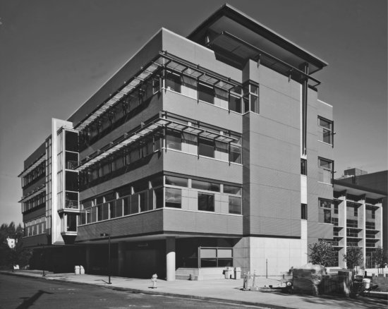
Figure C Construction drawing set detail.
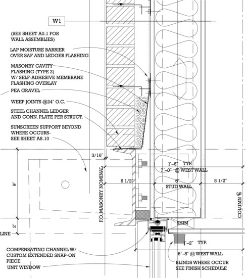
Figure D Photo detail of veneer and channel support.
