21
CLADDING WITH METAL AND GLASS
Other Curtain Wall Frame Materials
Aluminum and Glass Framing Systems
Outside Glazing and Inside Glazing
An Outside Glazed Curtain Wall System
An Inside Glazed Curtain Wall System
The Rainscreen Principle in Metal-and-Glass Curtain Walls
Expansion Joints in Metal-and-Glass Walls
The Curtain Wall Design and Construction Process
ALUMINUM EXTRUSIONS
Aluminum is the metal of choice for metal cladding systems for three primary reasons: It protects itself against corrosion. It accepts and holds a variety of attractive surface finishes. It can be fabricated economically into elaborately detailed shapes by means of the process of extrusion.
The principle of extrusion is easily visualized: It is like squeezing toothpaste from a tube. In response to the squeezing pressure, the tube extrudes a column of toothpaste that is cylindrical in shape because the orifice of the tube is round. If the shape of the orifice were changed, one could produce many other shapes of toothpaste as well—square, triangular, flat, and so on.
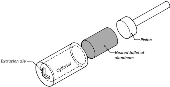
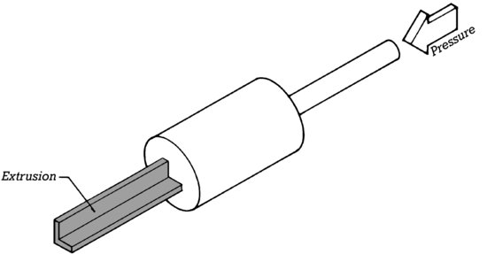
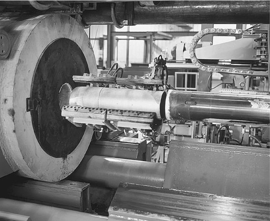
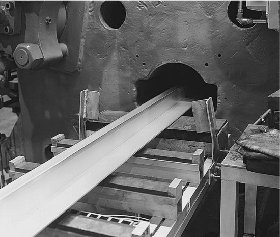
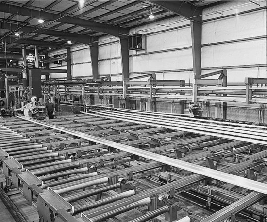
To manufacture an aluminum extrusion, a large cylindrical billet of aluminum is heated to a temperature at which the metal flows under pressure but still retains its shape when the pressure is released. The heated billet is placed in the cylinder of a large press where a piston squeezes it under enormous pressure through a die, a steel plate with a shaped metal orifice. The orifice imparts its shape to a long extruded column of aluminum that is supported on rollers, cooled, straightened as necessary, and cut into convenient lengths (Figures 21.1, 21.2).
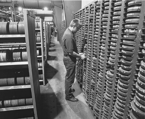
Figure 21.2 Making aluminum extrusions for curtain wall components. (a) Hundreds of extrusion dies for the many components of curtain walls are organized in racks. (b) A heated billet of aluminum is inserted into the cylinder of the extrusion press. (c) An extrusion emerges from the die. (d) Long aluminum extrusions cool on rollers, ready for straightening and cutting to length. (Photographs courtesy of Kawneer Company, Inc.)
(a)
(b)
(c)
(d)
Very intricate aluminum sections can be extruded for a variety of purposes, including not only curtain wall components but also door frames, window frames, entrances and storefronts, handrails, grillwork, and structural shapes such as wide flanges, channels, and angles. The high precision of the extrusion process permits it to be used for close-tolerance details such as snap-in glazing beads, snap-on mullion covers, screw slots, and screw ports (Figures 21.3–21.6). Hollow shapes may be extruded by mounting the portion of the die that forms the interior of the shape on a steel “spider” that is attached to the inside of the die. The metal flows around the legs of the spider before it passes through the orifice. The accompanying illustrations show some of the ways in which extruded aluminum details are utilized in building cladding. Extrusion dies are easily produced for custom-designed sections if the production run will be long enough to amortize their expense.
Figure 21.3 Screw ports are extruded cylindrical features that allow a screw to be driven parallel to the long axis of an extrusion. In the upper example, the screws pass through slightly oversized holes drilled through one box-shaped extrusion into screw ports in another box-shaped extrusion that are slightly smaller in diameter than the screws, thus engaging the screw threads tightly in the screw ports and making a snug joint. In the lower example, the screw ports are slightly larger than the outside diameter of the screws. The screws pass through the ports in a short piece of aluminum known as a “shear block” and engage slightly undersized holes in the vertical extrusion. Then the horizontal member is slipped over the shear block and screwed to it through drilled holes.
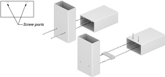
Figure 21.4 Self-tapping screws are driven through screw ports to fasten an extruded aluminum shear block to a vertical mullion. (Courtesy of Kawneer Company, Inc.)
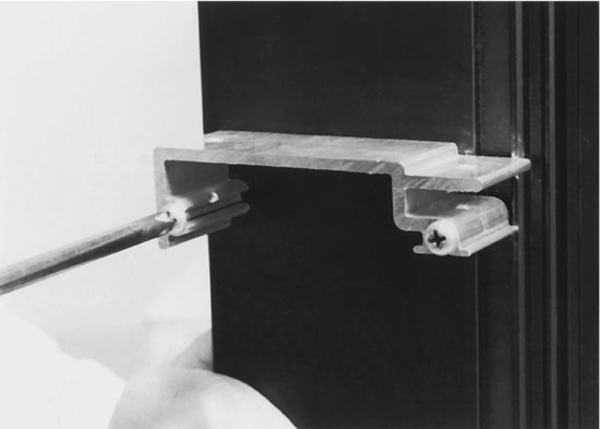
Figure 21.5 Screw slots allow screws to be driven perpendicular to the long axis of an extrusion. In this example, screws pass through oversized holes in an extruded aluminum pressure plate and pull the plate down toward the screw slot. Extruded gaskets of synthetic rubber are pressed into channels in both extrusions to seal tightly against the glass.
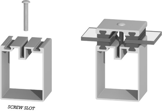
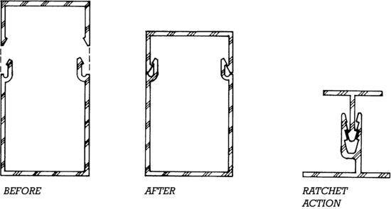
Figure 21.6 Snap-on and snap-together features are commonly used in extruded aluminum curtain wall components. Assembly is accomplished simply by aligning the components and tapping firmly with a rubber mallet or squeezing with a rubber-cushioned clamp.
Thermal Breaks
Aluminum conducts heat rapidly. In very cold weather, the indoor surfaces of an aluminum member that passes from the outside of the building to the inside, such as a window frame, would be so cold that moisture and possibly frost would condense on them. In very hot, humid weather, in an air-conditioned building, the outdoor surfaces of the same window frame might be cool enough to condense moisture from the air. This is why all but the simplest aluminum framing systems are manufactured with thermal breaks, which are internal components of insulating material that isolate the aluminum on the interior side of the component from aluminum on the exterior side. These dramatically reduce the flow of heat through the member (Figures 21.7 and 21.8).
Figure 21.7 This thermally broken aluminum mullion extrusion is sitting on a block of dry ice in a humid room. Frost has formed on the portion of the mullion nearest the dry ice, but the thermal break keeps the rest of the mullion warm enough that moisture does not condense on it. (Photo courtesy of the H.B. Fuller Company, St. Paul, Minnesota.)
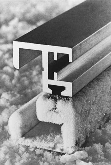
Figure 21.8 Thermal breaks in this aluminum window frame system are made from extruded polyamide plastic strips locked into preformed slots in the aluminum extrusions. The space between the thermal break strips is filled with plastic foam or mineral fiber insulation. (Photo by Joseph Iano.)
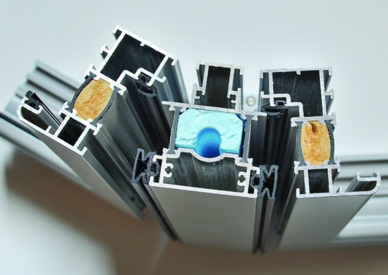
There are several ways of creating thermal breaks. Figure 21.7 shows a cast and debridged thermal break, in which molten plastic is poured into a deep channel in the center of an aluminum member, where it hardens. Then the aluminum that forms the bottom of the channel is cut away in a debridging process that leaves only the plastic to connect the two halves of the member. In Figure 21.8, thermal breaks are created with preformed polyamide thermal strips that are mechanically inserted into the aluminum extrusions during extrusion manufacture. The hollow space between the strips is filled with insulation material. Polyamide strip thermal breaks are more thermally efficient than cast and debridged beaks. Other thermal break configurations from rubber or plastic gaskets, plastic strips, and plastic clips are illustrated by examples elsewhere in this chapter.
- The ore from which aluminum is refined, bauxite, is finite but relatively plentiful. The richest deposits are generally found in tropical areas, often where rain forests must be clearcut to facilitate mining operations.
- Aluminum is refined from bauxite by an electrolytic process that uses huge quantities of electricity. For this reason, aluminum smelters are often located near plentiful supplies of inexpensive hydroelectric power.
- The embodied energy in aluminum is roughly 100,000 BTU per pound (230 MJ/kg), seven times that of steel, making it one of the most energy-intensive materials used in construction.
- Large volumes of water are required for smelting. Wastewater from aluminum manufacture contains cyanide, antimony, nickel, fluorides, and other pollutants.
- Aluminum is recycled at a very high rate, due largely to industry efforts. Recycled aluminum is produced using only a fraction of the energy, approximately 5000 BTU per pound (12 MJ/kg), required to convert ore to aluminum.
- Aluminum extrusions are easy to produce and to form into cladding components. Their light weight saves transportation energy.
- Powder coatings for aluminum, which release no solvents into the atmosphere, are preferable environmentally to solvent-based coatings.
- Aluminum cladding is easy to erect because of its light weight and simple connections. Little waste or pollution is associated with the process. Scrap is readily recycled.
- Aluminum cladding seldom requires maintenance, lasts for a very long time, and can be recycled when a building is demolished.
- Because aluminum is highly conductive of heat, cladding components must be thermally broken.
- Aluminum foils used as vapor retarders, components of insulation systems, and radiant heat barriers save large amounts of heating and cooling energy. They are so thin that they consume little metal relative to the energy they can save over the lifetime of the building.
Surface Finishes for Aluminum
Aluminum, though it is a very active metal chemically, does not corrode away in service because it protects itself with a thin, tenacious oxide film that seals the surface of the metal and discourages further oxidation. Although this film does an adequate job of protecting the aluminum, in the outdoor environment it develops a chalky or spotty appearance that can come to look rather shabby over time.
Anodizing is a manufacturing process that produces an integral oxide coating on aluminum that is thousands of times thicker and more durable than the natural oxide film that would otherwise form. The component to be anodized is immersed in an acid bath and becomes the anode in an electrolytic process that takes oxygen from the acid and combines it with the aluminum. Color can be added to the coating by means of dyes, pigments, special electrolytes, or special aluminum alloys. The colors most frequently used in buildings are the natural aluminum color, golds, bronzes, grays, and black, but other colors are possible. The advantages of anodized finishes are their extreme hardness and, in most colors, their extreme resistance to weather and fading.
Aluminum cladding components can also be finished with a variety of organic coatings. Fluoropolymer coatings are based on highly inert synthetic resins, such as polyvinylidene fluoride (PVDF), which are exceptionally colorfast and resistant to all forms of weathering, including ultraviolet deterioration. In a typical finishing process, the aluminum is first chemically cleaned and then primed. Next, one or two fluoropolymer finish coats, first a color coat and, optionally, a second clear coat, are spray applied. After the application of each of these finish coats, the aluminum piece is passed through an oven and baked at 450 degrees Fahrenheit (230°C), a process that causes the resin molecules to intertwine and fuse into a tightly bonded matrix. Fluoropolymer coatings are available in a broad spectrum of colors, including bright metallic finishes. They are the most expensive of the organic coatings and the longest lasting; the best of them can be expected to last 20 years or more under normal service conditions.
Powder coatings are manufactured with thermosetting powders that are composed of plastic resins, such as polyester, and pigments. The powder is electrically charged and then sprayed onto the aluminum component, which is grounded so that the powder adheres to it electrostatically. The component is then passed through an oven, where the powder fuses to produce a hard, resistant coating, usually in a single application. Among the advantages of powder coatings are their lower cost in comparison to fluoropolymers, their durability, the wide range of colors and finishes in which they are available, and their freedom from organic solvents that cause air pollution.
Baked enamel coatings, consisting of spray-applied acrylic or polyester polymers, sometimes modified with silicone, are also used as aluminum coatings. They are inexpensive and provide finishes with very high glosses in a wide selection of colors.
Aluminum finishes are specified according to standards published by the American Architectural Manufacturers Association (AAMA) that establish minimum requirements for coating thickness, colorfastness, gloss retention, corrosion resistance, resistance to chalking, abrasion resistance, and other characteristics related to the durability and performance of the finish. Anodized finishes are specified according to AAMA 611. Class I anodized finishes are thicker and longer lasting than Class II anodized finishes. Class I finishes are suitable, for example, for curtain wall components on a tall building, whereas Class II anodized finishes are more commonly specified for residential aluminum products or low-rise aluminum storefront systems. Organic coatings are specified according to AAMA standards 2605, 2604, and 2603. Fluoropolymers with a high PVDF content and some powder coatings can meet the requirements of AAMA 2605, the most stringent of the three. Coatings meeting the requirements of either AAMA 2604 or 2603 are progressively less expensive and less long-lasting.
A wide range of surface effects may be applied to aluminum by mechanical and chemical processes. Mechanical finishes are produced by such means as wire brushing, wheel or belt polishing, buffing, grinding, burnishing, barrel tumbling, sandblasting, blasting with steel shot or glass beads, and abrasive blasting. Each produces a different surface texture. Chemical finishes include bright dipping, which produces mirrorlike surfaces; etching; and chemical conversion coatings such as oxides, phosphates, or chromates. Mechanical and chemical finishes may be done in preparation for the application of other types of finishes or, in some cases, may act as final finishes.
Other Curtain Wall Frame Metals
Although the vast majority of contemporary curtain wall framing is made from aluminum extrusions, other metals, such as bronze, galvanized steel, or stainless steel, may also be used. In comparison to aluminum curtain wall framing, stainless steel allows thinner sight lines or greater spans between supports. The lower thermal conductivity of stainless steel improves thermal performance. Also, stainless steel curtain wall systems are capable of achieving up to 2-hour fire resistance ratings for applications where a rated exterior enclosure is required.
ALUMINUM AND GLASS FRAMING SYSTEMS
Aluminum framing and glass are used to construct enclosure systems of various types, including windows, entrances, storefronts, window walls, and curtain walls. Aluminum-framed windows are discussed in Chapter 18. Entrances are systems of aluminum-framed doors, hardware, aluminum framing, and glass typically used for commercial buildings. They may also include framing for vestibules, sidelights, transoms, and the like.
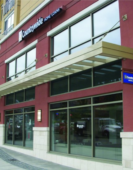
Aluminum storefronts, though similar in appearance to curtain wall systems, are based on simplified, lighter framing elements that are less expensive and quicker to assemble. Most storefront systems span vertically no more than 10 to 12 feet (3.0–3.7 m), although some, with heavier framing members or internal reinforcing, may span farther. Rather than being hung off the face of the building, as is common with curtain wall systems, storefront framing is installed between floor slabs or within wall openings (Figure 21.9). Most importantly, the use of lighter framing elements and simplified internal construction make storefront systems, in comparison to curtain wall systems, more limited in their ability to resist wind loads and water penetration. For these reasons, even improved storefront framing systems are not used more than three to four stories high on a building.
Figure 21.9 As the name implies, storefront systems are intended primarily for ground-level commercial glazing applications. These simple, field-assembled systems lack the greater capacity to resist wind loads and the more sophisticated water management features of curtain wall systems. (Photo by Joseph Iano.)
Aluminum window walls, like storefront, span between the top of one slab to the underside of the next. But more like curtain wall, they have internal water management features that make them suitable for use on tall buildings with exposure to higher wind pressures. In comparison to curtain wall, window walls more readily accommodate a variety of operable window types. They also allow more flexibility in installation, as they need not necessarily be erected in sequence from bottom to top of the building structure.
Aluminum curtain wall systems are the most high-performance, sophisticated, and costly of the aluminum-and-glass framing systems. Curtain wall systems can be readily applied to any number of stories. They use stronger, stiffer aluminum sections that can resist the higher wind pressures that act on taller buildings. Their methods of joining and attachment to the building structure can tolerate the larger movements that arise from structural deflections as well as from thermal expansion and contraction of the aluminum itself. They also include sophisticated internal construction and systems of sealing and water drainage that enable them to resist water leakage even under the more severe conditions of wind-driven rain to which they are exposed. It is to these types of systems that the majority of this chapter is devoted.
Modes of Assembly
Metal curtain wall systems can be classified according to their mode of assembly at the time of installation on the building (Figure 21.10). Many metal-and-glass curtain walls are furnished as stick systems whose principal components are metal mullions, and rectangular panels of glass and spandrel material that are assembled in place on the building (Figure 21.10a). Stick systems have the advantages of low shipping bulk and high degree of adjustability to unforeseen site conditions. But they must be assembled on site, under highly variable conditions, rather than in a factory with its ideal tooling, controlled environmental conditions, and lower wage rates. Aluminum entrances and storefronts are also typically installed as stick systems.
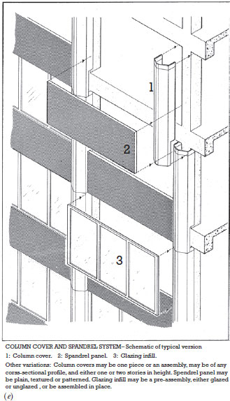
Figure 21.10 Modes of assembly for curtain walls. (a) Stick system. (b) Unit system. (c) Unit-and-mullion system. (d) Panel system. (e) Column-cover-and-spandrel system. (Reprinted with permission from AAMA Aluminum Curtain Wall Design Guide.)
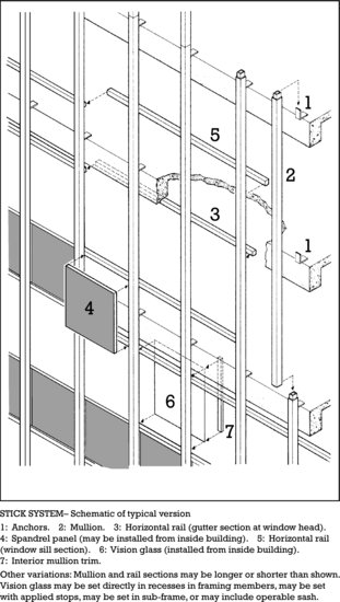
Figure 21.10 (Continued)
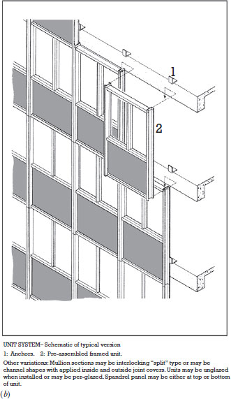
Figure 21.10 (Continued)
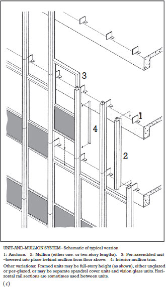
Figure 21.10 (Continued)
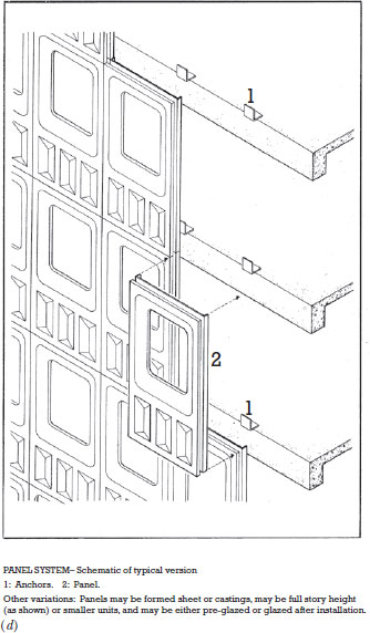
Figure 21.10 (Continued)
The unit (or unitized) system of curtain wall installation takes full advantage of factory assembly and minimizes on-site labor, but the units require more space during shipping and more protection from damage than stick system components (Figure 21.10b). The unit-and-mullion system (Figure 21.10c), which is seldom used today, offers a middle ground between the stick and unit systems.
The panel system (Figure 21.10d) is made up of homogeneous units that are formed from metal sheet. Its advantages and disadvantages are similar to those of the unit system, but its production involves the higher tooling costs of a custom-made die or mold, which makes it advantageous only for a building that requires a large number of identical panels.
The column-cover-and-spandrel system (Figure 21.10e) emphasizes the structural module of the building rather than creating its own grid on the facade, as the previously described systems do. A custom design must be created for each project because there is no standard column or floor spacing for buildings. Special care is required in detailing the spandrel panel support to ensure that the panels do not deflect when loads are applied to the spandrel beams of the building frame; otherwise, the window strips could be subjected to loadings that would deform the mullions and crack the glass.
Outside Glazing and Inside Glazing
An outside glazed curtain wall system requires that glass be installed or replaced by installers working from scaffolding or staging on the outside the building. An inside glazed cladding system allows glass installation to be performed from the inside. Inside glazing is more convenient and more economical for a tall building, but it requires a somewhat more elaborate set of extrusions. Outside glazing systems utilize simpler, less expensive shapes but are usually reserved for buildings only up to approximately three stories in height. Some curtain wall systems are designed so that they can be glazed from either side.
An Outside Glazed Curtain Wall System
An off-the-shelf, externally glazed stick system for aluminum-and-glass curtain walls is illustrated in Figures 21.11–21.16. This system is suitable for a low building whose walls workers can easily reach from external scaffolding.
Figure 21.11 The Kawneer 1600 System1® is an outside glazed stick system. Vertical mullions that run continuously from floor to floor support discontinuous horizontal mullions that are connected to them by means of shear blocks and screws. Each lite of glass sits on two rubber glazing blocks in the gutter of the horizontal mullion (not shown in this drawing). The inner surface of the glass rests against extruded rubber glazing gaskets pressed into small channels in both the vertical and horizontal mullions. Extruded aluminum pressure plates with rubber glazing gaskets are applied to both horizontal and vertical mullions to clamp the glass into place and create a weathertight seal. Each pressure plate is attached by means of screws that pass through drilled holes into an extruded screw slot. A thick rubber gasket in the screw slot acts as a thermal break. Snap-on covers conceal the screw heads and give a neat exterior appearance. A molded rubber plug at either end of each horizontal mullion contains any leakage or condensate within the horizontal mullion, from which it escapes via 5/16-inch-diameter (8-mm) weep holes (not shown here) drilled through the pressure plate and the bottom edge of the snap-on cover. Figures 21.12–21.16 further illustrate this system. (Courtesy of Kawneer Company, Inc.)

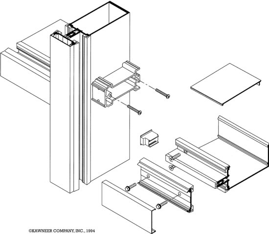
Figure 21.12 The manufacturer's details for the Kawneer 1600 System1 curtain wall are all keyed to the small elevation view at the upper left corner of this page. The details are reproduced here at one-quarter of their actual size. (Courtesy of Kawneer Company, Inc.) You can download a PDF of this figure at http://www.wiley.com/go/aflblce6ne.
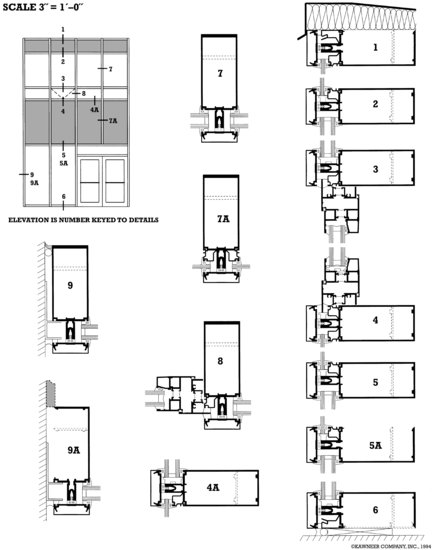
Figure 21.13 In this full-size detail of the vertical mullion for the Kawneer 1600 System1, we see that the basic extrusion is a rectangular box shape that is structurally stiff and presents a neat appearance inside the building. The broken lines indicate a smaller box mullion (162-002) that may be used for buildings with shorter floor-to-floor heights or smaller wind loads. The extruded plastic thermal break attaches to the mullion with a projecting “pine tree” spline that is pushed into the screw slot. Holes are drilled through the thermal break for the screws (not shown) that attach the pressure plate. The four rubber glazing gaskets attach to the aluminum pieces with projecting splines. (Courtesy of Kawneer Company, Inc.)
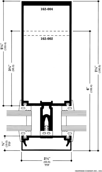
Figure 21.14 Two different horizontal mullion extrusions are available for the Kawneer 1600 System1. The closed extrusion (top) is used in most situations. The open-back extrusion (bottom) allows access to the shear block on the vertical mullion for purposes of assembly; it is used for portions of the wall that butt against other materials, such as heads, sills, and end bays. A snap-on cover closes the open back of the mullion, leaving only a virtually invisible seam. Rubber setting blocks are shown beneath the edges of the glass in both mullions. In the upper-left corner of the upper detail, a small aluminum extrusion has been added to allow the mullion to hold a single layer of spandrel glass or vision glass rather than the standard 1-inch (25-mm) double-glazing assembly. Weep holes are not shown; they are drilled horizontally through the pressure plate just above the thermal break and vertically through the bottom edge of the outside snap-on cover. (Courtesy of Kawneer Company, Inc.)
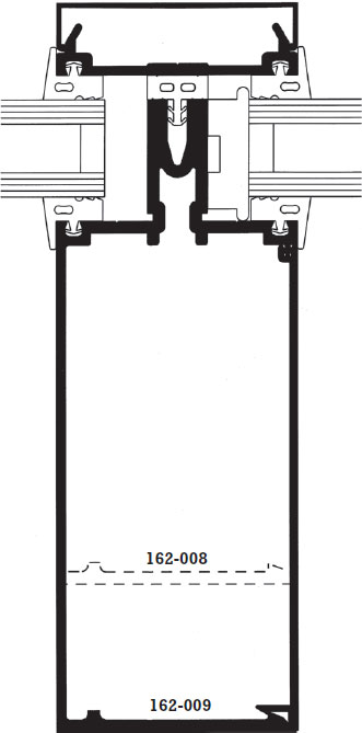
Figure 21.14 (Continued)
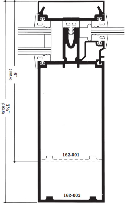
Figure 21.15 Vertical mullions of the Kawneer 1600 System1 are attached to the edges of the building's floors with the angle anchor shown in the top drawing. Sections of vertical mullion are spliced with the aluminum internal spline shown in the lower drawing. The spline is screwed to the lower section of mullion but the upper section is free to slide, which allows for thermal expansion and contraction. (Courtesy of Kawneer Company, Inc.)
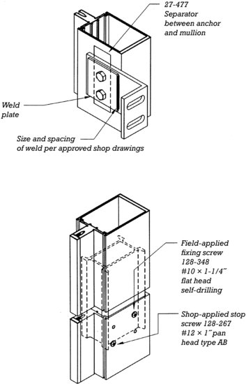
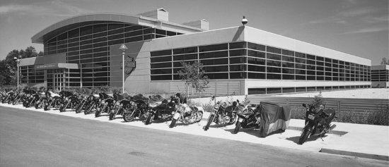
Figure 21.16 This building for the Harley-Davidson Motor Company in Wauwatosa, Wisconsin, features the Kawneer 1600 System1, whose details are shown in the previous series of figures. (Architect: Flad & Associates, Madison, Wisconsin. Courtesy of Kawneer Company, Inc.)
An Inside Glazed Curtain Wall System
An off-the-shelf, internally glazed stick system for aluminum-and-glass curtain walls is illustrated in Figures 21.17–21.23. This system is suitable for use on tall buildings, because it is installed entirely by workers who stand inside the building. Replacement of glass may also be done from within the building.
Figure 21.17 The Kawneer 1600 System4® may be glazed from either inside or outside the building. Inside glazing is usually preferred in taller buildings for its speed, safety, and convenience. (Courtesy of Kawneer Company, Inc.)
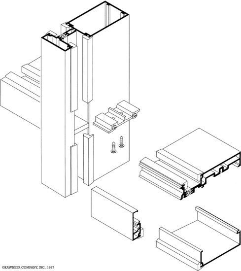
Figure 21.18 A complete set of details for the Kawneer 1600 System4, reproduced in the manufacturer's detail book at one-quarter of the full size. (Courtesy of Kawneer Company, Inc.) You can download a PDF of this figure at http://www.wiley.com/go/aflblce6ne.
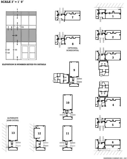
Figure 21.19 The vertical mullion for the Kawneer 1600 System4 is rigid, with no removable components except the glazing gaskets. The thermal break is an H-shaped extrusion of rigid plastic that is crimped securely into small grooves in the inner and outer portions of the mullion. Notice that the glazing pockets are of two different depths. This facilitates inside glazing, as explained in Figure 21.20. (Courtesy of Kawneer Company, Inc.)
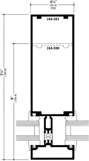
Figure 21.20 To glaze the Kawneer 1600 System4 from inside the building, rubber setting blocks are applied inside the shallow glazing pocket on the vertical mullion to cushion the edge of the glass. Rubber setting blocks are also installed in the horizontal mullion, and all the exterior-side glazing gaskets are inserted. Then the glass unit is pushed obliquely into the deep glazing pocket, squared away, and backed into the shallow pocket. (Courtesy of Kawneer Company, Inc.)
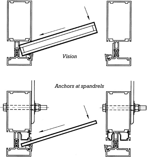
Figure 21.21 To make this mode of glass installation possible, the bottom half of the interior of each horizontal mullion is left off until the glass has been pushed into place. Then the bottom-half extrusion is added, and the interior glazing gaskets are installed. The interior gaskets are called “glazing wedges” because of their blunt wedge shape; this allows them to be installed simply by pressing them into place, wedging them between the glass and the mullion, after the glass has been installed. Notice how this shape is different from that of the exterior gaskets, which are installed before the glass. (Courtesy of Kawneer Company, Inc.)
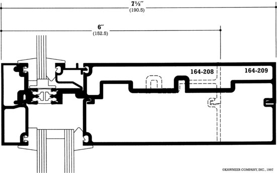
Figure 21.22 Before the glazing wedges are installed in the deep-pocket side of the vertical mullion, a W-shaped rubber block is flattened and slipped between the glass and the interior side of the mullion until it passes into the empty pocket. There it springs back into shape and prevents the glass from moving too deeply into the pocket. (Courtesy of Kawneer Company, Inc.)
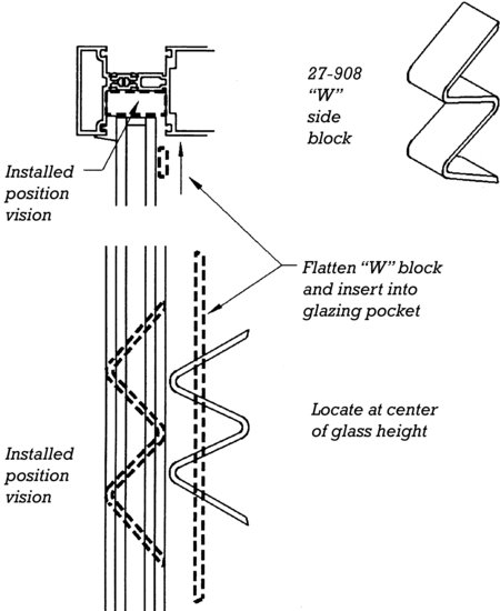
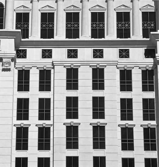
Figure 21.23 This Las Vegas casino hotel features the Kawneer 1600 System4, whose details are shown in Figures 21.17–21.22. (Courtesy of Kawneer Company, Inc.)
The Rainscreen Principle in Metal-and-Glass Curtain Walls
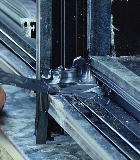
At first glance, neither of the curtain wall systems presented in this chapter might seem to be a rainscreen design, because both use rubber gaskets to seal around the glass on the outside of the wall as well as on the inside. However, consider what happens in either of these systems if both the inner and outer gaskets around a lite of glass are defective: During a wind-driven rain, gravity and capillary action would be likely to draw some water past the outer gasket into the spaces between the edges of the glass and the aluminum. However, as we discovered in Chapter 19, an imperfect inner gasket is unlikely to allow air currents strong enough to carry water farther toward the interior of the assembly. If water has leaked in along a vertical edge of the glass, it is contained within the vertical mullion and will fall by gravity to the bottom, where it drains out through weep holes. If water accumulates in the horizontal mullion, it is prevented from running out of the ends of the mullion by sealed rubber end plugs (Figure 21.24). Its only recourse is to drain to the outdoors through weep holes that are drilled horizontally through the pressure plate and vertically through the bottom edge of the external snap-on cover. Thus, the external gasket need serve only as a deterrent seal—essentially a rainscreen—to discourage water from entering without necessarily barring its entry altogether. The internal gasket serves as an air barrier, and the hollow spaces between the edges of the glass and the mullions act as pressure equalization chambers. The entire system functions as a rainscreen assembly. In practice, of course, the manufacturer and installer take every precaution to ensure that the external gaskets are properly installed and will act as positive barriers to the passage of water, but curtain wall systems do not depend on a perfect seal to retain their watertightness.
Figure 21.24 A curtain wall installer uses a putty knife to smooth silicone sealant into the joint between horizontal and vertical mullions. A rubber plug, as shown in Figure 21.11, previously inserted into the end of the horizontal mullion, is concealed by the sealant.
Expansion Joints in Metal-and-Glass Walls
Aluminum has a relatively high coefficient of thermal expansion. The coefficient for glass is less than half as much. Because the cladding of a building is exposed to air temperature fluctuations as well as direct heating by the sun, it must be provided with expansion joints to allow thermal movement to occur without damaging the cladding or the frame of the building.
The differences in thermal movement between the glass and the aluminum are generally accommodated by very small sliding and flexing motions that occur between the glass and the gaskets in which it is mounted. Rubber blocks placed between the edge of the glass and the mullion on either side of each lite prevent the glass from “walking” too far in either direction during repeated cycles of heating and cooling.
In the curtain wall systems illustrated in this chapter, vertical thermal movement in the aluminum is absorbed by telescoping joints that are provided at regular intervals in the vertical mullions (Figure 21.15). Horizontal thermal movement is accommodated by intentionally cutting horizontal aluminum components slightly short by a calculated fraction of an inch at each vertical connection. Because the horizontal mullions are interrupted at each vertical mullion, there are many of these joints to work together in absorbing horizontal expansion and contraction.
DOUBLE-SKIN FACADES
In a double-skin facade, the wall system is constructed of two separate glass cladding systems separated by an airspace that is wide enough in most cases to allow service personnel to pass between them. Double-skin facades have long been popular in European building construction and are now appearing in some North American buildings as well. Various configurations of glazing and treatment of the space between the two skins are possible. Most often, one of the two skins is double-glazed, while the other relies on single glass. The interstitial airspace may be ventilated to the interior of the building (when the outer skin is double-glazed) or to the exterior (when the inner skin is double-glazed). Natural ventilation of the building interior through operable openings in one or both skins is also possible. Ventilation of the interstitial space may be passive, that is, powered by natural convection; or active, accomplished with the aid of fans, and in some cases may be coupled to the building's HVAC system. Shading devices, such as louvered blinds or roller shades, manually controlled or driven by automatic timers or solar tracking devices, are also frequently integrated into the interstitial space.
Double-skin facades can reduce unwanted solar heat gain, increase daylighting potential, minimize thermal conduction and radiation through the wall system, provide a space for shading elements that is protected from the weather, permit natural ventilation designs in tall buildings, and create a quieter building interior than is possible with conventional glazing systems. Against these potential benefits must be weighed the disadvantages: The airspace may subtract as much as 5 to 10 percent of the usable floor area of the building. Though the second skin of the facade may be constructed of less expensive framing and glass than the first skin, this still constitutes a significant increase in construction cost over a traditional curtain wall. Also, during the life of the building, twice as much glass surface must be washed on a regular basis.
Given these trade-offs, double-skin facade systems are most appropriate for glass walls that must meet stringent energy conservation targets, where the building owner's financial planning allows the higher cost of construction to be amortized over a relatively long time period in which it can be offset by increased energy savings, and where the creation of a high-performance building is an implicit goal of the building program.
SLOPED GLAZING
Many buildings feature glass roofs over such areas as lobbies, restaurants, cafes, swimming pools, garden courtyards, and other amenities. A glass roof presents particular problems with respect to potential water leakage, because it is impossible to neutralize the force of gravity on a surface that is not vertical. Furthermore, moisture that condenses on the interior surfaces of the glass can accumulate and drip onto occupants below. Therefore, sloped glazing systems are designed to include an internal drainage system. This drainage system collects water that results from leakage or condensation and channels it to the outdoors. The glass surface is sloped rather than absolutely flat because the slope enables gravity to assist in keeping water from ponding on the roof, in causing condensate to run to the lower edge of each lite of glass before dripping off, and in moving water through the drainage channels to the weep holes through which it is conducted back to the outdoors.
The sloped glazing illustrated in Figures 21.25 and 21.26 is designed to adapt to a range of slopes from 15 to 60 degrees. Water leakage is discouraged by a well-designed system of glazing gaskets. But if leakage should occur because of gasket deterioration or faulty installation, the internal drainage system will catch it along any purlin or rafter and drain it away. Moisture condensation is minimized by double glazing and thermal breaks. Any condensate that may form under extreme conditions is also caught and drained by the same system of channels in the aluminum members.
Figure 21.25 The Kawneer 1600 S.G.® sloped glazing system is framed with aluminum extrusions that incorporate internal gutters to drain away condensate and incidental leakage. (Courtesy of Kawneer Company, Inc.)
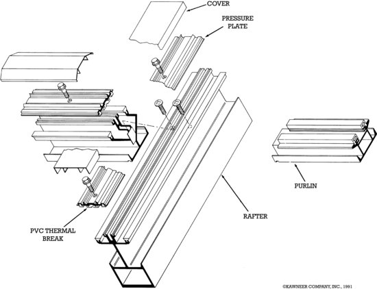
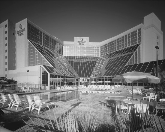
Figure 21.26 This hotel in Orlando, Florida, includes massive areas of Kawneer 1600 S.G. sloped glazing. Reflective glass is used to minimize solar overheating of the interior space. (Courtesy of Kawneer Company, Inc.)

For glass systems sloped more than 15 degrees from vertical, building codes restrict the types of glass used, to protect occupants below from the risk of injury from falling broken glass. The only glazing materials permitted without any limitations are laminated glass and plastic. Other glass types are permitted, subject to restrictions relating to the height of the glass above the floor, size of the lites, type of occupancy, and other factors. Alternatively, any glass type is permitted if a metal screen is installed below the glass that can catch shards should the glass break.
THE CURTAIN WALL DESIGN AND CONSTRUCTION PROCESS
Metal curtain wall design is not undertaken by an architect alone; it is too complex and specialized a process. For many buildings, the architect simply adopts a proprietary system that meets design requirements. This puts the primary responsibility on the manufacturer and installer of the system to ensure that the proper components are chosen and the wall is correctly installed.
When an architect sets out to design a new system of metal cladding, as is often done for large, important buildings, other professionals are brought into the process. A cladding consultant brings unique experience and specialized expertise to the effort. The structural engineer must understand the weight and attachment requirements of the system and how wind loads acting on the curtain wall will be transferred to the building frame. This engineer must also define the deflection criteria of the building structure and communicate this information to those responsible for the design of the curtain wall. A curtain wall manufacturer is also brought into the design team early in the process.
The architect and building owner may elect either of two methods for selecting a manufacturer: One curtain wall manufacturer may be chosen on the basis of reputation and past experience. Alternatively, the architect and cladding consultant may prepare a rough design and performance specifications and submit these to several manufacturers for proposals. Each manufacturer will then submit a more detailed design and a financial proposal, and one will be selected on the basis of these proposals to proceed with the project.
The manufacturer understands better than any other member of the team the manufacturing, assembly, installation, and cost implications of a new curtain wall design. The manufacturer often does the installation as well as the manufacturing of the components, or it subcontracts the installation work to companies that it certifies to be well qualified and familiar with the manufacturer's products and standards. This installation experience is also invaluable during the design process.
From conceptual drawings prepared by the architect and the cladding consultant, the manufacturer prepares a more detailed set of design drawings as a basis for reaching preliminary agreement on the design. The manufacturer then prepares a very detailed set of shop drawings and installation drawings. These are checked carefully by the architect, engineer, and cladding consultant to ensure compliance with the design intentions and the structural capabilities of the building frame. Full-scale testing of the curtain wall, as described in Chapter 19, is usually carried out before the manufacture of a custom-designed curtain wall system is authorized to begin. The curtain wall manufacturer may also visit the construction site during the erection of the building frame to become familiar with the level of dimensional accuracy of the structural surfaces to which the curtain wall will be fastened.
METAL PANEL CLADDING
Although the primary focus of this chapter is aluminum-framed glass curtain walls, metal is also used to form cladding panels of a variety of types. These panels can be glazed into curtain wall and other aluminum framing systems, much as glass is, or they can be used as independent cladding systems in their own right.
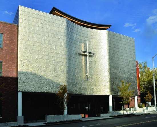
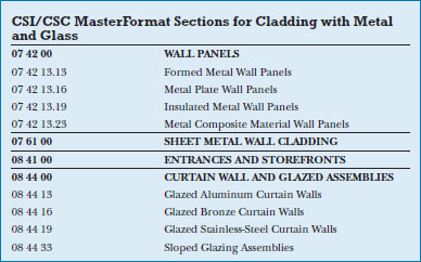
Architectural sheet metal cladding, made of thin, flexible metal sheets, is applied to walls in very much the same way as this type of metal is used for roofing, illustrated in Chapter 16. Because the metal is thin and requires closely spaced seams and clips to hold the panels in place, the choices of seam type and arrangement tend to figure prominently in the finished expression of the cladding (Figure 21.27). Sheet metal can also be factory-formed into various ribbed or corrugated shapes called formed metal wall panels. These are usually attached with regularly spaced exposed fasteners and resilient washers that deter water leakage at the penetrations through the panels. The profile of corrugation or ribs is the dominant architectural feature of this panel type (Figure 16.53).
Figure 21.27 Titanium sheet metal cladding, purposefully “crinkled” to create a surface with many specular highlights. See Chapter 16 for a more in-depth discussion of architectural sheet metal materials and methods of installation. (First Methodist Church, Seattle, WA; Bassetti Architects. Photo by Joseph Iano.)
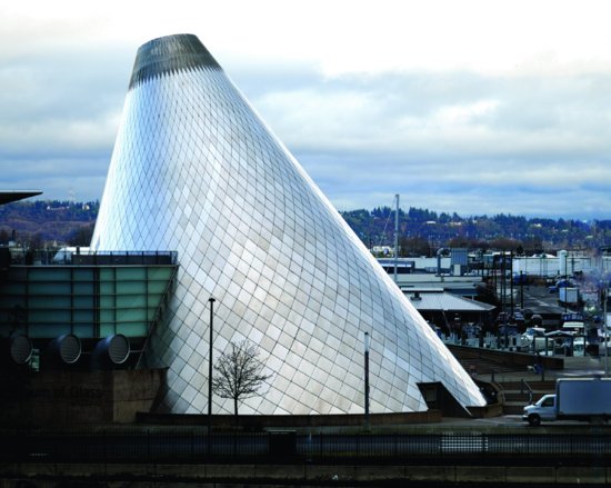
Metal plate wall panels are made from heavier metal sheet, usually about 1/8-inch (3 mm) thick. When properly detailed for thermal expansion and contraction, these stiffer panels are capable of producing consistently flat or smoothly curved exterior surfaces with precise, uniform edges. Seams can be spaced at greater distances than sheet metal cladding. Rather than overlapping the edges of adjacent sheets as is common in sheet metal cladding, panel edges can be kept flush, with a uniform gap in between (Figure 21.28). Composite metal wall panels, similar in thickness to solid metal panels, are made from sheet metal laminated to both sides of a thermoset plastic core. Though lower in cost than solid metal panels, the detailing and architectural expression are quite similar. Composite metal panels made with other core materials, such as metal foil honeycomb, are made in a range of thicknesses up to 1 to 2 inches (25–50 mm). Both of these panel types can be attached to metal furring or framing components behind the panels that, in turn, are fastened to a backup wall that also supports insulation and other components of the exterior enclosure. Both exposed and hidden fastener systems are possible, and installations can be designed to function as either a barrier wall or rainscreen (see, for example, Figures 19.8 and 19.9).
Figure 21.28 Diamond-shaped stainless steel metal plate panels are used to clad a conical dome. (Museum of Glass, Tacoma, WA; Arthur Erickson, architect. Photo by Joseph Iano.)
Insulated metal panels consist of sheet metal laminated to both sides of a rigid foam plastic insulating core. When fabricated with a complete system of interlocking edge seams, these lightweight, easily erected panels can provide many of the separate enclosure functions of the exterior wall in one factory-made component, including control of the passage of heat, exterior moisture, air, and interior water vapor. Panels can be designed as a barrier wall system, or, with the addition of an airspace and airtight drainage plane behind the panels, as a rainscreen system (Figures 21.29, 21.30).
Figure 21.29 CENTRIA Formawall® aluminum-skinned, insulating metal panels are supported by vertical framing members aligned behind the panel joints. Each panel is mechanically fastened to the frame at the top corners, seen here in the middle of the picture. The bottom edge of the panel is held in place by its interlocking joint with the panel below. Solid gaskets between panels and sealant between panels and backing complete the air and watertightness of the assembly. (Images courtesy of CENTRIA. Formawall¯ is registered trademark of Centria.)

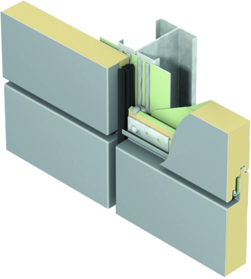
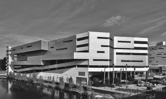
Figure 21.30 An enclosure combining perforated and solid metal panels gives this parking a garage a sleek, modern appearance. (Image courtesy of CENTRIA.)
KEY TERMS
REVIEW QUESTIONS
1. For what reasons is aluminum the metal most frequently used in metal-and-glass cladding systems?
2. What are the relative advantages and disadvantages of a stick system and a panel system?
3. What are some characteristic features of aluminum extrusions, and what is the function of each?
4. What are the most common finishes applied to aluminum curtain wall components? What are the advantages of each?
5. How would you choose between an inside glazed system and an outside glazed one?
6. Explain the differences between aluminum-framed entrances, storefronts, and curtain walls. What is an appropriate application for each?
7. In what way is a slope glazing system more difficult to make watertight than a wall cladding system? How is this reflected in the details of a slope glazing system?
EXERCISES
1. Make photocopies of full-scale details of the vertical and horizontal mullions of a metal curtain wall system from a manufacturer's catalog. Paste the details on a larger sheet of paper and add notes and arrows to explain every aspect of them: the features of the extrusions, the gaskets and sealants, the glazing materials and methods, drainage, insulation, thermal breaks, rainscreen features, and so on. From your examination of the details, list the order in which the components would be assembled. Is the system glazed from inside the building or outside? How can you tell?
2. Design a coffee table that is made up of aluminum extrusions and a glass top. Design and draw complete details of the extrusions and connections. Select a surface finish for the aluminum. What type of glass will you use?
SELECTED REFERENCES
American Architectural Manufacturers Association. Aluminum Curtain Wall Design Guide Manual. Schaumburg, IL, Author, 2005.
This publication covers its topic in exemplary fashion with clear text and beautifully prepared illustrations. The same organization also publishes a series of more specialized publications on various aspects of metal-and-glass curtain walls: rainscreen design, care and handling of aluminum components, design of wind loads and wind tunnel testing, fire safety, test methods, installation procedures, finishes, and so on.
WEB SITES
Cladding with Metal and Glass
Author's supplementary web site: www.ianosbackfill.com/21_cladding_with_metal_and_glass
Aluminum Extruders Council: www.aec.org
American Architectural Manufacturers Association: www.aamanet.org
Centria curtain wall: www.centriaperformance.com
EFCO curtain wall: www.efcocorp.com
Formacore Curtain Walls: www.portafab.com/curtain_walls.shtml
Kawneer curtain wall and windows: www.kawneer.com
Whole Building Design Guide, Curtain Walls: www.wbdg.org/design/env_fenestration_cw.php
