
A worker lays acoustical panels in a recessed grid to create a suspended ceiling. (Photo courtesy of United States Gypsum Company.)
24
FINISH CEILINGS AND FLOORS
Exposed Structural and Mechanical Components
Types of Finish Flooring Materials
FINISH CEILINGS
Functions of Finish Ceilings
The ceiling surface is an important functional component of a room. It helps control the diffusion of light and sound about the room. It may play a role in preventing the passage of sound vertically between the rooms above and below, and horizontally between rooms on either side of a partition. It is often designed to resist the passage of fire and must itself be appropriately noncombustible. Frequently, it is called upon to assist in the distribution of conditioned air, artificial light, and electrical energy. In many buildings, it must accommodate sprinkler heads for fire suppression and loudspeakers for intercommunication systems. And its color, texture, pattern, and shape are prominent in the overall visual impression of the room. A ceiling can be a simple, level plane, a series of sloping planes that give a sense of the roof above, a luminous surface, a richly coffered ornamental ceiling, or even a frescoed plaster vault such as Michelangelo 's famous ceiling in the Sistine Chapel in Rome; the possibilities are endless.
TYPES OF CEILINGS
Exposed Structural and Mechanical Components
In many buildings, it makes sense to omit finished ceiling surfaces altogether and simply expose the structural and mechanical components of the floor or roof above (Figures 24.1, 4.20). In industrial and agricultural buildings, where appearance is not of prime importance, this approach offers the advantages of economy and ease of access for maintenance. Many types of floor and roof structures are inherently attractive if left exposed, such as heavy timber beams and decking, concrete waffle slabs, and steel trusses. Other types of structures, such as concrete flat plates and precast concrete planks, have little visual interest, but their undersurfaces can be painted and left exposed as finished ceilings in apartment buildings and hotels, which have little need for mechanical services at the ceiling. This saves money and reduces the overall height of the building. In some buildings, the structural and mechanical elements at the ceiling, if carefully designed, installed, and painted, can create a powerful aesthetic of their own.
Figure 24.1 Air conditioning ductwork, electrical conduits, fluorescent lighting fixtures, skylights, curtain gymnasium area dividers, and athletic equipment are exposed in a ceiling structure of painted open-web steel joists and corrugated steel decking. (Weinstein A|U, Architects. Photo by Joseph Iano.)
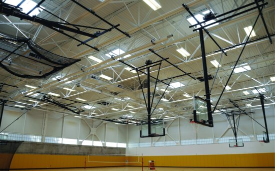
Exposing structural and mechanical components rather than covering them with a finished ceiling does not always save money. Mechanical and structural work is not normally done in a precise, attractive fashion because it is not usually expected to be visible, and it is less expensive for workers to take only as much care in installation as is required for satisfactory functional performance. To achieve perfectly straight, neatly sealed ductwork that is free of dents, steel decks without rust and weld spatter, and square, well-organized runs of electrical conduit and plumbing, the drawings and specifications for the project must tell exactly the results that are expected, and a higher labor cost must be anticipated.
Tightly Attached Ceilings
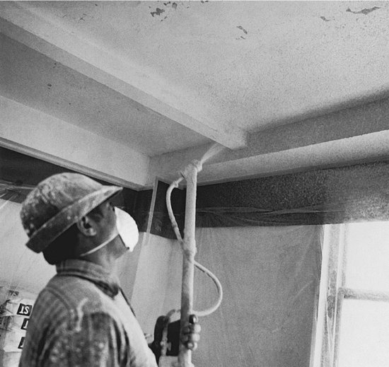
Ceilings of almost any material can be attached directly to the underside of the structure above. Commonplace examples include gypsum board or plaster mounted directly to the underside of wood or steel joists and rafters, acoustical tile adhered to the underside of a concrete deck, or textured, acoustic materials spray-applied to the underside of concrete slabs or corrugated metal decking (Figure 24.2). When finish ceilings are in direct contact with the structure above, special finishing arrangements must be worked out for any beams and girders that protrude through the plane of the ceiling, and for ducts, conduits, pipes, and sprinkler heads if these elements are located below the ceiling.
Figure 24.2 Spraying a textured finish onto the underside of a concrete slab in a residential building, where there are no pipes, ducts, or wires to be concealed below the plane of the floor structure. (Courtesy of United States Gypsum Company.)
Suspended Ceilings
A ceiling that is suspended on wires some distance below the floor or roof structure can hang level and flat despite varying sizes of girders, beams, joists, and slabs above, and even under a roof structure that slopes toward roof drains. Ducts, pipes, and conduits can run freely in the plenum space between the ceiling and the structure above. Lighting fixtures, sprinkler heads, loudspeakers, and fire detection devices may be recessed into the ceiling. Such a ceiling can also—at additional cost—serve as a membrane ceiling or membrane fire protection for the floor or roof structure above, eliminating the need for fussy individual fireproofing of steel joists, or imparting a higher fire resistance rating to wood or precast concrete structures. For these reasons, suspended ceilings are a popular and economical feature in many types of buildings, especially office and retail structures.
Suspended ceilings can be made of almost any material; the ones most widely used are gypsum board, plaster, and various proprietary panels and tiles composed of incombustible fibers or other material. Each of these is supported on its own system of small steel framing members that hang from the structure on heavy steel wires.
Suspended Gypsum Board and Plaster Ceilings
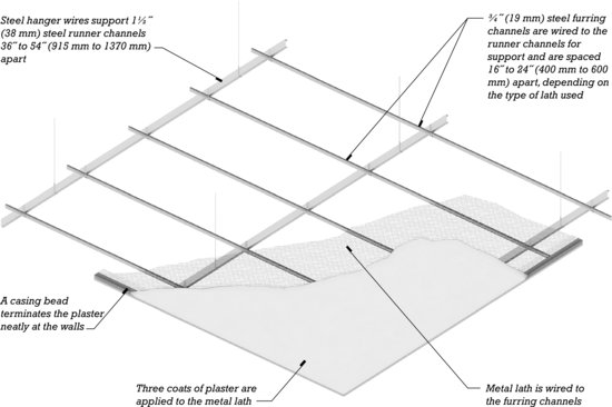
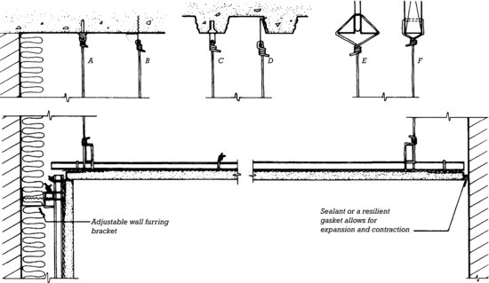
Suspended plaster ceilings, assembled from steel hanger wire and cold-rolled channels, have been in use for many decades; typical details are shown in Figure 24.3. Although most suspended plaster ceilings are flat, lathers are capable of constructing ceilings that are richly sculpted, ranging from configurations resembling highly ornamented Greek or Roman coffered ceilings to nearly any form that the contemporary designer can draw. This capability is especially useful in auditoriums, theaters, lobbies of public buildings, and other uniquely shaped rooms.
Figure 24.3 A suspended metal lath-and-plaster ceiling. At the top of the page is a cutaway isometric drawing, as viewed from below, of the essential ceiling components. Across the center of the page are details of six ways of supporting the hanger wires: (A) A pin is powder-driven into a concrete structure. (B) A corrugated sheet metal tab with a hole punched in it is nailed to the formwork before the concrete is poured. When the formwork is stripped, the tab bends down and the hanger wire is threaded through the hole. (C) A sharp, daggerlike tab of sheet metal is driven through the corrugated metal decking before the concrete topping is poured. (D ) A sheet metal hook is hung onto the lap joints in the metal decking. (E) The hanger wire is wrapped around the lower chord of an open-web steel joist. (F ) The hanger wire is passed through a hole drilled near the bottom of a wood joist. At the bottom of the page is a section through a furred, insulated plaster wall and a suspended plaster ceiling. You can download a PDF of this figure at http://www.wiley.com/go/aflblce6ne.
(a)
(b)
Gypsum board suspended ceilings may be screwed to the same type of suspension system as shown in Figure 24.3 for plaster, or to light gauge steel framing made up of stud or joist members. Special components have been developed that make it easy to suspend more complex shapes, such as cylindrical vaults, undulating surfaces, and deep coffers.
Perforated gypsum panels, manufactured with attractively arranged patterns of small holes, are used in gypsum board ceilings where enhanced acoustic performance is required. Panels are mounted to special suspension systems that eliminate the need for normal taping and finishing. With the addition of a layer of acoustic insulation over the top of the panels, acoustic ratings comparable to those of suspended acoustical ceilings, discussed below, are possible.
Suspended Acoustical Ceilings
Ceilings made from fibrous materials in the form of lightweight tiles or panels are customarily referred to as acoustical ceilings because most of them are absorptive of sound energy, unlike plaster and gypsum board, which are highly reflective of sound. They are also often less costly than either plaster or gypsum board ceilings. The sound absorption performance of a ceiling material is measured as its Noise Reduction Coefficient (NRC). NRC is a number between 0 and 1, with higher values indicating better sound absorption at four specific frequencies ranging from 250 Hz to 2000 Hz. An NRC of 0.85 indicates that the material absorbs 85 percent of the sound that reaches it and reflects only 15 percent back into the room. NRCs for most acoustical ceiling materials range from 0.50 to 0.90, compared to values below 0.10 for plaster and gypsum board ceilings. This makes acoustical ceilings valuable for reducing noise levels in lobbies, office spaces, restaurants, retail stores, recreational spaces, and noisy industrial environments.
The lightweight, porous materials that produce high NRC ratings allow most sound energy to pass through. In other words, a ceiling made of porous materials will not furnish very good acoustic privacy between adjacent rooms unless a suitable full-height wall separates the rooms and blocks the ceiling plenum. The ability of a ceiling system to reduce sound transmission from one room to another through a shared plenum is measured by its Ceiling Attenuation Class (CAC). CAC is measured in decibels, with higher values representing greater reductions in sound transmission. For closed offices with shared ceiling plenums, a ceiling system with a CAC of not less than 35 to 40 is recommended. Dense, nonporous ceiling materials tend to have higher CACs than lighter, more porous materials.
A third measure of ceiling acoustical performance is Articulation Class (AC ). Like NRC, AC is a measure of sound reflection and absorption. However, AC is intended specifically to measure a ceiling system's contribution to speech clarity and privacy in a typical open office environment. It measures a ceiling's absorption and reflection of sound over a 60-inch (1500-mm)-high partition at frequencies ranging from 500 to 4000 Hz, those particularly critical to normal speech. Higher AC values represent greater acoustical clarity and privacy, with minimum recommended values falling in the range of 170 to 200.
Where both noise reduction within a space and sound attenuation between spaces are required simultaneously, composite ceiling panels with an absorbent material laminated to a dense substrate may be used; these have high values for both noise reduction (NRC or AC) and sound attenuation (CAC). The same result can be achieved by mounting acoustically absorbent tiles on a suspended ceiling of plaster or gypsum board.
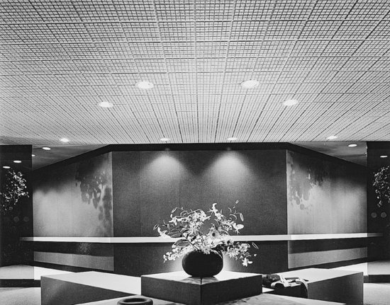
The most economical acoustical ceiling systems consist of lay-in panels that are supported by an exposed grid (Figures 24.4 and 24.5). Any panel in the ceiling can be lifted and removed for access to services in the plenum space. For a neater appearance, a concealed grid system may be used. Concealed grid systems require special panels for plenum access. For curved ceilings, curvilinear grid systems and flexible tiles are used to create ceilings that warp along one or both axes of the ceiling plane. Suspended acoustical ceilings are available in hundreds of different designs. Figures 24.6–24.10 show some typical examples.
Figure 24.4 Acoustical ceilings are supported on suspended grids of tees formed from sheet metal. At the top of the figure is a cutaway view looking up at an acoustical ceiling of lay-in panels. Below are sections illustrating how the grid may be exposed, recessed, or concealed for different appearances.
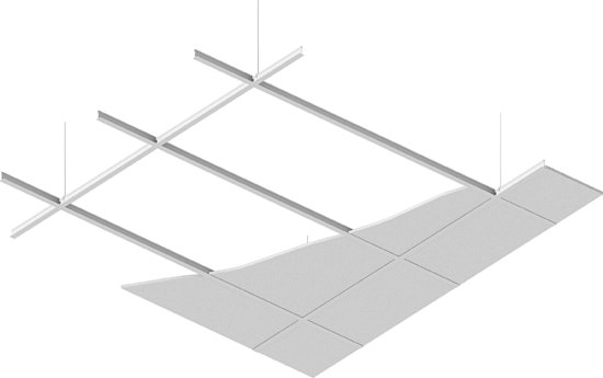
Figure 24.4 (Continued)
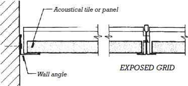
Figure 24.4 (Continued)
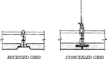
Figure 24.5 The grid for an acoustical ceiling is assembled with a simple interlocking joint.
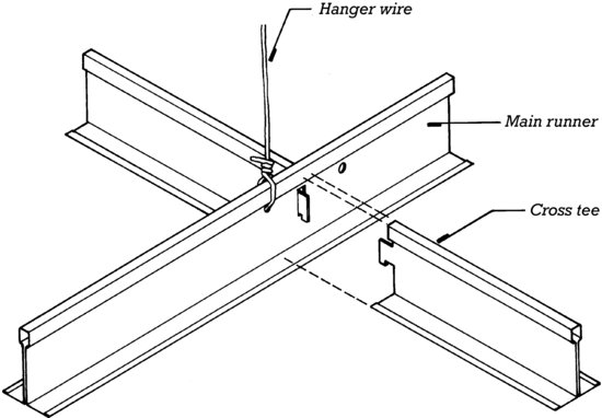
Figure 24.6 Many acoustical ceilings are manufactured as integrated ceiling systems that incorporate the lighting fixtures and air conditioning outlets into the module of the grid. In this integrated ceiling, viewed from above, the hanger wires, grid, acoustical panels, fluorescent lighting fixture, and distribution boot for conditioned air have been installed. The boot will be connected to the main ductwork with a flexible oval duct. (Photo courtesy Armstrong World Industries.)
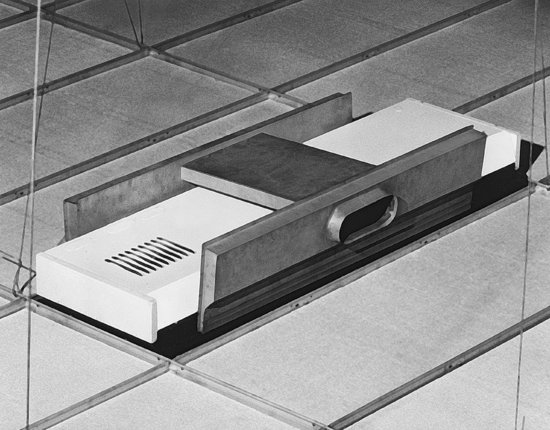
Figure 24.7 Air distribution in this integrated acoustical ceiling is through slots that occur between panels. Lighting fixtures, loudspeakers, and smoke detectors are incorporated simply and unobtrusively. (Courtesy of United States Gypsum Company.)
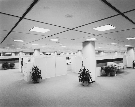
Figure 24.8 Locations of HVAC diffusers and suspended lighting fixtures are carefully coordinated with the grid layout of this suspended acoustical tile ceiling. Fire sprinklers, a smoke detector, and a fire annunciator are mounted flush to the underside of the ceiling. (Photo by Joseph Iano.)
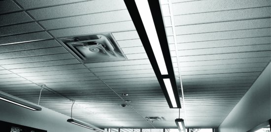
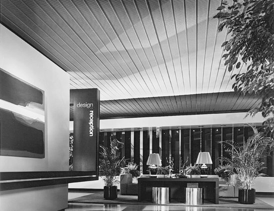
Figures 24.9 and 24.10 A variety of patterns and textures are available in acoustical ceilings. (Photos courtesy Armstrong World Industries.)
Economy has worked so great a change in our dwellings, that their ceilings are, of late years, little more than miserable naked surfaces of plaster. [A discussion of ceiling design will] possess little interest in the eye of speculating builders of the wretched houses erected about the suburbs of the metropolis, and let to unsuspecting tenants at rents usually about three times their actual value. To the student it is more important, inasmuch as a well-designed ceiling is one of the most pleasing features of a room.
—Joseph Gwilt, The Encyclopedia of Architecture, London, 1842
Other Suspended Ceiling Materials
Almost any material can be incorporated into a suspended ceiling system. Metal panel ceilings are made from sheet metal suspended in a manner similar to that for acoustic panels (Figure 24.11). Linear metal ceilings are made from longer metal strips suspended on a concealed grid system (Figure 24.12). The metal sheets may be solid or perforated, and formed flat, stamped with intricate patterns, or curved, depending on aesthetic and acoustic requirements. Due to its ease of formability and light weight, aluminum is the metal most commonly used.
Figure 24.11 Trapezoidal panels in a curved, stepped, metal panel ceiling. Air distribution, recessed lighting, and sprinklers are neatly integrated into the ceiling system. (Photo by Joseph Iano.)
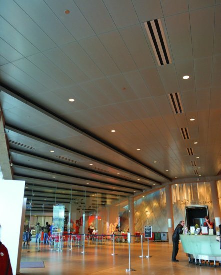
Figure 24.12 A mirror-finish linear metal suspended ceiling, with an exposed steel space truss structure beyond. (Architect: DeWinter and Associates. Photo courtesy of Alcan Building Products, division of Alcan Aluminum Corporation.)

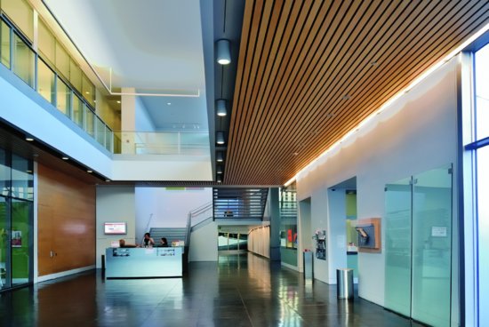
Suspended wood ceilings, made from solid wood or wood veneered over a variety of substrates, are produced in both panel and linear forms, similar to those of metal (Figure 24.13). Textile ceilings may be made from fabric-wrapped ceiling panels, consisting of natural or synthetic fabrics mounted over acoustic panels. Larger, seamless textile ceilings are constructed as stretched-fabric ceiling systems in which a synthetic fabric is stretched across a special mounting system with acoustic insulation behind the fabric. Wherever flammable materials are used in ceilings, these materials must meet the fire criteria requirements discussed in Chapter 22.
Figure 24.13 A linear wood ceiling defines the main circulation spine through a museum entrance lobby. (Photo by Joseph Iano.)
With the advent of three- dimensional modeling and computer-driven fabrication techniques, the ability to produce economical yet unique ceiling panel forms continues to grow, further expanding the range of possibilities in suspended ceiling types and designs.
Suspended Fire-Resistance Rat ed Ceilings
Membrane ceilings, designed to contribute to the fire resistance of the roof or floor structure above, may be made of gypsum board, plaster, or lay-in panel and grid systems. These ceilings must be carefully detailed and installed to maintain the required fire resistance throughout the extents of the ceiling: Lighting fixtures must be backed up with fire-resistive material, air conditioning grills must be isolated from the ducts that feed them by automatic fire dampers, access panels provided for maintenance of above-ceiling services must themselves meet the same fire resistance rating as the ceiling system, and any other penetrations must be appropriately treated.
Interstitial Ceilings
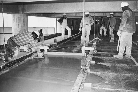
Many hospital and laboratory buildings have extremely elaborate mechanical and electrical systems, including not just the usual air conditioning ducts, water and waste piping, and electrical and communications wiring, but also such services as fume hood ducting, fuel gas lines, compressed air lines, oxygen piping, chilled water piping, vacuum piping, and chemical waste piping. These ducts and tubes occupy a considerable volume of space in the building, often in an amount that virtually equals the inhabited volume. Furthermore, all these systems require continual maintenance and are subject to frequent change. As a consequence, many laboratory and hospital buildings are designed with interstitial ceilings. An interstitial ceiling is suspended at a level that allows workers to travel freely in the plenum space, usually while walking erect, and is structured strongly enough to safely support the weight of the workers and their tools. In effect, the plenum space becomes another floor of the building, slipped in between the other floors, and the overall height of the building must be increased accordingly. Its advantage is that maintenance and updating work on the mechanical and electrical systems of the building can be carried on without interrupting the activities below. Interstitial ceilings are made of gypsum or lightweight concrete and combine the construction details of poured gypsum roof decks and suspended plaster ceilings. Figure 24.14 shows the installation of an interstitial ceiling.
- Acoustical ceiling tile can be a source of volatile organic compound (VOC) emissions as well as a reservoir for emissions from other sources.
- Low-emitting acoustic tiles are available, as are tiles with high recycled materials content.
- When the space above suspended ceilings is used as a return air plenum for the building's HVAC system, contaminants and emissions from the acoustical tile can be introduced into the system's airstream and redistributed to other parts of the building.
- Concrete, stone, masonry, ceramic tile, and cementitious mortars and grouts are chemically inert and generally free of emissions.
- Organic adhesives used in tiling and resins used in thin-set terrazzo may be sources of emissions.
- Sealers applied to hard flooring materials to provide water repellency and protection from staining are potential sources of emissions. Solvent-based sealers generally have higher emissions than water-based products.
- Considerations of sustainability in wood products are discussed in Chapter 3 of this text.
- Bamboo is harvested in a 4- to 6-year cycle and is considered a rapidly renewable material. Some bamboo flooring products are produced with urea-formaldehyde glues, a potential source of emissions. Others are manufactured with alternative low-emitting adhesives.
- Finishes for wood and bamboo flooring are potential sources of emissions. Water-based finishes and waxes are generally lower emitting than solvent-based finishes, but they may not be as durable or as easy to apply.
- Self-leveling cements used to prepare subfloors for resilient flooring coverings are potential sources of emissions.
- Vinyl (polyvinyl chloride) is a component of many resilient floor coverings and other interior finish products. It has an embodied energy of approximately 30,000 BTU per pound (70 MJ/kg). Issues related to the environmental sustainability of this material are discussed at greater length in Chapter 18.
- The embodied energy of synthetic rubber is about 50,000 BTU per pound (120 MJ/kg), and that of natural late x rubber is about 30,000 BTU per pound (70 MJ/k g).
- Some rubber flooring is manufactured from recycled car tires. Natural rubber is a renewable resource extracted from tropical rubber plants without harming the plant.
- Linoleum is made from linseed oil, pine rosin, clay, cork, limestone, and jute. Many of its ingredients are renewable, although the extraction of clay and limestone can cause ecological disruption.
- Cork is a renewable material harvested in a 9-year cycle.
- VOC emissions from the stripping and rewaxing of resilient flooring over its lifetime can be many times greater than those originating from the flooring material itself.
- Resilient flooring meeting the Resilient Floor Institute's Floor Score requirements for low VOC emissions satisfy current LEED requirements for low-emitting floor materials.
- The embodied energy of nylon carpet is roughly 65,000 BTU per pound (150 MJ/kg), that of polypropylene is 40,000 BTU per pound (93 MJ/kg), and that of wool is 45,000 BTU per pound (105 MJ/kg). In general, natural fibers tend to be lower in embodied energy than synthetic fibers but also less durable.
- Many carpets and cushions are made with at least some recycled material.
- Carpet, cushions, and adhesives meeting the requirements of the Carpet and Rug Institute's Green Label Plus program satisfy current LEED requirements for low- emitting carpet systems.
- Factory-applied adhesives tend to have lower VOC emissions than adhesives applied on the construction site.
- Stretch-in installation of sheet carpet and free-lay installation of carpet tile (methods of installation explained later in this chapter) eliminate the need for carpet adhesive.
- Carpets can become reservoirs for VOCs emitted by other materials, as well as for bacteria, microbes, dust mites, and other contaminants.
- Carpet tile, which allows easy spot replacement, lessens the need for full carpet replacement when a small area becomes worn or damaged, thus extending the life of the carpet installation and reducing waste.
- Recycling of used carpet is complicated by the fact that many different fibers, which must be recycled separately, are used. Some manufacturers are introducing “close-the-loop” reclamation programs in which they will recycle or repurpose their own products to prevent them from being disposed of in landfills.
Figure 24.14 The final steps in constructing an interstitial ceiling: The ceiling plane consists of gypsum reinforced with hexagonal steel mesh. It is framed with steel truss tee subpurlins, the tops of which are visible at the right of the picture, supported by steel wide-flange beams suspended on rods from the sitecast concrete framing above. The final layer of gypsum is being pumped onto the ceiling from the hose near the center of the picture. The wet gypsum is struck off level with the wooden straightedge seen here hanging on the beams, and is then troweled to a smooth walking surface. When the gypsum has hardened, installation of the ductwork, piping, and wiring in the interstitial plenum space can begin, with workers using the gypsum ceiling as a walking surface. (Photo compliments Keystone Steel & Wire Co.)
FINISH FLOORING
Functions of Finish Flooring
Floors have a lot to do with our visual and tactile appreciation of a building. We sense their colors, patterns, and textures, their “feel” underfoot, and the noises they make in response to footsteps. Floors affect the acoustics of a room, contributing to a noisy or hushed quality, depending on whether a hard or soft flooring material is used. Floors also interact in various ways with light: Some floor materials give mirror-like reflections; others give diffuse reflections or none at all. Dark flooring materials absorb more of the light incident upon them and contribute to the creation of a darker room, whereas light materials help create a brighter space and in some cases, can even contribute to reduced energy consumption by allowing artificial lighting levels to be lowered.
Floors are also a major functional component of a building. They are its primary wearing surfaces, subject to water, grit, dust, and the abrasive and penetrating actions of feet and furniture. They require more cleaning and maintenance effort than any other component of a building. They must be designed to deal with problems of skid resistance, sanitation, noise reduction between floors of a building, and even electrical conductivity in occupancies such as computer rooms and hospital operating rooms, where static electricity would pose a threat. Also, like other interior finish components, floors must be selected with an eye to combustibility, fire resistance ratings, and the structural loads that they will place on the frame of the building.
Reducing Noise Transmission Through Floors
In multistory buildings, it is sometimes necessary to take precautions to reduce the amount of impact noise transmitted through a floor to the room below. This is particularly true of hotels, condominiums, and apartment buildings, where people are sleeping in rooms below the rooms of others who may be awake and moving about. Impact noise is generated by footsteps or machinery and is transmitted as structureborne vibration through the material of the floor to become airborne noise in the room below.
There are several strategies for dealing with impact noise; these may be employed individually or in various combinations. One is to use padded carpeting or cushioned resilient flooring to reduce the amount of impact noise that is generated. A second is to add an acoustic underlayment, a layer of resilient material that is not highly conductive of impact noise, beneath the finish flooring. Cellulose fiber panels and nonwoven plastic filament matting are two materials used for this purpose. A third mechanism is to make an airtight ceiling below of a heavy, dense material such as plaster or gypsum board, and to mount this ceiling on resilient clips or on hanger wires with springs. The springs or clips absorb much of the sound energy that would otherwise travel through the structure.
Many floor–ceiling assemblies have been tested for sound transmission and rated for both Sound Transmission Class (STC), which is concerned with transmission of airborne sound, and Impact Insulation Class (IIC). (These ratings are explained in more detail in Chapter 22.) Product ratings will be found in trade literature concerned with various types of floor construction, and offer a ready comparison of acoustic performance.
Resistance to Fire
Floor finish materials must also meet building code requirements for resistance to ignition by radiant heat (NFPA 253) and flame spread (DOC FF-1), as explained in Chapter 22.
Slip Resistance
The slip resistance of a floor surface may be expressed as the coefficient of friction (COF) between the floor and some reference material, such as rubber or leather. On a level surface, COF is measured as the force required to pull an object across the floor, divided by the weight of the object. For example, if 10 lb of force is needed to drag a 50-lb rubber block across a floor, the COF between the block and the floor is 0.20 (10 lb/50 lb = 0.20). A lower COF implies a more slippery surface. A higher coefficient implies a less slippery one. COF may be measured starting with an object at rest, the static coefficient of friction (SCOF), or once the object has begun to slide, the dynamic coefficient of friction (DCOF). Usually, more force is required to initiate sliding of a stationary object than is required to keep an object sliding once it starts. So, for any combination of materials and conditions, SCOF is typically higher than DCOF.
Historically, in North America, there has been no defining regulatory requirement for minimum floor surface slip resistance. For example, the Americans for Disabilities Act standards require that a floor surface be stable, firm, and slip resistant but do not provide further guidance as to the determination of slip resistance. Some standards reference minimum SCOFs of 0.50 or 0.60 for level floor surfaces or 0.80 for sloped ramps. However, a lack of uniformity in how these measurements are made or agreement on appropriate values have prevented a more widespread application of COFs to floor safety requirements.
More recently, the National Floor Safety Institute has developed a revised standard for measuring floor slip resistance, ANSI/NFSI Standard B101. This test measures slip resistance of a wet floor surface, using different methods than previous tests. Surfaces are rated as High-Traction (SCOF greater than 0.6), Moderate Traction (SCOF from 0.4 to 0.6), or Low Traction (SCOF less than 0.4). The Tile Council of North America has also issued a slip resistance standard for tiled floor surfaces, called the DCOF AcuTest method. For interior tiled floors that are expected to be walked on when wet (e.g., tiled surfaces surrounding an indoor swimming pool), a minimum DCOF of 0.42 is recommended. This figure is measured using a special rubber block, with the floor lubricated with slightly soapy water, and using standardized equipment and methods so as to produce consistent and repeatable results. It is likely that more standardized slip resistance guidelines for other types of floor surfaces will be released in the foreseeable future.
Electrical Resistivity
In areas housing equipment that could be damaged by static electrical discharge, static control flooring provides a moderately conductive pathway for the dissipation of electrical charge between occupants and equipment. In this way, the flooring prevents sudden, larger, damaging discharges.
Underfloor Services
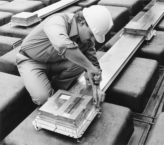
Floor structures are frequently used for the distribution of electrical and communications wiring, especially in floor areas that are broad and have few fixed partitions. If the needs for electrical and telephone service are minimal and predictable, the most economical horizontal distribution system for wiring in a floor consists of conventional conduits of metal tubing that are embedded in the floor slab or concrete topping. In most commercial buildings, however, greater flexibility is required to accommodate wiring changes that will have to occur from time to time during the life of the building. There are several alternative systems for creating this flexibility. In buildings with concrete structural systems, cellular raceways may be cast into the floor slabs (Figure 24.15). These are sheet metal ducts that can carry many wires. Working through access boxes that reach from the top of the raceway to the surface of the slab, electricians can add or remove wiring at any time. Electrical and communications outlets can be installed in any of the access boxes.
Figure 24.15 A worker levels a cellular raceway over steel dome formwork for a concrete waffle slab floor structure. The concrete will be poured so that its surface is level with the tops of the access boxes, completely embedding the raceways and allowing each box to be opened merely by removing its metal cover. Electrical and communications outlets can be installed in any access box. The covers of unused access boxes will be concealed beneath vinyl composition floor tiles or carpeting. (Courtesy of American Electric—Construction Materials Group.)
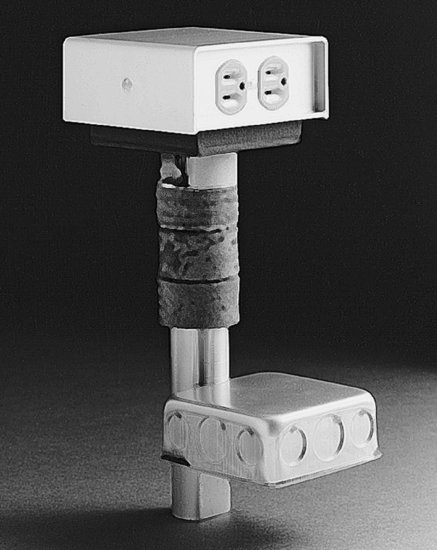
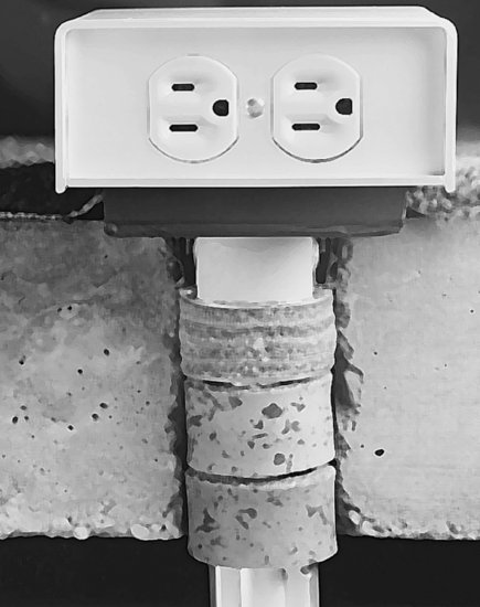
In steel-framed buildings, cellular steel decking provides the same functional advantages as cellular raceways (Figure 24.16). Poke-through fittings ( Figure 24.17) allow wiring flexibility over time without the need for raceways or cellular decking. Poke-through systems, however, require the electrician to work from the floor below the one on which changes are being made, which can be an inconvenience for the tenants of the lower floor.
Figure 24.16 Cellular steel decking is often used for underfloor electrical and communications wiring. A transverse feeder trench, near the top of the picture, brings the wiring across the floor from the electrical risers to the cells in the deck. Boxes cast into the topping give access to the cells for the installation of electrical outlets. Notice the shear studs on the steel beam at the top of the picture. (Photo courtesy of H. H. Robertson Company.)
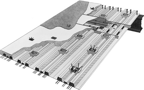
Figure 24.17 (a) A poke-through fitting is designed to be installed in a hole drilled through a concrete floor slab. The junction box at the bottom connects to a wiring conduit above the suspended ceiling of the floor below. Wires pass from the junction box through the vertical tube to the outlet above. (b) Gaskets act as firestopping to seal the hole through the slab so that fire cannot pass, thus maintaining the fire resistance rating of the floor structure. If a poke-through fitting is removed in a later renovation, a special fire-resistant abandonment plug is installed to seal the hole. (Courtesy of American Electric—Construction Materials Group.)
(a)
(b)
Raised access flooring is advantageous in buildings where wiring changes are frequent and unpredictable, such as equipment-intensive offices and dedicated server rooms (Figures 24.18 and 24.19). Raised access flooring has a virtually unlimited capability to meet future wiring needs, and changes in wiring are extremely easy to make. If the access floor is raised high enough, ductwork for air distribution can be run beneath it, possibly eliminating the need for a suspended ceiling. This can be useful in buildings where the structural system is meant to be left exposed as a finish ceiling, or in older buildings with beautiful plaster or wood ceilings. Raised access flooring also works well in older buildings because its pedestal heights can be adjusted to compensate for uneven floor surfaces. Several systems for providing individualized control of air conditioning in large office buildings utilize the space below a raised access floor as a large distribution chamber for conditioned air; each workstation is provided with a small outlet diffuser in the floor surface.
Figure 24.18 Raised access flooring provides unlimited capacity for wiring, piping, and ductwork. The space below the flooring can serve as a plenum for air distribution. Changes in any of the underfloor systems are easily made, and wiring outlets can be installed at any point in the floor. (Courtesy of Tate Architectural Products, Inc.)
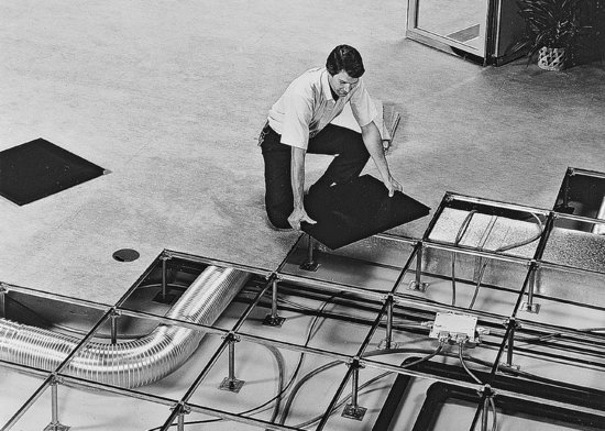
Figure 24.19 Conditioned air is supplied to this server room through the space below the raised access flooring and is fed upward through perforated floor panels. Air is returned through slots in the suspended ceiling. (Photo courtesy Armstrong World Industries.)

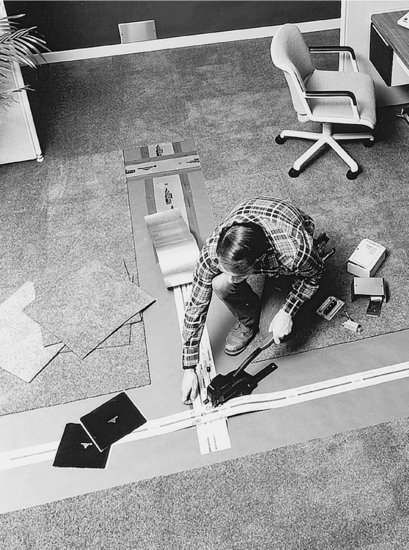
With undercarpet wiring systems, electrical power and communications wiring can be delivered within the floor system using flat conductors rather than conventional round wires installed between the finish flooring and the slab below. Undercarpet wiring is especially useful for retrofit projects where the previously discussed systems for delivering in-floor service are less practical (Figures 24.20 and 24.21).
Figure 24.20 The flat conductors for an undercarpet wiring system lie unseen beneath the carpet and are accessed through projecting boxes. (Photo: Courtesy of Burndy Corporation.)
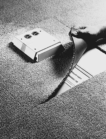
Figure 24.21 The flat conductors are ribbons of copper laminated between insulating layers of plastic sheet. These conductors are connected with the splicing tool shown in this photograph and covered with a grounded metallic shield before being taped to the floor. (Photo: Courtesy of Burndy Corporation.)
The brick floors, because the bricks may be made of diverse forms and of diverse colors by reason of the diversity of the chalks, will be very agreeable and beautiful to the eye. . . . The ceilings are also diversely made, because many take delight to have them of beautiful and well-wrought beams . . . [T]hese beams ought to be distant one from another one thickness and a half of the beam, because the ceilings appear thus very beautiful to the eye.
—Andrea Palladio, The Four Books of Architecture, 1570
TYPES OF FINISH FLOORING MATERIALS
Hard Flooring Materials
Hard finish flooring materials (concrete, stone, brick, tile, and terrazzo) are often chosen for their resistance to wear and moisture. Being rigid and unyielding, they are not comfortable to stand on for extended periods of time, and they contribute to a live, noisy acoustic environment. Many of these materials, however, are so beautiful in their colors and patterns, and so durable, that they are often considered highly desirable types by designers and building owners alike.
Concrete
With a lightly textured wood float finish for traction, concrete makes an excellent finish floor for parking garages and many types of agricultural and industrial buildings. With a smooth, hard, steel trowel finish, concrete finds its way into a vast assortment of commercial and institutional buildings, and even into homes and offices. Machine-polished concrete floors can achieve an almost glass-like level of smoothness and sheen. Color can be added with a colorant admixture, a concrete stain, or a couple of coats of floor paint. For industrial floors where hardness and durability are a special concern, concrete hardeners that densify the wearing surface of the concrete are added during slab finishing operations.
The chief advantages of concrete as a finish flooring material are its low initial cost and its durability. On the minus side, extremely good workmanship is required to make an acceptable floor finish, and, unless applied as a finish topping very close to the end of construction, even the best concrete surface is likely to sustain some damage and staining during construction.
Stone
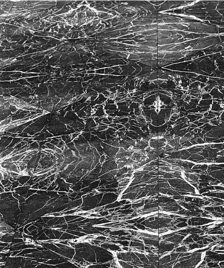
Many types of building stone are used as flooring materials, in surface textures ranging from mirror-polished marble and granite to split-face slate and sandstone (Figures 24.22 and 24.23). Installation is a relatively simple but highly skilled procedure of bedding the stone pieces in mortar and filling the joints with grout (Figure 24.24). Most stone floorings are coated with applications of a clear sealer, and are waxed periodically throughout their life building to bring out the color and figure of the stone while protecting it from stains.
Figure 24.22 A slate floor in an automobile showroom. (Photo by Bill Engdahl, Hedrich Blessing. Courtesy of Buckingham-Virginia Slate Corporation.)
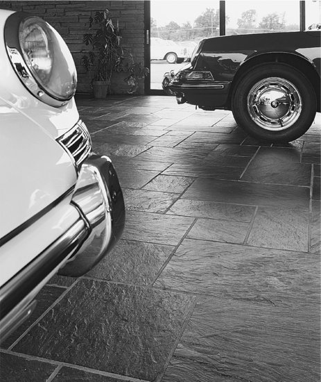
Figure 24.23 Flooring of matched, polished triangles of white-veined red marble gives a kaleidoscopic effect. (Architect: The Architects Collaborative. Photo by Edward Allen.)
Bricks and Brick Pavers
Both bricks and half-thickness bricks called pavers are used for finish flooring, with pavers often preferred because they add less thickness and dead weight to the floor (Figures 10.23, 10.24, and 24.25). Bricks may be laid with their largest surface horizontal or on edge. As with stone and tile flooring, decorative joint patterns can be designed especially for each installation.
Quarry Tiles
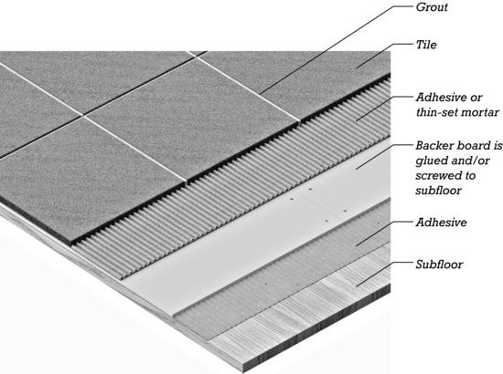
Quarry tiles are not, as might be guessed from their name, made of stone. They are simply large, fired clay tiles, usually square but sometimes rectangular, hexagonal, octagonal, or other shapes (Figures 24.24, 24.26, and 24.27). Sizes range from about 4 inches (100 mm) to 12 inches (300 mm) square, with thicknesses ranging from 3/8 inch (9 mm) to a full inch (25 mm) for some handmade tiles. Quarry tiles are available in myriad earth colors, as well as in certain kiln-applied colorations. They are usually set in a reinforced mortar bed, although in residential work they may be thin-set directly to a subfloor of wood panels or tile backer boards (Figure 24.28). (Tile-setting methods are discussed in more detail in Chapter 23.) It is important that any subfloor to which tiles are glued be sufficiently stiff; otherwise, flexing of the subfloor under changing loads will pop the tiles loose. Additional subfloor thickness and/or a stiff underlayment are advisable.
Figure 24.24 Typical details of tile, brick, stone, and terrazzo flooring. Traditional sand cushion terrazzo flooring is not illustrated. The terrazzo systems shown here are thinner and lighter than sand cushion terrazzo, but they perform as well on a properly engineered floor structure. Thin-set terrazzo, the lightest of the systems, uses very small stone chips in a mortar that is strengthened with epoxy, polyester, or polyacrylate.
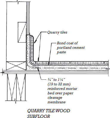
Figure 24.24 (Continued)
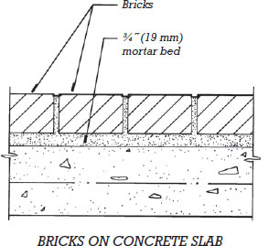
Figure 24.24 (Continued)
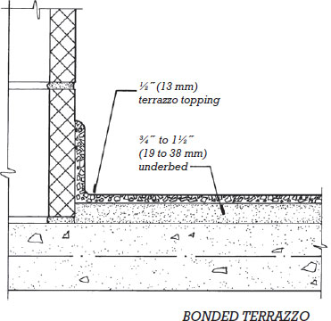
Figure 24.24 (Continued)
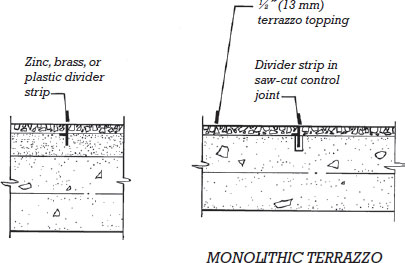
Figure 24.24 (Continued)
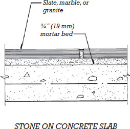
Figure 24.24 (Continued)
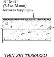
Figure 24.25 A floor of glazed brick pavers meets a planting bed constructed of brick masonry. (Courtesy of Stark Ceramics, Inc.)

Figure 24.26 Unglazed quarry tiles used as flooring and as a facing for columns and railings. (Architect: Skidmore, Owings & Merrill. Interior designer: Duffy, Inc. Courtesy of American Olean Tile.)
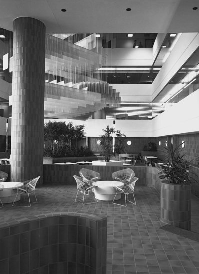
Figure 24.27 Square and rectangular quarry tiles in contrasting colors create a pattern on the floor of a retail mall. (Architect: Edward J. DeBartolo Corp. Courtesy of American Olean Tile.)
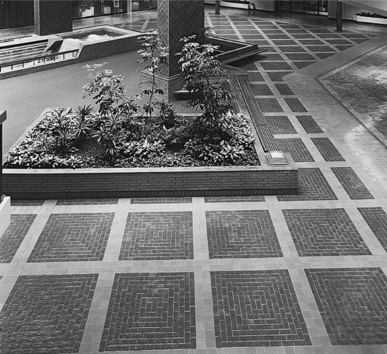
Figure 24.28 Quarry or ceramic tiles may be adhered to a cementitious backer board that is applied as an underlayment to a wood panel subfloor.
Ceramic Tiles
Fired clay tiles that are smaller than quarry tiles are referred to collectively as ceramic tiles. Ceramic tiles are usually glazed. The most common shape is square, but rectangles, hexagons, circles, and more elaborate shapes are also available (Figure 24.29). Sizes range from ½ inch (13 mm) to 4 inches (100 mm) and more. Smaller-sized tiles are shipped from the factory with their faces adhered to larger backing sheets of plastic mesh or perforated paper. The tilesetter lays whole sheets of 100 or more tiles together in a single step rather than as individual units (Figure 7.39). The backing sheet is easily removed by wetting it after the tile adhesive has cured.
Figure 24.29 Ceramic tile wainscoting and flooring in a bar. (Architect: Daughn/Salisbury, Inc. Designer: Morris Nathanson Design. Courtesy of American Olean Tile.)

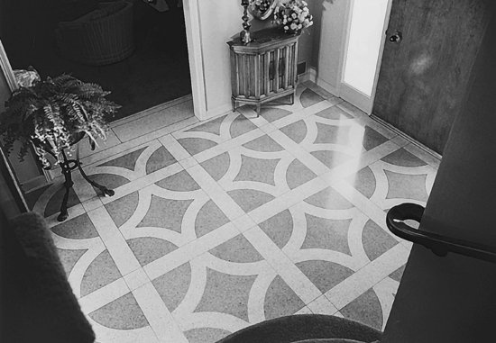
Figure 24.30 A terrazzo floor in a residential entry uses divider strips and contrasting colors to create a custom floor pattern. (Courtesy of National Terrazzo and Mosaic Association, Inc.)
Grout color has a strong influence on the appearance of tile surfaces, just as the mortar used to lay brick and stone does. Many different premixed colors are available, or the tilesetter may custom-color a grout with pigments.
Methods of installing ceramic tile on interior wall surfaces, discussed in Chapter 23, apply to floor tiling as well, and an example of ceramic tile installation on floors and walls is shown in Figure 23.40. As in wall tiling applications, waterproofing membranes are integrated into floor tile assemblies in wet-use locations. Where tile is thickset over substrates that are cracked or prone to excessive deflection, a slip sheet or cleavage membrane, usually consisting of ordinary building felt, may be inserted between the mortar base and the substrate to isolate the tile assembly and reduce the chance of tile cracking. Where tile is thin-set over difficult substrates, crack isolation membranes or uncoupling membranes that preserve the necessary bond between the thin-set compound and the substrate, but limit the transfer of stresses into the tile assembly, may be used.
Terrazzo
Terrazzo is an exceptionally durable flooring. It is made by grinding and polishing a concrete that consists of marble or granite chips selected for size and color in a matrix of colored portland cement or another binding agent. The polishing brings out the pattern and color of the stone chips. A sealer is usually applied to further enhance the appearance of the floor (Figure 24.30). Terrazzo may be formed in place or installed as factory-made tiles. For stair treads, window sills, and other large components, terrazzo is often precast. Because of its endless variety of colors and textures, terrazzo is often used in decorative flooring patterns. The colors are separated from one another by divider strips of metal, plastic, or marble. The divider strips are installed in the underbed prior to placing the terrazzo, and are ground and polished flush in the same operation as the terrazzo itself.
Traditionally, terrazzo was installed over a thin bed of sand that isolates it from the structural floor slab, thus protecting it to some extent from movements in the building frame. However, this sand cushion terrazzo is thick, usually 2½ inches (64 mm), and heavy. For greater economy and a thinner application, the sand bed is eliminated to produce bonded terrazzo, or both the sand bed and underbed may be eliminated with monolithic terrazzo. Thin-set terrazzo, made from epoxy resins, polyester resins, or polymer-modified cements, is the thinnest of all terrazzo installation methods ( Figure 24.2 4). In any of these systems, a terrazzo baseboard can be formed and finished as an integral part of the floor, thus eliminating a dirt- catching se am where the floor meets the wall.
Wood and Bamboo
Wood Flooring
Wood is used in several different forms as a finish flooring material, the most common of which is solid wood tongue-and-groove strip flooring, typically ¾ inch (19 mm) thick and 1½ to 2¼ inches (38–57 mm) wide. Strip flooring can be made from many hardwood and softwood species, some of the more commonly used being white oak, red oak, pecan, and maple (Figures 24.31, 24.32, and 24.33). The wood strips are held tightly together and blind nailed by driving nails diagonally through the upper interior corners of the tongues, where they are concealed from view once the next strip is installed. The entire floor is then sanded smooth, stained if desired, and finished with a varnish or other clear coating. When its surface becomes worn, the flooring can be restored to a new appearance by sanding and refinishing.
Figure 24.31 Details of hardwood strip flooring installation. At the left, the flooring is applied to a wood joist floor, and at the right, to wood sleepers over a concrete slab. The blind nailing of the flooring is shown only for the first several strips of flooring at the left. The baseboard makes a neat junction between the floor and the wall, covering up the rough edges of the wall material and the flooring. The three-piece baseboard shown at the left does this job somewhat better than the one-piece baseboard, but it is more expensive and elaborate. For a more stable, higher-quality installation, an additional sheet of plywood underlayment or sheathing may be added under the wood flooring in each of these examples.
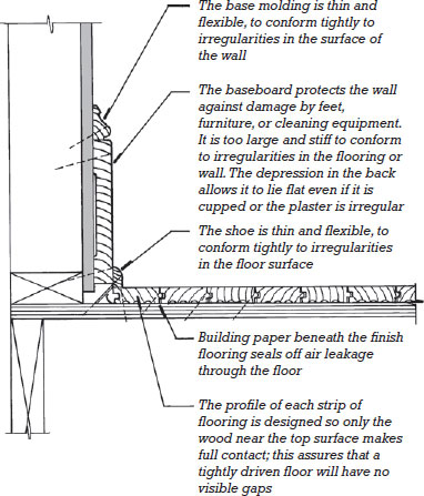
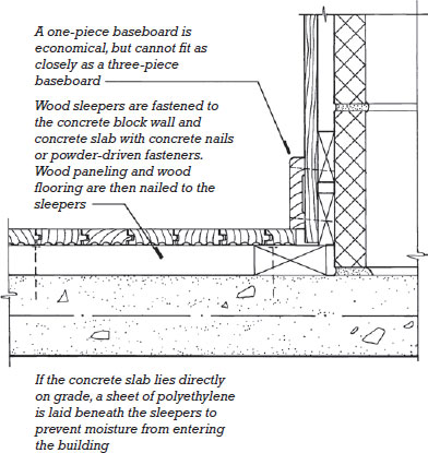
Figure 24.32 An installer of hardwood strip flooring uses a pneumatic nail gun to drive the diagonal blind nails that fasten the flooring to the subfloor. The nail gun is a special type that is activated by a blow from a mallet that also serves to drive the flooring pieces tightly together. Asphalt-saturated felt paper cushions the flooring and helps to prevent squeaking. (Photo by Rob Thallon.)
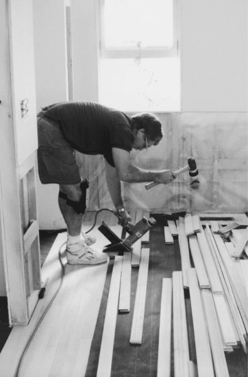
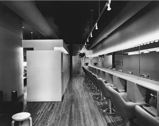
Figure 24.33 Oak strip flooring in a hair salon. Notice the use of exposed ducts and a lighting track at the ceiling. (Architects: Michael Rubin and Henry Smith-Miller in association with Kenneth Cohen. Courtesy of the Oak Flooring Institute.)
Solid wood flooring is also available in widths ranging from 3 to 8 inches (75–200 mm), called plank flooring. Because the wider planks are more prone to distortion with changes in moisture content, they are usually fastened through the face with countersunk and plugged screws in addition to, or instead of, being blind nailed along their edges.
For greater economy, factory-made wood flooring consisting of finish wood veneers laminated to a plywood-like core, called engineered wood flooring, is used. Typically 3/8 or ½ inch (10 or 13 mm) thick, it is glued to the subfloor with a mastic adhesive rather than nailed. The laminated construction of engineered wood flooring makes it less sensitive to changes in moisture content and more dimensionally stable than solid wood flooring. For this reason, it is considered better suited for use on basement slabs on grade or in other locations exposed to high humidity levels. Because the finish surface is a thin veneer, most engineered wood floorings are not able to withstand subsequent sanding and refinishing.
Parquet is wood flooring of varying hues arranged in patterns. It may be made of solid wood strips assembled in the field, of factory- preassembled blocks made from solid wood strips, or of engineered wood.
Some wood flooring systems are not nailed or glued to the subfloor, but instead “float” above it on a thin pad of resilient foam. These so-called floating floors are made by connecting the individual pieces of flooring together at the edges to make one continuous piece as large as the room in which the flooring is laid. Edge gluing is the most common way of making this connection, but systems are available that use metal clips or interlocking edge details. A gap is left at the edges to permit expansion and contraction of the floor. This is later covered with baseboard trim. Most floating floors are made of engineered wood flooring, which is more dimensionally stable than solid wood flooring.
Many types of wood flooring are available with factory-applied finishes. When the installation of conventional unfinished flooring begins on a project, it may require the complete cessation of other construction activities for a number of days while the flooring is installed and sanded, and several coats of finish are applied and allowed to dry. With factory- finished flooring, the time required for a complete installation and the impact on the other activities are minimized. Prefinished flooring, however, cannot be sanded after installation, so these products are supplied with eased edges (a slight beveling of the corners along the finish face edges) that hide minor differences in level between adjacent pieces of flooring after installation. Factory finishing is especially common with engineered wood flooring. Because the finish veneer is thin, and can never be sanded and refinished, an especially hard, wear-resistant acrylic resin finish is applied in the factory that helps to prolong the life of the floor.
Plastic laminate flooring is composed of planks or large tiles that have a wood composite core and a wearing layer of high-density plastic laminate much like that used on countertops. It is almost always laid as a floating floor. The laminate is usually patterned to resemble wood, but other patterns are also available. Most laminate floorings may be used in kitchens or baths if a sealant is applied around the perimeter of the floor to keep water from getting beneath it.
Exceptionally long-wearing industrial wood block flooring is made of small blocks of wood set in adhesive with their grain oriented vertically. Although this type of floor is relatively high in first cost, it is economical for heavily used floors and is sometimes chosen for use in public spaces because of the beauty of its pattern and grain.
Bamboo Flooring
Bamboo, a rapidly growing grass, can be used to produce flooring products very much like those of wood. The manufacturing process entails slicing the hollow bamboo shoots into strips, processing the strips to remove starch, laminating and gluing the strips under pressure, and then machining the laminated stock into the final flooring profile. Laminations may be oriented either vertically or horizontally within the strip, creating a surface appearance analogous to either flat grain or edge grain in solid woods.
Bamboo flooring is harder and more dimensionally stable than conventional wood flooring. Its natural color is light, akin to that of maple. A darker amber hue can be achieved by pressure steaming, a process called “carbonization.” Like wood, bamboo flooring can be provided either as solid strip, made entirely of bamboo laminations, or as an engineered product consisting of a roughly 1/8 -in ch (3-mm)-thick bamboo finish layer adhered to a laminated base of conventional wood. It may be provided unfinished or factory finished.
Resilient Flooring
The oldest resilient flooring material is linoleum, a sheet material made of ground cork in a linseed oil binder over a burlap backing. Asphalt tiles were later developed as an alternative to linoleum, but the majority of today's resilient sheet floorings and tiles are made of compounds of vinyl or rubber. The primary advantages of resilient floorings are the wide range of available colors and patterns, moderately high durability, and low initial cost.
Vinyl composition tile (VCT), made of one or more vinyl resins in combination with binders, pigments, and fillers (VCT may consist of as much as 85 percent limestone filler), has the lowest installed cost of any flooring material except concrete and is used in vast quantities on the floors of residences, offices, classrooms, and retail spaces. Other common resilient tile flooring materials include solid vinyl tile (SVT), with higher vinyl content and greater durability than VCT; and rubber floor tile, made from vulcanized natural or synthetic rubber compounds and various additives. Floor tile thickness is typically 1/8 inch (3 mm) or slightly less. The most common tile size is 12 inches (305 mm) square, although other sizes, up to 36 inches (914 mm) square, are also available.
The most common resilient sheet flooring materials are solid vinyl and rubber. Resilient floorings of linoleum, cork, and other materials are also available. Each offers particular characteristics of durability and appearance. Thicknesses of sheet flooring are also on the order of 1/8 inch (3 mm), slightly thinner for lighter-duty floorings, and slightly thicker if a cushioned back is added to the product. Sheet floorings are furnished in rolls 4.9 to 12 feet (1.5–3.6 m) wide. If they are skillfully installed, the seams between sheet strips are virtually invisible.
Most resilient flooring materials are glued to the concrete or wood surface of the structural floor (Figures 24.34, 24.35, and 24.36). The resilient materials themselves are so thin and deformable that they show even the slightest irregularities in the floor deck beneath. Concrete surfaces to which resilient materials will be applied must first be scraped clean of construction debris and spatters. Wood panel decks are covered with a layer of smooth underlayment panels, usually of hardboard, particleboard, or sanded plywood, to provide a smoother substrate for the resilient flooring materials. Joints between underlayment panels are offset from joints in the subfloor to eliminate soft spots. The thickness of the underlayment is chosen to make the surface of the resilient flooring level with the surfaces of flooring materials such as hardwood and ceramic tile that are used in surrounding areas of the building. Leveling compounds, gypsum or cement-based plaster-like materials that can be feathered to a very thin edge, are also used to fill in minor low spots in the floor surface before the resilient materials are installed.
Figure 24.34 Typical installation details for resilient flooring. At the top, resilient tiles applied directly to a steel-trowel-finish concrete slab, with a cove base adhered to a concrete masonry partition. To the bottom, resilient sheet flooring on underlayment and a wood joist floor structure.
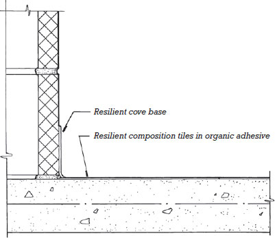
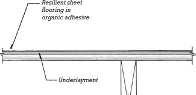
Figure 24.35 Vinyl composition tile and a vinyl cove base. Notice how the base is simply folded around the outside corner of the partition. (Photo courtesy Armstrong World Industries.)

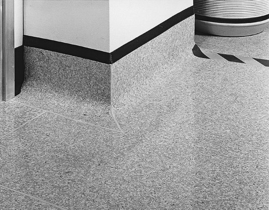
Figure 24.36 Sheet vinyl flooring can be flash coved to create an integral base that is easily cleaned, for use in health care facilities, kitchens, and bathrooms. The seams are welded to eliminate dirt-catching cracks (Photo courtesy Armstrong World Industries.)
Various flooring accessories, such as bases, stair treads, and stair nosings, are also made of vinyl and rubber compounds. Cove base is the base most commonly used with resilient flooring (Figure 24.34). Straight base, also called flat or toeless base, has no cove or toe and is most commonly used with carpet flooring. Fit-to-floor base, or butt-to base, has a square-edged toe the same thickness as the floor covering; it butts tightly to the finish flooring, creating a flush transition between the two.
Carpet
Carpet is manufactured in fibers, styles, and patterns to meet almost any flooring requirement, indoors or out, except for rooms that require thorough sanitation, such as hospital rooms, food-processing facilities, and toilet rooms. Some carpets are tough enough to wear for years in public corridors (Figure 24.37); others are soft enough for intimate residential interiors. The costs of carpeting are often competitive with those of other flooring materials of similar quality, whether they are measured on an installed-cost or life-cycle-cost basis. Slightly more than one-half of all carpet sold in North America is made with nylon fibers; more than an additional one-third is made with polypropylene; the remainder is made with other synthetics and natural fibers.
Figure 24.37 Wall-to-wall carpeting in a commercial installation (Photo courtesy Armstrong World Industries.)

There are four ways to install carpet: The two most common are gluing directly to the floor deck (direct glue-down installation ) or stretching over a carpet pad or cushion and attaching the perimeter by means of a tackless strip (stretch-in installation ). The tackless strip (also called a tackstrip ) is a continuous length of wood, fastened to the floor, that has protruding spikes along the top to catch the backing of the carpet and hold it taut as it is stretched into place by the installers. Less frequently, carpet pad is glued to the floor deck and the carpet is then glued to the pad (double glue-down installation ), or carpet with a factory-attached pad is glued to the floor deck (attached cushion installation ).
If carpet or carpet tile is laid directly over a wood panel subfloor such as plywood, the panel joints perpendicular to the floor joists should be blocked beneath to prevent movement between sheets. Tongue-and-groove plywood subflooring accomplishes the same result without blocking. Or, a layer of underlayment panels may be nailed over the subfloor with its joints offset from those in the subfloor.
Carpets, carpet pads, and adhesives are all potentially significant sources of VOC emissions. Products meeting the requirements of the Carpet & Rug Institute's Green Label Plus program are certified as meeting low-emission standards complying with current requirements of LEED NC and other green building programs. A newer standard is the NSF International's NSF/ANSI Standard 140 Sustainable Carpet Assessment Standard. NSF 140 provides a more comprehensive life-cycle rating system for carpet that addresses not only indoor air quality, but also other public health and environmental concerns, energy efficiency, recycled or biobased materials content, end-of-life reclamation, and other considerations.
Carpet Tile
Carpet materials are also manufactured in tile form, with typical sizes ranging from 18 to 36 inches (457–914 mm) square. In comparison to sheet carpet, tiles are easier to deliver, store, handle, and install; they allow easier spot replacement; they permit ready underfloor access; and they are compatible with raised-access flooring systems. Carpet tile installation methods include glue-down, in which every tile is adhered to the subfloor; partial glue-down, in which only periodically spaced tiles are adhered to the subfloor; and free-lay, in which interlocking tiles are laid without any adhesive.
Fluid-Applied Flooring
Fluid-applied flooring is applied as a thin liquid coating over concrete or wood decking and then cures to a seamless, easy-to-clean finish floor surface. Depending on formulation, coverings satisfying a wide range of requirements for durability, chemical resistance, ease of installation, and appearance are possible. Though more expensive to install than other resilient flooring options, their greater durability makes these resinous flooring systems often less expensive when costs are considered over the full life of the flooring.
Urethane and epoxy floor coatings are the most common. A typical application over concrete consists of preparation of the concrete surface by grinding or blasting, application of primer to ensure good adhesion between the substrate and the following layers, one or two coats of the primary flooring material, possibly with the addition of sand, quartz aggregate, rubber chips, or other fillers, and a top coat and/or sealer. Thickness of the finished flooring typically ranges from 3/16 to 3/8 inch (5–10 mm), although both thinner and thicker application are also possible.
Acrylic (methyl methacrylate monomer or MMA ) floor coatings, though high in VOC emissions, cure in as little as one hour. They are popular where rapid turn-around time in the floor coating process is especially important. Thin, UV-curable coatings emit no VOCs and cure virtually instantaneously as a machine with a controlled-intensity ultraviolet lamp is rolled across the wet material.
Cementitious overlays are formulations of polymers, portland cement, fine sand, and other ingredients that are applied as self-leveling fluids. Once cured, they form durable, polishable, integrally colored, finished floor surfaces.
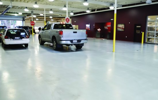
Traffic coatings are fluid-applied products, most commonly urethanes, formulated for exterior exposure, and able to tolerate both foot and vehicular traffic. They find frequent use as coatings for parking garage decks, exterior residential balconies, and elsewhere a low-cost, waterproof, and durable coating is required (Figure 24.38).
Figure 24.38 A seamless, epoxy traffic coating provides a durable, easy-to-clean, and chemical-resistant finish flooring for this automobile repair garage.
FLOORING THICKNESS
Thicknesses of floor finishes vary from 1/8 inch (3 mm) or less for resilient flooring to 3 inches (76 mm) or more for brick or stone flooring. Frequently, several different types of flooring are used on different areas of the same floor level of a building. If the differences in thickness of the flooring materials are not great, they can be resolved by using tapered edgings or thresholds at changes of material. Greater differences may be resolved with variations in the thickness of underlayment panels. Alternatively, self-leveling gypsum or cementitious underlayments can be poured up to several inches thick over portions of a subfloor to raise the level before application of the finish flooring.
If none of these solutions can satisfactorily resolve the differences, the level of the top of the floor deck must be adjusted from one part of the building to the next to bring the finish floor surfaces to the same elevation. The architect should work out the necessary level changes in advance and indicate them clearly on the construction drawings. In many cases, structural details must be drawn to indicate how the level changes should be made. In wood framing, they can usually be made either by notching the ends of the floor joists to lower the subfloor in parts of the building with thicker floor materials or by adding sheets of underlayment material of the proper thickness to areas of thinner flooring. In steel and concrete buildings, slab or topping thicknesses can change, or whole areas of the structure can be raised or lowered by the necessary amount.
KEY TERMS
REVIEW QUESTIONS
1. List the potential range of functions of a finish ceiling and of a finish floor.
2. What are the advantages and disadvantages of a suspended ceiling compared to those of a tightly attached ceiling?
3. When designing a building with its structure and mechanical equipment left exposed at the ceiling, what precautions should you take to ensure a satisfactory appearance?
4. What does underlayment do? How should it be laid? What does acoustical underlayment do?
5. List several different approaches to the problem of running electrical and communications wiring beneath a floor of a building framed with steel or concrete.
EXERCISES
1. Visit some rooms that you happen to like in nearby buildings: classrooms, auditoriums, theaters, restaurants, bars, museums, shopping centers—both new buildings and old. For each room, list the ceiling and floor finishes used. Why was each material chosen? Sketch details of critical junctions between materials. What does each room sound like—noisy, hushed, “live”? How does this acoustical quality relate to the floor and ceiling materials? What is the quality of the illumination in the room, and what role do ceiling and floor materials play in creating this quality?
2. Consult current architectural magazines for interior photographs of buildings that appeal to you. What ceiling and floor materials are used in each? Why?
SELECTED REFERENCES
Because so many ceiling and flooring materials and systems are proprietary, much of the best information on ceiling and floor finishes is to be found in manufacturers' literature. Certain generic products are, however, well documented in trade association literature:
Carpet and Rug Institute. Carpet Installation Standard. Dalton, GA, Author, updated regularly.
Industry-standard recommendations for the installation of carpet of all types, available from this association's web site as free downloads.
Ceilings and Interior Systems Construction Association. Ceiling Systems Handbook. St. Charles, IL, Author, updated frequently.
Aimed at construction workers, this manual covers everything pertaining to the installation of ceilings.
Marble Institute of America. Dimension Stone Design Manual. Cleveland, OH, Author, updated regularly.
This binder provides comprehensive guidance on the design, specification, and installation of all types of stone flooring.
National Wood Flooring Association. Installation Guidelines. Chesterfield, MO, Author, updated regularly.
This manual provides industry standard recommendations for the installation of all kinds of wood flooring.
Tile Council of North America, Inc. TCNA Handbook for Ceramic Tile, Glass, and Stone Tile Installation. Anderson, SC, Author, updated regularly.
This is the definitive standard for ceramic tile installation materials and methods. More than 100 methods of installation for floors and walls, both interior and exterior, are illustrated and specified. Guidelines for selecting appropriate installation methods based on project requirements are also included.
WEB SITES
Author's supplementary web site: www.ianosbackfill.com/24_finish_ceilings_and_floors
Armstrong Floors and Ceilings: www.armstrong.com
Carpet and Rug Institute (CRI): www.carpet-rug.org
Ceilings and Interior Systems Construction Association: www.cisca.org
Forbo Floor Coverings: www.forbo-flooring.us
H. H. Robertson: www.hhrobertson.com
Mannington Floors: www.mannington.com
Maple Flooring Manufacturers Association (MFMA): www.maplefloor.org
Marble Institute of America (MIA): www.marble-institute.com
National Terrazzo & Mosaic Association (NTMA): www.ntma.com
National Wood Flooring Association (NWFA): www.nwfa.org
Resilient Floor Covering Institute (RFI): www.rfci.com
Tile Council of North America (TCNA): www.tcnatile.com