Chapter 7
Modeling with Primary Features
This chapter helps you identify which features to use in which situations—and in some cases, which features to avoid. It also helps you evaluate which feature is best to use for a particular job. With some features, it is clear when to use them, but not for others. This chapter guides you through the decision-making process. I have split the list of SolidWorks features into two groups: primary features and secondary features. Primary features are, of course, the ones you use most frequently.
Identifying When to Use Which Tool
I always try to think of alternative ways to do things. It is important to have a backup plan—or sometimes multiple backup plans—in case a feature doesn't perform exactly the way you want it to perform. As an exercise, I often try to see how many different ways a particular shape might be modeled and how each modeling method relates to manufacturing methods, costs, editability, efficiency, and so on. You may also want to try this approach for fun or for education. If you are familiar only with the standard half dozen or so most-used features, your options are limited. Sometimes, simple features truly are the correct ones to use, but using them because they are the only things you know is not always the best approach.
Using the Extrude Feature
 Extruded features can be grouped into several categories, with extruded Boss and Cut features at the highest level. You can extrude closed-loop sketches, regions, and, in some cases, faces. You can extrude from a face, an offset, or a plane. Extrude features can also be made in one direction, two directions, or as a midplane. Draft is also an option with Extrude features.
CREATING A SOLID FEATURE
In this case, the term solid feature is used as an opposite of thin feature. A solid feature is the default when you extrude a closed-loop sketch. A closed-loop sketch fully encloses an area without gaps or overlaps at the sketch entity endpoints. Figure 7.1 shows a closed-loop sketch creating an extruded solid feature.
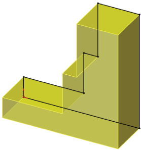
FIGURE 7.1 A closed-loop sketch and an extruded solid feature
CREATING A THIN FEATURE
The Thin Feature option is available in several features, but it's most commonly used with Extruded Boss features. Thin features are created by default when you use open-loop sketches, but you can also select the Thin Feature option for closed-loop sketches or sketches with mixed types. Thin features are commonly used for ribs, thin walls, hollow bosses, and many other types of features that are common to plastic parts, castings, or sheet metal.
Even experienced users tend to forget that thin features are not just for bosses, but that they can also be used for cuts. For example, you can easily create grooves and slots with Thin Feature cuts.
Figure 7.2 shows thin features. In addition to the default options that are available for the Extrude feature, the Thin feature adds a thickness dimension, as well as three options to direct the thickness relative to the sketch: One-Direction, Mid-Plane, and Two-Direction. The Two-Direction option requires two dimensions.
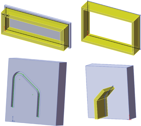
FIGURE 7.2 Different types of geometry created from Thin Feature extrudes
You can create a cube from a single sketch line and a Thin Feature extrude. However, because they are more specialized in some respects, thin features may not be as flexible when the design intent changes. For example, if a part is going to change from a constant width to a tapered or stepped shape, thin features will not handle this kind of change. Figure 7.2 shows different types of geometry that are typically created from thin features.
UNDERSTANDING THE WORKFLOW
SolidWorks offers multiple ways to do things in most functions. Most of the time, there is no one way that is better than the others. Having a lot of ways to do things makes remembering ways to do things easy, but sometimes it is hard to teach or learn because the options get overwhelming quickly. My suggestion is to find a way that works for you and use it. Learn other ways if something stops working for you. Here's an example.
The Extrude Feature workflow offers several options:
- From within an active sketch with appropriate geometry, click the Extrude toolbar icon.
- Set the Extrude Feature options.
- Click OK.
Or:
- With no sketch active, click the Extrude toolbar icon.
- Select an existing sketch with appropriate geometry.
- Set the Extrude Feature options.
- Click OK.
Or:
- With no sketch active, click the Extrude toolbar icon.
- Select a plane on which to create a sketch to extrude.
- Create your sketch.
- Exit the sketch using the Confirmation Corner icon.
- Set the Extrude Feature options.
- Click OK.
Different types of features and geometry require different types of sketches, as shown in Figure 7.3. Some sketch types can't be used directly for making features at all, but may be used as reference. Closed, Open, and Nested contours are the types you will probably use the most in SolidWorks.
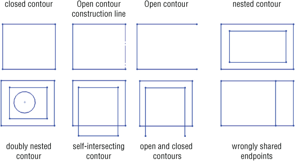
FIGURE 7.3 Sketch types
In addition to extruding 2D sketches, SolidWorks can also extrude 3D sketches. SolidWorks will automatically fill in the 3D sketch to form a solid face. You need to define a direction such as a plane (the plane normal is used as direction) or an edge, line, or axis, as shown in Figure 7.4.
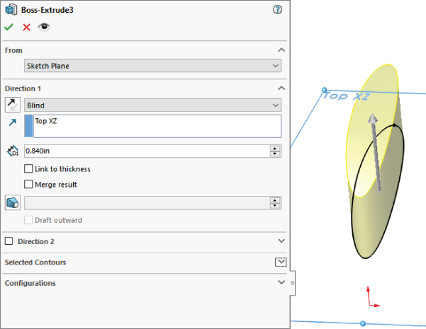
FIGURE 7.4 Extruding from a 3D sketch
USING END CONDITIONS
End conditions control how the extrude starts and stops. In most situations, the extrude starts from a sketch plane and goes a specified distance, but there are other options.
Start conditions
- From sketch plane
- From offset distance/vertex
- From selected plane
- From 3D sketch
- From selected face
End conditions
- Distance (blind)
- Through all (up to the furthest face)
- Up to a selected vertex
- Up to a selected surface
- Offset from surface (either near or far offset, and either offset or translated)
- Up to a selected body
- Midplane (divides distance in half about start plane)
Direction
- In addition to the start and end conditions, you can control the direction of the extrude.
- If you want to push a profile along a curve, you can use either a revolve or a sweep, as appropriate, which are both covered later in this chapter.
Understanding Instant 3D
 Instant 3D is the tool that enables you to use the mouse to pull arrows or handles on the screen to change various dimension parameters for features such as Extrude, Revolve, Fillet, and even Move Face. Not every dimension parameter is editable in this way. In some cases, Instant 3D offers you convenient ways to edit geometry without needing to figure out which feature is responsible for which faces. With Instant 3D, you simply pull on handles on the screen to move and resize sketches and features including fillets.
To me, Instant 3D is a gimmick that tries to imitate direct-edit software without the actual benefits of direct-edit software. If you want direct-edit software, you will need to get different software. The usefulness of Instant3D is probably limited to concept modeling, or quick looks-like models. I just want to make sure that no one confuses Instant3D with actual direct editing, as the SolidWorks marketing seems to try to do.
Working with the Revolve Feature
 Like all other features, Revolve features have some rules that you must observe when choosing sketches to create a revolve:
- You can use any type of line or model edge for the centerline, not just the centerline/construction line type.
- If there is only one actual center/construction line in the sketch, it will automatically be used as the axis of revolution.
- Draw only half of the revolve profile. Draw the section to one side of the centerline.
- The profile must not cross the centerline.
- The profile must not touch the centerline at a single point. It can touch along a line but not at a point. Revolving a sketch that touched the centerline at a single point would create a point of zero thickness in the part.
UNDERSTANDING END CONDITIONS
There are five Revolve end conditions:
- Blind
- Up To Vertex
- Up To Surface
- Offset From Surface
- Midplane
There is no equivalent for Up To Next or Up To Body with the Revolve feature. Figure 7.5 shows the Revolve PropertyManager.
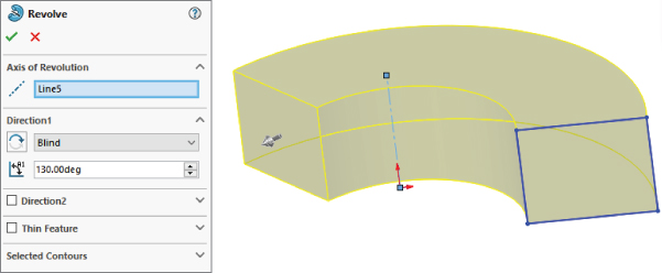
FIGURE 7.5 Using the Revolve PropertyManager
WORKFLOW
This is the workflow for the Revolve feature:
- Create a sketch.
- Invoke the Revolve feature.
- Select an axis (typically a construction line).
- Set the end conditions.
- Click OK.
USING CONTOUR SELECTION
Like Extrude features, Revolve features can also use contour selection, and as with the Extrude features, I recommend that you avoid using contours for production work.
Introducing Loft, Boundary, and Sweep
 Sweep, loft, and boundary are known as interpolated features. This means that you can create profiles for the feature at certain points, and the software interpolates the shape between the profiles. You can use additional controls with loft, such as guide curves or centerlines, and establish end conditions to help direct the shape. A loft with just two profiles is a straight-line transition. If you have more than two profiles, the transition from one profile to another works more like a spline.
Many users struggle when faced with the option to create a loft, boundary, or sweep. Some overlap exists among the three features, but as you gain some experience, it becomes easier to choose among them. Generally, if you can create the cross section of the feature by manipulating the dimensions of a single sketch, a sweep might be the best feature. If the cross section changes character or severely changes shape, loft or boundary may be best. If you need a very definite shape at both ends and/or in the middle, loft and boundary are better choices because they enable you to explicitly define the cross section at any point. However, if the outline is more important than the cross section, you should choose a sweep. In addition, if the path between ends is important, choose a sweep.
Both types of features are extremely powerful, but the sweep has a tendency to be fussier about details, setup, and rules, although the loft and boundary can be surprisingly flexible. I am not trying to dissuade you from using sweeps, because they are useful in many situations. However, in my own modeling, I probably use about 10 lofts or boundary features for every sweep. For example, although you would use a loft or combination of Loft features to create the outer faces of a complex laundry detergent bottle, you would use the sweep to create a raised border around the label area or the cap thread.
A good example of the interpolated nature of a loft is to put a circle on one plane and a rectangle on an offset plane and then loft them together. This arrangement is shown in Figure 7.6. The transition between shapes is the defining characteristic of a loft and is the reason for choosing a loft instead of another feature type. Lofts can create both Boss features and Cut features.
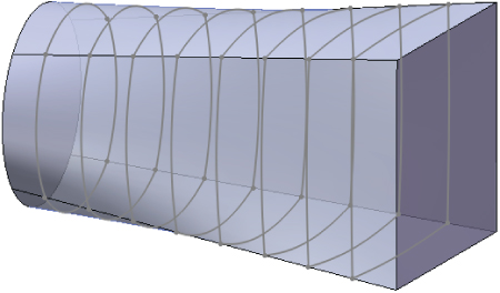
FIGURE 7.6 Interpolation inside a loft
Notice how the cross-sectional shape of the loft transitions from the circle to the rectangle. The default setting (refer to Figure 7.6) is for the interpolated transition to happen evenly across the loft, but the distribution of change from one end to the other could be altered, which might result in the transitions shown in Figure 7.7.
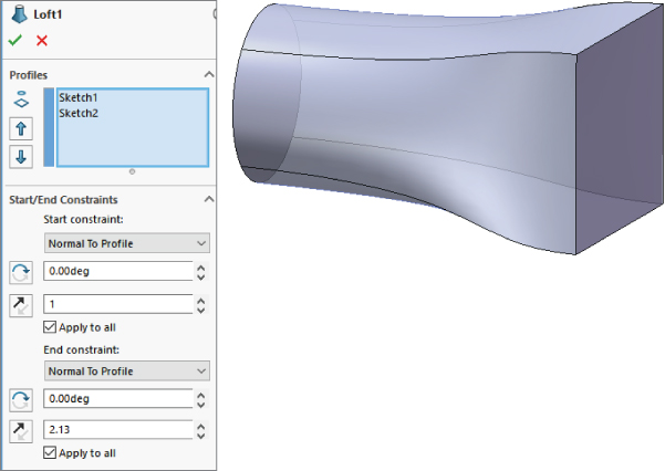
FIGURE 7.7 Adding end conditions to a loft alters how the interpolation is distributed.
Both shapes are two-profile lofts. The two-profile loft with default end conditions always creates a straight transition, which is shown in the Figure 7.6. A two-point spline with no end tangency creates a straight line in exactly the same way. By applying end conditions to either or both of the loft profiles, the loft's shape is made more interesting, as shown in Figure 7.7. Again, the same thing happens when applying end tangency conditions to a two-point spline: It goes from being a straight line to being more curvaceous, with continuously variable curvature.
COMPARING THE LOFT AND BOUNDARY FEATURES
 An important difference between boundary and loft is that there are more options for setting up Boundary features in terms of the geometrical layout of profiles and guide curves. A second major difference is that there are no profiles and guide curves in boundary—the two directions are treated equally, and they are simply called Direction 1 and Direction 2. In the Loft feature, you don't have as much continuity control across the guide curve direction. This is less meaningful with solid features than with surfaces. In fact, the Boundary feature is used far less often than its surfacing-related cousin, the Boundary Surface.
The geometrical layout of profiles is the most important difference between boundary and loft. With loft, you must have a profile at the beginning and end of the feature. With boundary, you can lay out the profile sketch planes like an X. You could also lay the feature out like a T, which would act like a sweep. Using a layout shaped like an F actually combines the functionality of a loft with that of a sweep. Boundary is a very powerful feature, with options for creating interpolated solid shapes. Face-by-face control, however, still must come from using surfacing features.
Figure 7.8 shows the features made with F and X layouts of sketches. The F layout resembles the letter F, and the sketches lie on the planes Right YZ, FrontXY, and Plane1. The X layout uses sketches on RightYZ and Plane2. These two features represent sketch layouts that you can't use with the Loft feature.
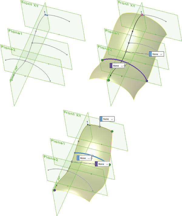
FIGURE 7.8 Using different profile arrangements for Boundary solid features
Loft does have two conditions that Boundary cannot answer:
- Centerline loft: All boundary profiles must intersect.
- Closed loop loft without Direction 2 (guide) curves: To make a closed-loop boundary, you must have Direction 2 curves that intersect Direction 1 curves.
USING ENTITIES IN A LOFT
For solid lofts, you can select faces, closed-loop 2D or 3D sketches, and surface bodies. You can use sketch points as a profile on the end of a loft that comes to a point or rounded end. For surface lofts, you can use open sketches and edges in addition to the entities that are used by solid lofts, but you cannot combine open and closed contours.
Some special functionality becomes available to you if you put all the profiles and guide curves together in a single 3D sketch. In order to select profiles made in this way, you must use the SelectionManager, which is discussed later in this chapter.
The Sketch Tools panel of the Loft PropertyManager enables you to drag sketch entities of any profile made in this way while you are editing or creating the Loft feature, without needing to exit and edit a sketch.
I discuss 3D sketches in more detail in Chapter 6, “Getting More from Your Sketches.”
COMPARING LOFTS AND SPLINES
The words loft and spline come from the shipbuilding trade. The word spline is actually defined as the slats of wood that cover the ship, and the ribs of the hull very much resemble loft sections. With the splines or slats bending at each rib, it is easy to see how the modern CAD analogy came to be.
Lofts and splines are also governed by similar mathematics. You have seen how the two-point spline and two-profile loft both create a straight-line transition. Next, a third profile is added to the loft and a third point to the spline, which demonstrates how the math that governs splines and lofts is also related to bending in elastic materials. Figure 7.9 shows how lofts and splines react geometrically in the same way that bending a flexible steel rod would react (except that the spline and the loft do not have a fixed length).
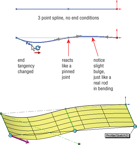
FIGURE 7.9 Splines, lofts, and bending
With this bit of background, it is time to move forward and talk about a few of the major aspects of Loft features in SolidWorks. In this single chapter, I do not have the space to cover the topic exhaustively, but coverage of the major concepts will be enough to point you in the right direction.
Controlling Sweep Features
 The Sweep feature generally uses multiple sketches. A sweep is made from a profile (cross section) and a path, and it can create a Boss or a Cut feature. If you want, you can also use guide curves. Sweeps can run the gamut from simple to complex. Typical simple sweeps are used to create wire, tubing, or hose. Sweeps that are more complex are used for creating objects such as bottles, involutes, springs, and corkscrews.
The main criterion for selecting a sweep to create a feature is that you must be able to identify a cross section and a path. The profile (cross section) can change along the path, but the overall shape must remain the same. The profile is typically perpendicular to the path, although this is not a requirement.
A recent addition to the software includes an option in the Sweep PropertyManager for a Circular Profile. This is for simple sweeps with a circle driven along a path by its center, maintaining a constant diameter (such as wire, hose, pipe, and so on). To use this function, specify the diameter of the circle in the PropertyManager.
USING A SIMPLE SWEEP
An example of a simple sweep is shown in Figure 7.10. The paper clip uses a circle as the profile and the coiled lines and arcs as the path. Simple sweeps keep the same size and shape profile along the entire path. This sweep could use the previously mentioned option for Circular Profile, also shown in Figure 7.10.
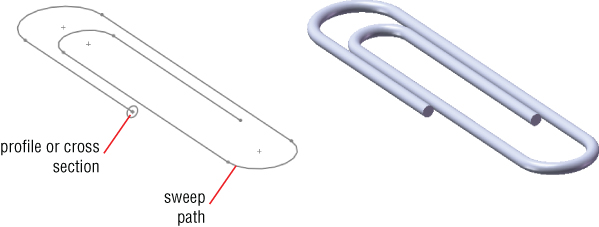
FIGURE 7.10 The Sweep Profile follows the path.
USING A SWEEP WITH GUIDE CURVES
Sweeps that are more complex begin to control the size, orientation, and position of the cross section as it travels through the sweep. When you use a guide curve, several analogies can be used to visualize how the sweep works. The cross section/profile is solved at several intermediate positions along the path. If the guide curve does not follow the path, the difference between the two is made up by adjusting the profile. Consider the following example. In this case, the profile is an ellipse, the path is a straight line, and there are guide curves that give the feature its outer shape. Figure 7.11 shows all these elements and the finished feature.
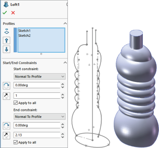
FIGURE 7.11 The sweep profile follows the path and is controlled parametrically by guide curves.
The PropertyManager for the Sweep function includes an option for Show Sections, which in this case creates almost 200 intermediate cross sections. These sections are used behind the scenes to create a loft. You can think of complex sweeps with guide curves or centerlines as an automated setup for an even more complex loft. It is helpful to envision features such as this when you are troubleshooting or setting up sweeps that are more complex. Once you open the Chapter7 Bottle.sldprt part, you can edit the Sweep feature to examine the sections for yourself.
In most other published SolidWorks materials that cover these topics, sweeps are covered before lofts because many people consider lofts the more advanced topic. However, I have put lofts first because understanding them is necessary before you can understand complex sweeps, because complex sweeps really are just lofts.
USING A PIERCE RELATION
The Pierce sketch relation is the only sketch relation that applies to a 3D out-of-plane edge or curve without projecting the edge or curve into the sketch plane. It acts as if the 3D curve is a length of string and the sketch point is the hole in the center of a bead. The Pierce relation is most important in the Sweep feature when it is applied in the profile sketch between endpoints, centerpoints, or sketch points and the out-of-plane guide curves. This is because the Pierce relation determines how the profile sketch will be solved when it is moved down the sweep path to create intermediate profiles.
Figure 7.12 illustrates the function of the Pierce relation in a sweep with guide curves. The dark section on the left is the sweep section that is sketched. The lighter sketches to the right represent the intermediate profiles that are automatically created behind the scenes and are used internally to create the loft.
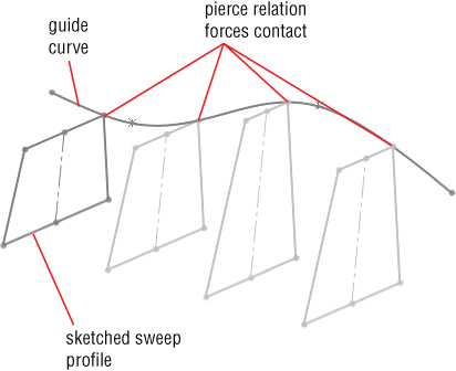
FIGURE 7.12 The effects of the Pierce relation
Figure 7.12 shows what is happening behind the scenes in a Sweep feature. The sweep re-creates the original profile at various points along the path. The guide curve in this case forces the profile to rebuild with a different shape. Pierce constraints are not required in simple sweeps, but when you start using guide curves, you should also use a Pierce.
Figure 7.13 shows a more complicated 3D sweep, where both the path and the guide curve are 3D curves. I cover 3D curves in Chapter 8, “Selecting Secondary Features”; you can refer to these sections to understand how this part is made.

FIGURE 7.13 A 3D sweep
This part is created by making a pair of tapered helices, with the profile sketch plane perpendicular to the end of one of the curves. The taper on the outer helix is greater than on the inner one, which causes the twist to become larger in diameter as it goes up.
To make the circle follow both helices, you must create two Pierce relations, one between the center of the circle and a helix, and the other between a sketch point that is placed on the circumference of the circle and the other helix. This means that the difference in taper angles between the two helices is what drives the change in diameter of the sweep.
USING A CUT SWEEP WITH A SOLID PROFILE
The Cut Sweep feature has an option to use a solid sweep profile. This kind of functionality has many uses, but it's primarily intended for simulating complex cuts made by a mill or lathe. Figure 7.14 shows a couple of examples of cuts you can make with this feature. The part used for this screen shot, called Chapter 7 - cut sweep solid profile.sldprt, is also in the website download material.
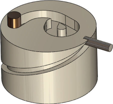
FIGURE 7.14 Cuts you can make with the Cut Sweep feature using a solid profile
The solid profile cut sweep has a few limitations that I need to mention:
- It requires two bodies: the target and a cutting tool.
- The path must start at a point where it intersects the solid cutting tool body (path starts inside or on the surface of the cutting tool).
- The path must be tangent within itself (no sharp corners).
- The cutting tool must be definable with a revolved feature.
- The cutting tool must be made of simple analytical faces (sphere, torus, cylinder, and cone; no splines).
- You cannot use a guide curve with a solid profile cut (because you cannot control alignment).
- The cut can intersect itself, but the path cannot cross itself.
You can create many useful shapes with the solid-profile-cut sweep, but because of some of the limitations I've listed, some shapes are more difficult to create than others. For these shapes, you might choose to use regular Cut Sweep features.
WORKFLOW
Use the following general steps to create Sweep features:
- Create the path first. It may be tempting to create the profile first, but as a general rule, things work out better if you make the path first.
- Create guide curves. Again, these work out better if you create them before the profile.
- Create the profile (sweep cross section) and relate it to the path with a Pierce sketch relation. Select a point in the sweep profile that you want to be driven down the path, as a bead follows a string.
- Make sure that, as the profile is driven down the path (with the profile sketch plane maintaining its original relationship with the path), the profile has the flexibility to change the way it needs to change. The sketch is reevaluated at each point along the path. Use relative relations (parallel, perpendicular, and so on) instead of absolute ones (horizontal, vertical, or fixed).
- Start the Sweep feature from the toolbar or menu. All sketches must be closed.
- Select the profile first and then the path. SolidWorks automatically toggles from the profile selection box to the path selection box as soon as a profile is selected, so take advantage of this automation to help you work quickly. Note that for circular profiles centered on the path, there is no longer a need to create a sketch.
- Use the preview to check that it is performing the way you want. Click OK when you are satisfied with the result.
Understanding Fillet Types
SolidWorks offers very powerful filleting functions. The Fillet feature comprises various types of fillets and blends. Simple fillets on straight and round edges are handled differently from variable-radius fillets, which are handled differently from the single or double hold-line fillet or setback fillets. After you click the OK button to create a fillet as a certain type, you cannot switch it to another type. You can switch types only before you actually create the feature.
Many filleting options are available, but most of them are seldom used or even known. In fact, most users confine themselves to the constant-radius or variable-radius fillets. This section describes all the available fillet types and options:
- Constant-size fillet
- Symmetric fillet
- Circular
- Conic rho
- Conic radius
- Curvature continuous
- Asymmetric fillet
- Elliptic
- Conic rho
- Curvature continuous
- Multiple-radius fillet
- Round corners
- Keep edge/Keep surface
- Keep feature
- Symmetric fillet
- Variable-size fillet
- Face fillet
- Curvature-continuous fillet
- Face fillet with Help Point
- Single hold-line fillet
- Double hold-line fillet
- Constant-width fillet
- Full round fillet
- Setback fillet
- Setback fillet with variable radius
Figure 7.15 shows the Fillet PropertyManager.
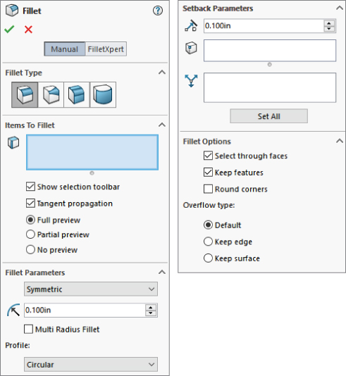
FIGURE 7.15 The Fillet PropertyManager
Note that SolidWorks does not distinguish between fillets and rounds, and even two edges that are selected for use with the same Fillet feature can have opposite functions—for example, both adding and removing material in a single feature.
Creating a Constant-Size Fillet
Constant-size fillets are the most common type that are created if you select only edges, features, or faces without changing any settings. When you select features or faces that cause large numbers of fillets to be applied, you should consider several best-practice guidelines and other recommendations that come later in this chapter.
SELECTING ENTITIES TO FILLET
You can create fillets from several selections, including edges, faces, features, and loops. Edges offer the most direct method and are the easiest to control. Figure 7.16 shows how you can use each of these selections to create fillets on parts more intelligently.
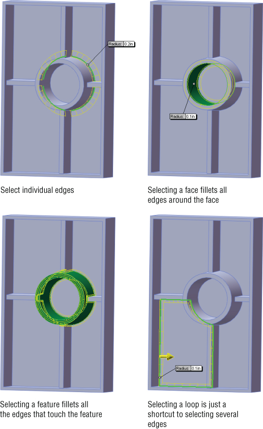
FIGURE 7.16 Selection options for fillets
Faces and features selections are useful when you are creating fillets where you want the selections to update. In Figure 7.16, the ribs that intersect the circular boss are also being filleted. If the rib did not exist when the fillet was applied but was added later and reordered so it came before the Fillet feature, then the fillet selection automatically considers the rib. If the fillet used edge selection, this automatic selection updating would not take place.
USING TANGENT PROPAGATION
By default, fillets have the Tangent Propagation option turned on. This is usually a good choice, although there may be times when you want to experiment with turning it off. Tangent propagation simply means that if you select an edge to fillet, and this edge is tangent to other edges, then the fillet keeps going along tangent edges until it forms a closed loop, the tangent edges stop, or the fillet fails.
If you deselect Tangent Propagation, but there are still tangent edges, you may see different results. One possible result is that it could fail. One of the tricks with Fillet features is to try to envision what you are asking the software to do. For example, if one edge is filleted and the next edge is not, then how is the fillet going to end? Figure 7.17 shows two of the potential results when fillets are asked not to propagate. The fillet face may continue along its path until it runs off the part or until the feature fails.
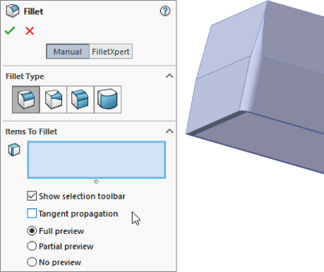
FIGURE 7.17 Deselecting the Tangent Propagation option
DEALING WITH A LARGE NUMBER OF FILLETS
Figure 7.18 shows a model with a bit of a filleting nightmare. This large plastic tray requires many ribs underneath for strength. Because the ribs may be touched by the user, the sharp edges need to be rounded. Interior edges also need to be rounded for strength and plastic flow through the ribs. Literally, hundreds of edges will need to be selected to create the fillets if you do not use an advanced technique.
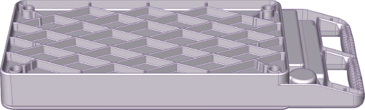
FIGURE 7.18 A plastic tray with a large number of fillets
SELECTING ENTITIES
Some of the techniques outlined previously, such as face and feature selection, can be useful for quickly filleting a large number of edges that all meet the same criteria. Another method is window selection of the edges. To use this option effectively, you may want to first position the model into a view where only the correct edges will be selected, turn off the Select Through Faces option, and use the Edges selection filter.
The first option in the Fillet PropertyManager is the Selection toolbar. This toolbar highlights several selection options based on types of selections similar to your initial selection. For example, if you selected an edge, the Selection toolbar might highlight edges parallel to the selected edge, faces that touch the selected edge, or edges tangent to the selected edge.
USING THE FILLETXPERT
The FilletXpert automatically finds solutions to complex fillet problems, particularly the problems that can arise when you have several fillets of different sizes coming together. It also allows you to select multiple edges. A part like the one shown in Figure 7.18 is ideal for this tool.
To use the FilletXpert, click the FilletXpert button in the Fillet PropertyManager (Figure 7.19). When you select an edge, the FilletXpert presents a pop-up toolbar, giving you several selection options. Notice that Figure 7.19 shows the majority of the edges selected that are needed for this fillet. This is the same type of functionality you will find in the Selection toolbar, in fact; the Selection Toolbar toggle is found in the FilletXpert PropertyManager shown in Figure 7.19.

FIGURE 7.19 Using the FilletXpert selection technique and the Selection toolbar
The Corner tab of the FilletXpert enables you to select from different corner options, which are usually the result of different fillet orders. To use the CornerXpert, make sure the FilletXpert is active, then click the corner face, and toggle through the options.
USING PREVIEW
I like to use the fillet preview. It helps to see what the fillet will look like, and perhaps more important, the presence of a preview usually (but not always) means that the fillet will work.
Unfortunately, when you have a large number of fillets to create, the preview can cause a significant slowdown. Deselecting and using the partial preview are both possible options. Partial preview shows the fillet on only one edge in the selection and is much faster when you are creating a large number of fillets.
USING FOLDERS
When you have a large number of Fillet features, it can be tedious to navigate the FeatureManager. Therefore, it is useful to place groups of fillets into folders. This makes it easy to suppress or unsuppress all the fillets in the folder at once. Separate folders can be particularly useful if the fillets have different uses, such as fillets that are used for PhotoWorks models and fillets that are removed for FEA (Finite Element Analysis) or drawings. Folders also allow the bulk-selection of such features if they were saved in selection sets.
MAKING MULTIPLE FILLET SIZES
The Multiple Radius Fillet option in the Fillet PropertyManager enables you to make multiple fillet sizes within a single Fillet feature. Figure 7.20 shows how the Multiple Radius Fillet feature looks when you are working with it. You can change values in the callout flags or in the PropertyManager.
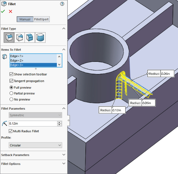
FIGURE 7.20 Using the Multiple Radius Fillet option
Although you may see a small performance benefit when condensing several features into one, many more downsides adversely affect performance:
- You lose control of feature order.
- A single failed fillet causes the whole feature, and therefore all the fillets, to fail.
- Troubleshooting is far more difficult.
- Smaller groups of fillets cannot be suppressed without suppressing everything.
- You cannot change the size of a group of fillets together.
ROUNDING CORNERS
The Round Corners option refers to how SolidWorks handles fillets that go around sharp corners. By default, this setting is off, which leaves fillets around sharp corners looking like mitered picture frames. If you turn this setting on, the corner looks like a marble has rolled around it. Figure 7.21 shows the resulting geometry from both settings.
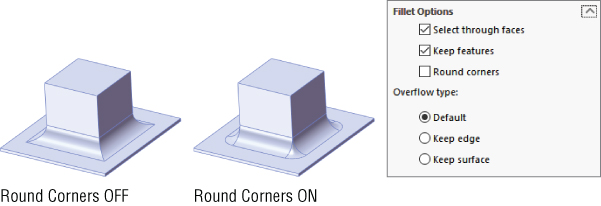
FIGURE 7.21 The Round Corners option, both on and off
USING THE KEEP EDGE/KEEP SURFACE TOGGLE
The Keep Edge/Keep Surface toggle determines what SolidWorks should do if a fillet is too big to fit in an area. The Keep Edge option keeps the edge where it is and tweaks the position (not the radius) of the fillet to make it meet the edge. The Keep Surface option keeps the surfaces of the fillet and the end face clean; however, to do this, it has to tweak the edge. There is often a tradeoff when you try to place fillets into a space that is too small. Sometimes, it is useful to visualize what you think the result should look like. Figure 7.22 shows how the fillet would look in a perfect world, followed by how the fillet looks when cramped with the Keep Edge option and how it looks when cramped with the Keep Surface option.
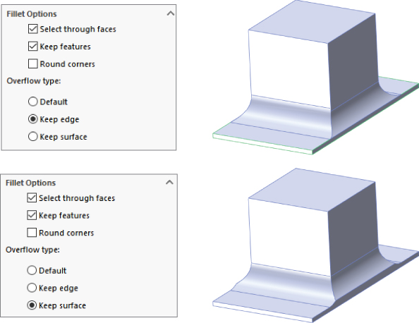
FIGURE 7.22 The Keep Edge option and the Keep Surface option
The Default option chooses the best option for a particular situation. As a result, it seems to use the Keep Edge option unless it does not work, in which case it changes to the Keep Surface option.
USING THE KEEP FEATURE OPTION
The Keep Feature option appears on the Fillet Options panel of the Fillet PropertyManager. By default, this option is turned on. If a fillet surrounds a feature such as a hole (as long as it is not a through hole) or a boss, then deselecting the Keep Feature option removes the hole or boss. When Keep Feature is selected, the faces of the feature trim or extend to match the fillet, as shown in Figure 7.23.
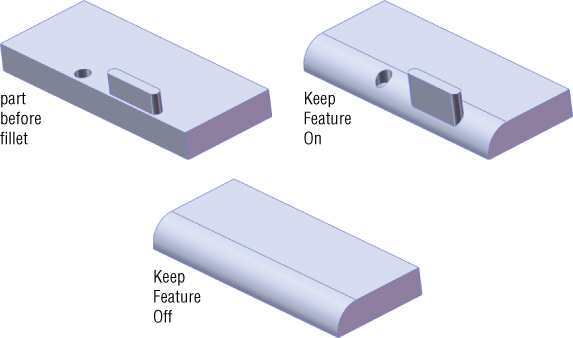
FIGURE 7.23 The Keep Feature option, both selected and unselected
USING SYMMETRIC OR ASYMMETRIC FILLETS
Standard fillets are symmetrical on either side of the selected edge. An asymmetrical fillet can have a different radius on either side of the selected edge. This makes for a more complex-looking fillet and may also complicate troubleshooting in complex parts. Figure 7.24 illustrates the concept of asymmetrical fillets, along with the Fillet Parameters panel of the Fillet PropertyManager associated with specifying this type of fillet.

FIGURE 7.24 Asymmetrical fillets
 Asymmetrical fillets can also be used in variable-radius fillets, described later in this chapter. In addition to specifying the two radius values, you can also flip the sides of the values using the opposing arrows icon.
SELECTING A FILLET PROFILE
Within the Symmetric and Asymmetric fillets, you also have some profile options:
- Circular (only symmetric)
- Elliptic (only asymmetric)
- Conic rho (symmetric and asymmetric)
- Conic radius (only symmetric)
- Curvature continuous (symmetric and asymmetric)
You can think of these profiles as being the fillet cross sections. Circular cross sections can be defined with a single radius. This should make intuitive sense. You should also be familiar with the shape of an ellipse, although this is not directly specifiable with a radius value, SolidWorks uses the radius value to approximate. The cross sections are shown in Figure 7.25.
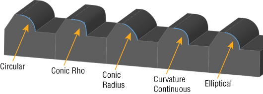
FIGURE 7.25 Fillet profiles change the shapes of the filleted edges.
The Circular profile is the normal type of fillet specified with a single radius. This is what we think of as a default fillet.
The Elliptic profile is available only when specifying asymmetric fillets. The two radius values determine an ellipse, which is used to round the selected edge instead of the usual arc.
The Conic rho profile is driven by rho (ρ). Conic in the name refers to the conic sections from classical geometry–circle, ellipse, hyperbola, parabola—but as driven by the parameter rho in many other CAD systems. Rho runs between 0 and 1. Figure 7.26 shows the effect of the range of rho values on the profile of the fillet. If you want to experiment with this, the file used to create this screen capture is in the download materials under the filename Conic rho fillet.sldprt.
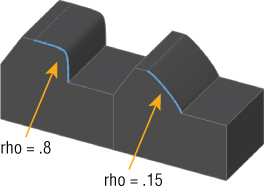
FIGURE 7.26 The effect of parameter rho on Conic rho profile fillets
The Conic radius profile is specified by the main radius value and a conic radius value, which can be any positive number. The Conic radius value is the radius of the conic section curve at the shoulder, which in this case means the middle of the curve. This works in a way similar to the rho value, and the range of effects is similar to what you see in Figure 7.26.
Curvature Continuous profile is available on edge-selected fillets. This is new. Previously, curvature continuity was available only on face fillets, as discussed next. Curvature Continuity (c2) is a spline-based profile that matches the curvature of the faces on either side of the selected edge. This edge-selected c2 fillet is a big convenience over needing to select faces. Any old c2 face fillets you have should still work, but going forward in most cases, the edge-selected fillets will be easier to create.
USING CONTINUOUS CURVATURE FACE FILLETS
Curvature continuity refers to the quality of a transition between two curves or faces, where the curvature is the same or continuous at and around the transition. The best way to convey this concept is with simple 2D sketch elements. When a line transitions to an arc, you have noncontinuous curvature. The line has no curvature, and there is an abrupt change because the arc has a specific radius.
To make the transition from  to
to  smoothly, you would need to use a variable-radius arc if such a thing existed. There are several types of sketch geometry that have variable curvature, such as ellipses, parabolas, and splines. Ellipses and parabolas follow specific mathematical formulas to create the shape, but the spline is a general curve that can take on any shape you want, and you can control its curvature to change smoothly or continuously. Splines, by their very definition, have continuous curvature within the spline, although you cannot control the specific curvature or radius values directly.
All this means that continuous curvature fillets use a spline-based profile for the fillet, rather than circular or elliptical. Figure 7.27 illustrates the difference between continuous curvature and constant curvature. The spikes on top of the curves represent the curvature ( , so the smaller the radius, the taller the spike). These spikes are called a curvature comb.
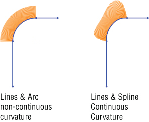
FIGURE 7.27 Using curvature combs to evaluate transitions
Some of these fillet profile options may seem esoteric to you, but there are people who are glad to have these options, and the options are available in some other CAD programs.
Creating Variable-Radius Fillets
Variable-radius fillets are another powerful weapon in the fight against boring designs; they also double as a useful tool to solve certain filleting problems that arise.
APPLYING THE VALUES
When you first select an edge for the variable-radius fillet, the endpoints are identified by callout flags with the value unassigned. A preview does not display until at least one of the points has a radius value in the box. You can also apply radius values in the PropertyManager, but they are easier to keep track of using the callouts. Figure 7.28 shows a variable-radius fillet after the edge selection, after one value has been applied, and after three values have been applied. To apply a radius value that is not at the endpoint of an edge, you can select one of the three colored dots along the selected edge. The preview should show you how the fillet will look in wireframe display.
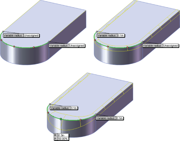
FIGURE 7.28 Assigning values to a variable-radius fillet
By default, the variable-radius fillet puts five points on an edge, one at each endpoint, one at the midpoint, and one each halfway between the ends and middle. If you want to create an additional control point, there are three ways to do it:
- Ctrl+drag an existing point.
- Select the callout of an existing point and change the P (percentage) value.
- Change the Number Of Instances value in the Variable Radius Parameters panel of the PropertyManager.
If you have selected several edges, and several unassigned values are on the screen, you can use the Set Unassigned option in the PropertyManager to set them all to the same value. The Set All option sets all radius values to the same number, including any values that you may have changed to be different from the rest. Figure 7.29 shows the Variable Radius Parameters panel.
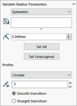
FIGURE 7.29 The Variable Radius Parameters panel of the Fillet PropertyManager
You can set an end of a variable-radius fillet to a value of zero, but you need to be careful because it is likely to cause downstream problems with other fillets, shells, offsets, and even machining operations. You cannot assign a zero radius in the middle of an edge, only at the end. If you need to end a fillet at a particular location, you can use a split line to split the edge and apply a zero radius at that point. (Chapter 8, “Selecting Secondary Features,” covers split lines.) Figure 7.30 shows a part with two zero-radius values.
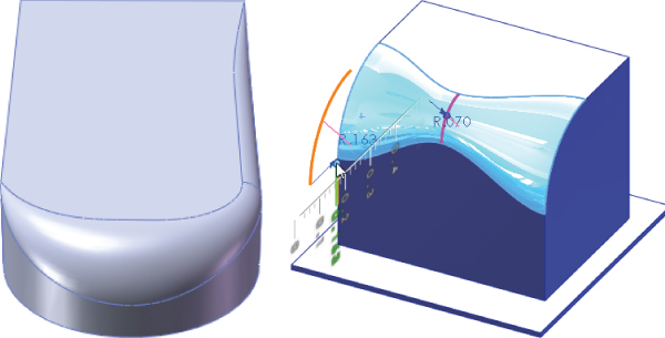
FIGURE 7.30 Zero-radius values in the variable-radius fillet
The image on the right shows Instant3D being used to edit a variable-radius fillet. Select the face of the fillet with Instant3D turned on, and blue dots appear wherever radius values are assigned. You can move these dots to dynamically edit the corresponding value of the variable radius.
USING STRAIGHT VS. SMOOTH TRANSITIONS
Variable-radius fillets have an option for either a straight transition or a smooth transition. This works like the two-profile lofts that were mentioned earlier in this chapter. The names may be somewhat misleading because both transitions are smooth. The straight transition goes in a straight line, from one size to the next, and the smooth transition takes a swooping S-shaped path between the sizes. The difference between these two transitions is demonstrated in Figure 7.31.
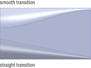
FIGURE 7.31 Straight versus smooth transitions of a variable-radius fillet
RECOGNIZING OTHER USES FOR VARIABLE-RADIUS FILLETS
Variable-radius fillets use a different method to create the fillet geometry than the default constant-radius fillet. Sometimes, using a variable-radius fillet can make a difference where a constant-radius fillet does not work. This is sometimes true even when the variable-radius fillet uses constant-radius values. It is just another tool in the toolbox.
Using Face Fillets
Face fillets may be the most flexible type of fillet because of the range of what they can do. Face fillets start simply as an alternative selection technique for a constant-radius fillet and extend to the extremely flexible double hold-line face fillet, which is more of a blend than a fillet.
Under normal circumstances, the default fillet type uses the selection of an edge to create the fillet. An edge is used because it represents the intersection between two faces. However, sometimes there can be a problem with the edge not being clean, being broken into smaller pieces, or any number of other reasons causing a constant-radius fillet using an edge selection to fail. In cases like this, SolidWorks displays the error message, “Failed to create fillet. Please check the input geometry and radius values or try using the ‘Face Fillet' option.”
Users almost universally ignore these messages. In the situation shown in Figure 7.32, the Face Fillet option suggested in the error message is exactly the one you should use. Here the face fillet covers over all the junk on the edge that prevents the fillet from executing.
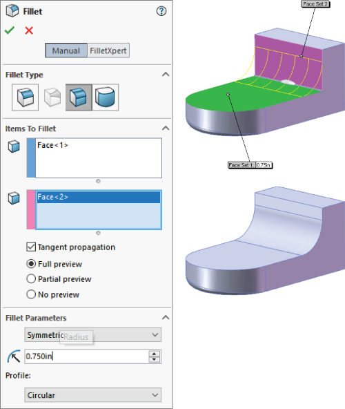
FIGURE 7.32 A face fillet covering a bad corner
Face fillets are sometimes amazing at covering over a mess of geometry that you might think you could never fillet. The main limitation on fillets of this type is that the fillet must be big enough to bridge the gap. That's right, I said big enough. Face fillets can fail if they are either too small or too large. Figure 7.33 shows a complex fillet situation that is completely covered by a face fillet.
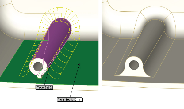
FIGURE 7.33 A face fillet covering geometry
USING FACE FILLETS WITH THE HELP POINT
The Help Point in the Face Fillet PropertyManager is a fairly obscure option. However, it is useful in cases where the selection of two faces does not uniquely identify an edge to fillet. For example, Figure 7.34 shows a situation where the selection of two faces could result in either one edge or the other being filleted (normally, I would hope that both edges would be filleted). The fillet will default to one edge or the other, but you can force it to a definite edge using the Help Point.

FIGURE 7.34 Using a Help Point with a face fillet
In some cases, the Help Point is ignored altogether. For example, if you have a simple box, and select both ends of the box as Selection Set 1, and the top of the box as Selection Set 2, then the fillet could go to either end. Consequently, assigning a Help Point will not do anything, because multiple faces have been selected. The determining factor is which of the multiple faces is selected first. If this were a more commonly used feature, the interface for it might be made a little less cryptic; but because this feature is rarely, if ever, used, it just becomes a quirky piece of trivia.
APPLYING A SINGLE HOLD-LINE FILLET
A single hold-line fillet is a form of variable-radius fillet. Rather than the radius being driven by specific numerical values, it is driven by a hold line, or edge, on the model. The hold line can be an existing edge, forcing the fillet right up to the edge of the part, or it can be created by a split line, which enables you to drive the fillet however you like. Figure 7.35 shows these two options, before and after the fillets. Notice that these fillets are still arc-based fillets; if you were to take a cross section perpendicular to the edge between filleted faces, it would be an arc cross section with a distinct radius. However, in the other direction, hold-line fillets do not necessarily have a constant radius, although they may if the hold line is parallel to the edge between faces.

FIGURE 7.35 Single hold-line fillets
You can select the hold line in the Fillet Options panel of the Face Fillet PropertyManager. The top panel, Fillet Type, is available only when the feature is first created. When you edit it after it has been created, the Fillet Type panel does not appear. As a result, you cannot change from one top-level type of fillet to another after it has been initially created.
USING A DOUBLE HOLD-LINE FILLET
Sometimes, a single hold line does not meet your needs. The single hold line controls only one side of the fillet, and in order to control both sides of the fillet, you must use a double hold-line fillet. SolidWorks software does not specifically differentiate between the single and double hold-line fillets, but they are radically different in how they create the geometry. When both sides of the fillet are controlled, it is not possible to span between the hold lines with an arc that is tangent to both sides unless you were careful about setting up the hold lines so that they are equidistant from the edge where the faces intersect. This means that the double hold-line fillet must use a spline to span between hold lines, as shown in Figure 7.36.
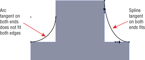
FIGURE 7.36 A double hold line uses a spline cross section, not an arc.
To get this feature to work, you need to use the Curvature Continuous option in the Fillet Options panel. Remember that this option creates a spline-based fillet rather than an arc-based fillet, which is exactly what you need for a double hold-line fillet. This makes the double hold-line fillet more of a blend than a true fillet. This requirement is not obvious to most users and may not even be documented in the SolidWorks Help, nor is it exactly intuitive. To get the double hold-line fillet to work, you must use the Curvature Continuous option. Figure 7.37 shows examples of the double hold-line fillet.
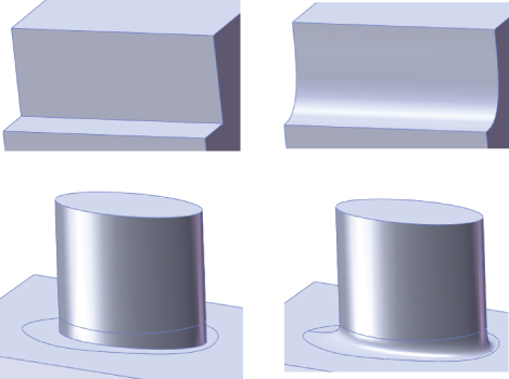
FIGURE 7.37 Examples of the double hold-line fillet
USING A CONSTANT-WIDTH FILLET
The Constant Width option of the Face Fillet PropertyManager drives a fillet by its width rather than by its radius. This is most helpful on parts where the angle of the faces between which you are filleting is changing dramatically. Figure 7.38 illustrates two situations where this is particularly useful. The setting for constant width is found in the Options panel of the Face Fillet PropertyManager. The part shown in the images can be found in the download material as Chapter 7 Constant Width.sldprt.

FIGURE 7.38 The constant-width fillet
Applying a Full Round Fillet
To create a full round fillet, you must select three sets of faces. Usually, one face in each set is sufficient. The fillet is tangent to all three sets of faces, but the middle set is on the end and that face is completely eliminated. Figure 7.39 shows several applications of the full round fillet. Notice that it is not limited to faces of a square block, but it also propagates around tangent entities and can create a variable-radius fillet over irregular lofted geometry.
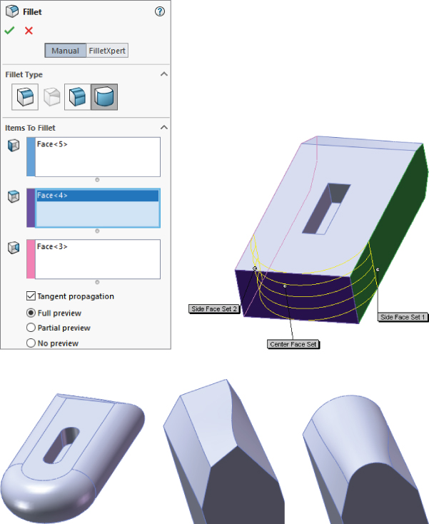
FIGURE 7.39 A full round fillet
Building a Setback Fillet
The setback fillet is the most complex of the fillet options. You can use the Setback option in conjunction with constant-radius, multiple-radius, and variable-radius fillet types. A setback fillet blends several fillets together at a single vertex, starting the blend at some “setback” distance along each filleted edge from the vertex. At least three, and often more, edges come together at the setback vertex. Figure 7.40 shows the PropertyManager interface and what a finished setback fillet looks like. The following steps demonstrate how to use the setback fillet.
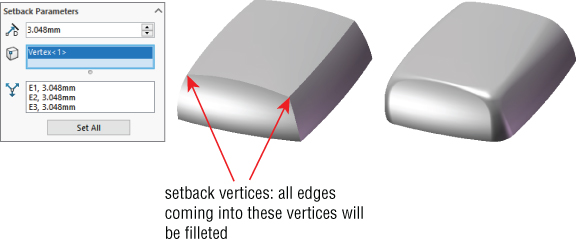
FIGURE 7.40 The Setback Fillet interface and a finished fillet
Setting up a setback fillet can take some time, especially if you are just learning about this feature. You must specify values for fillet radiuses, select edges, and vertices, and specify three setback distances for every vertex. If you are using multiple-radius fillets or variable-radius fillets, this becomes an even larger task. These are the steps:
- Determine the type of fillet to be used:
- Constant-radius fillet
- Multiple-radius fillet
- Variable-radius fillet
- Select the edges to be filleted. Selected edges must all touch one of the setback vertices that will be selected in a later step.
- Assign radius values for the filleted items. Figure 7.41 shows a sample part that illustrates this step.
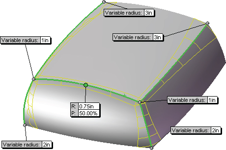
FIGURE 7.41 The setback fillet setup for steps 1 through 3
 Select the setback vertices. In the Setback Parameters panel of the PropertyManager, with the second box from the top highlighted, select the vertices. Although this box looks as if it is only big enough for a single selection, it can accept multiple selections.
- Enter setback values. As shown in Figure 7.42, the setback callout flags have leaders that point from a specific value to a specific edge. Alternatively, you could use the Set All or Set Unassigned options in a similar way to how they are used with the variable-radius fillet interface. The dimensions refer to distances, as shown in the right-most image in Figure 7.42. The setback distance is the distance over which the fillet will blend from the corner to the fillet.
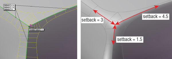
FIGURE 7.42 Entering setback values
- Repeat the process for all selected setback vertices. If you are using a preview, you may notice that the preview goes away when starting a second set of setback values. Don't worry. This is probably not because the feature is going to fail. After you finish typing the values, the preview returns. When you have spent as much time setting up a feature as you will spend on this, seeing the preview disappear can be frustrating; however, persevere and it will return.
Using Chamfers
Chamfers in SolidWorks are not as flashy as fillets. Some similarities exist, such as the propagation to tangent edges, selecting faces to select the loop of edges around the face, and the ability to see full, partial, or no preview of the finished feature. Many of the best-practice ideas you can apply to fillets also apply to chamfers. Figure 7.43 shows the PropertyManager for chamfers.
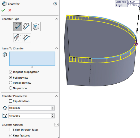
FIGURE 7.43 Working with Chamfer features
You can specify a chamfer using either an angle and a distance or two distance values. For most common situations, these methods are adequate. The situation becomes less definite if you are creating a chamfer between faces that are not at right angles to one another or may not even be planar. These situations require some experimentation to find the correct geometry.
Creating Asymmetrical Chamfers
When you create chamfers at angles other than 45 degrees, you can use the Flip Direction option to control the feature. It is important to note the difference between having direct control (angle the chamfer from this face) and indirect control (angle the chamfer from the other face). Indirect control is essentially trial and error. If you don't like what you are given automatically, you can try the other option.
The Flip Direction option flips the direction of all the chamfers being created by a particular feature. This is obviously important only when you have chamfers made at an angle that is not 45 degrees, or unequal distances in the case of a distance-distance chamfer. So in some situations, where the default directions of more than a single edge are going in opposite directions, your only recourse is to create multiple Chamfer features and control them independently.
One of the most interesting functions of the Chamfer tool is the vertex chamfer, shown in Figure 7.44. You can chamfer a corner with equal distances or distances along each edge. This feature can be used only at corners where three edges come together—standard block corners.
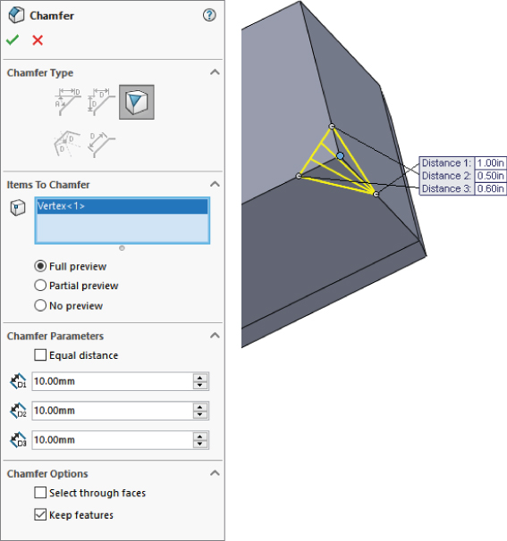
FIGURE 7.44 Applying a corner chamfer
Switching Between Fillet and Chamfer Features
Switching features from fillets to chamfers is now possible, although it has a lot of limitations. You can still start the two features from different icons in the interface, but you can only switch a feature started as a fillet to a chamfer; you cannot change a feature started as a chamfer into a fillet. You can, however, change a fillet to a chamfer back to a fillet.
You may notice that you can't make the change from fillet to chamfer until the Fillet feature has been finished and then edited. So you have to create a fillet, click the green checkmark icon to finish the feature, then right-click and edit the feature, and only then will you be presented with the Chamfer icon at the top of the PropertyManager as shown in Figure 7.45.
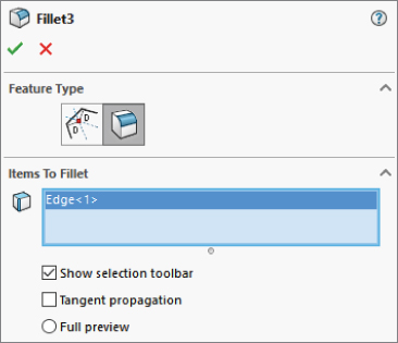
FIGURE 7.45 Changing from a fillet to a chamfer
This may seem odd, because you still can't switch from a constant-size fillet to a variable-size fillet, but you can change from a constant-size fillet to a chamfer. You also cannot change from a variable size fillet to a chamfer. Another change is the terminology from “constant radius” to “constant size,” probably because the fillet profile itself can have multiple radii.
Fillets changed to chamfers retain the automatically assigned Fillet name, but they get a Chamfer icon. You may surmise from this that SolidWorks is preparing to merge Fillet and Chamfer into a new feature called Edge Break, but this is just conjecture and may be incorrect. Because of the unpredictable nature of this change, it will be better for you if you just continue working with separate Fillet and Chamfer features as you have been and try to ignore what appear to be incomplete changes to the Fillet and Chamfer tools.
Tutorial: Bracket Casting
When you follow this tutorial, you are encouraged to follow the directions the first time to make sure that you understand the concepts involved, and then to go through it again, this time deviating from the instructions to see if you can expand your understanding by experimentation. To try bracket casting, follow these steps:
- Open a new part using an inch-based template.
- On the Right plane, draw a circle centered at the origin with a diameter of 1.50 inches, and draw a second circle placed 4.000 inches vertically from the first, with a diameter of 2.250 inches.
- Exit the sketch, and make sure Instant 3D is selected. The Instant 3D icon is on the Features toolbar and looks like a ruler with an arrow. Click the sketch in the graphics window and pull the Instant 3D arrow to create a solid. Edit the feature (right-click or left-click the feature either in the graphics window or in the FeatureManager, and click the Edit Feature icon, which is the yellow and green block with a hand pointing to it). Now enter numbers by hand so you extrude the sketch 1.000 inch using a From condition of Offset by 1.000 inch, such that the offset and the extrude depth are in the same direction. Rename this feature Bosses in the FeatureManager. Figure 7.46 shows the results of these steps.
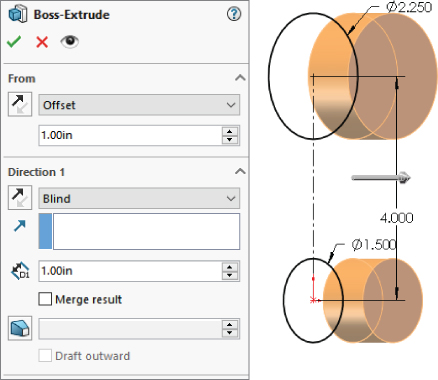
FIGURE 7.46 The results of steps 1 to 3
- On the Top plane in the Top view, open a new sketch and draw a horizontal construction line across the cylinder, from the midpoint of one side to the midpoint of the other side. To pick up the automatic relations for the midpoints more easily, I recommend that you orient the view, normal to the sketch, or use the Top view. It does not matter if you make the relations to the top or bottom cylinder, because the midpoints of the sides are in the same place when they are projected into the sketch plane.
- Draw an ellipse (Tools ➢ Sketch Tools ➢ Ellipse) that is centered at the midpoint of the construction line and that measures 0.700 inches horizontally and 1.375 inches vertically. Remember that horizontal is along the short sketch origin arrow and vertical is along the long sketch origin arrow. You may want to assign a relation between the center of the ellipse and one of the control points to prevent the ellipse from rotating and fully define the sketch. Exit the sketch when you are satisfied with the result.
- Show the sketch for the Bosses feature. Click the plus icon next to the Bosses extrude to show the sketch, and then right-click the sketch and select Show.
- Create a plane parallel to the Top plane at the center of the larger circle. You can access the Plane Creation interface by choosing Insert ➢ Reference Geometry ➢ Plane. If you preselect the Top plane from the flyout FeatureManager and the center of the larger sketch circle from the graphics window, the interface automatically creates the correct plane. Click OK to create the plane. Rename this plane Top Boss Plane.
- Draw a second ellipse on the Top Boss Plane. Do not draw a construction line as you did for the first ellipse; instead, just make the centerpoint of the second ellipse directly on top of the first ellipse's centerpoint. Use the Top view again. The dimensions should be 1.000 inch horizontal by 1.750 inches vertical. Figure 7.47 shows the results up to this point.
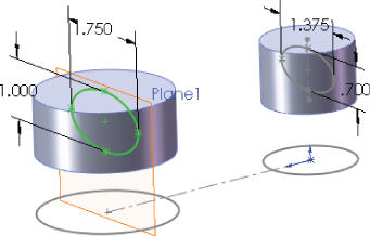
FIGURE 7.47 The results up to step 8
- Use the Loft feature to loft between the two ellipses. Be sure to select the ellipses in approximately the same location so they do not twist. If the loft preview accidentally twists, use the connectors (light-blue square dots on the sketches that are connected by a straight line) to straighten out the loft.
- Right-click all sketches that are displaying and select Hide. Do the same for the Top Boss Plane. This cleans up the display to prevent it from becoming confusing. However, if you prefer to see the sketches, then you can leave them displayed.
- Open a sketch on the Right plane. Sketch an ellipse such that the center is oriented 1.750 inches vertically from the origin, and the ellipse measures 0.750 inches horizontally and 1.500 inches vertically.
- Extrude this ellipse using the Up To Next end condition. If Up To Next does not appear in the list, change the direction of the extrude and try it again.
- Show the sketch of the Bosses feature by expanding the feature (click the “+” next to it), right-clicking or left-clicking the Sketch icon, and clicking the Hide/Show icon (eyeglasses). Next, open a sketch on the Right plane. Sketch two circles that are concentric with the original circles, with the dimensions of .875 inches and 1.250 inches. Exit the sketch.
- Use Instant 3D to create an extruded cut that goes through the large circular bosses. This feature will look like a boss extrusion at first, so when you have finished dragging its depth, a small toolbar with two icons appears. One of the icons enables you to add draft; the other enables you to turn the boss into a cut. Figure 7.48 shows the state of the model up to this step.

FIGURE 7.48 The results up to step 14
- Start a Fillet feature and select the face of the Loft feature. Assign a radius of 0.200 inches.
- Create a Mirror feature, using the Right plane as the mirror plane. In the Mirror PropertyManager, expand the Bodies To Mirror panel, and select anywhere on the part. Make sure that the Merge Solids option is selected. Click OK to accept the mirror.
- Orient the view to the Front view, and then turn the view on its side (hold down Alt and press the left-arrow key or right-arrow key six times).
- Open a new sketch on the Front plane. From the Heads Up View menu, make sure that Hide All Types is not selected and show Temporary Axes. Draw and dimension a horizontal construction line, as shown in Figure 7.49.
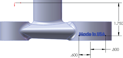
FIGURE 7.49 The results up to step 20
- With the construction line selected, start the Sketch Text command (Tools ➢ Sketch Entities ➢ Text). Make sure the line appears in the Curves selection box.
- Click in the text box, and type Made in USA (or your name or company name). Select the text and click the Bold button. Deselect the Use Document Font option, change the font to use units, and set the height to 0.175 inches.
- Click OK to exit the Sketch Text PropertyManager, and click OK again to exit the sketch. You can turn off the Temporary Axis display.
- Choose Insert ➢ Features ➢ Wrap. You should be prompted to select a plane or a sketch. Use the flyout FeatureManager to select the sketch that you just created with the sketch text in it. Next, select the cylindrical face of the boss to see a preview of the text wrapped onto the face. If the text appears backward, select the Reverse Direction option in the Wrap PropertyManager.
- Select the Emboss option and assign a thickness of 0.025 inches. Click in the Pull Direction selection box and select the Front plane. Click OK to accept the feature.
- Save the part and close it. If you would like to examine the reference part, you can find it in the download materials under the filename
Chapter 7 Tutorial Bracket Casting.sldprt. The finished part is shown in Figure 7.50.
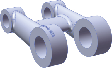
FIGURE 7.50 The finished part
The Bottom Line
SolidWorks has a wide selection of feature types to choose from, ranging from simple extrudes and revolves to more complex lofts and sweeps. Some features have so many options that it may be difficult to take them all in at once. You should browse through the models from the downloads for this chapter and use the Rollback bar (described in detail in Chapter 2, “Navigating the SolidWorks Interface”) to examine how the parts were built. Then you can try to create a few on your own. The best way to learn these features is to use them on practice parts and through experimentation. Curiosity is your greatest teacher.
- Master It Copy the part (remodel it from scratch) called
LowerLinkBibleBike ch7.sldprtfrom the download material. Use the Measure tool under Tools ➢ Evaluate ➢ Measure.
Depending on the type of work you do, Fillet features can be an important part of your job. Work through this exercise to get some practice with fillets.
- Master It Open the part
Chapter 7 fillet example.sldprtfrom the download materials for this chapter. Add fillets to all edges except the outer edges on the Top plane. Remove existing fillets where necessary.
Whether you create a lot of complex shapes or do machine design at your job, sweeps can be important features to master. Open the part Chapter 7 Curves.sldprt and examine how each feature was made. Use the Rollback bar, expand all features, and use the Flatten Tree option (RMB on name of part in FeatureManager, or use Ctrl+T) to try to understand as much as you can about how it was made.
- Master It The curves are the tricky part to this one. You have a 3D sketch, a helix, a projected curve (one sketch projected onto another), and a composite curve (two curves added together end to end). Re-create
Chapter 7 Curves.sldprtusing your own dimensions.