Chapter 10
Using Equations
Parametric sketch relations are not the only way to drive dimensions with intelligence. You can also use equations and variables. Equations help you create simple or complex mathematical relationships between dimensions. Global variables can be used in equations just as other dimension names can.
Understanding Equations
 You can gain access to the Equations dialog box by using the Tools toolbar or by choosing Tools ➢ Equations from the menu. Equations are stored in a folder at the top of the FeatureManager. Figure 10.1 shows the Equations interface.

FIGURE 10.1 The Equations interface
Using the Equations interface, you can suppress individual equations temporarily by deselecting the Active check box to the left of the equation. Equations can also be deactivated by a design table. I discuss design tables in more detail in Chapter 11, “Working with Part Configurations,” where I also discuss configurations.
The Equations interface offers four ways to view the equations:
- Equation View Lists the global variables, features suppressed by equation, and all equations in the part or assembly.
- Sketch Equation View Lists all equations and variables used in sketches.
- Dimension View Lists all global variables, features suppressed by equation, and dimensions in the part or assembly that can be used in equations.
- Ordered View The simplest view. It lists the driven variable, the equation itself, the value of the equation, and any available comments.
Creating Equations
Let's take a look at a part with a variable hole pattern. Equations can be used to space holes along the length of a bar. To prepare for this, we need to name some dimensions that will be used in the equations.
NAMING DIMENSIONS
It is not necessary to name every entity in every SolidWorks document, but you should get in the habit of naming important features, sketches, and even dimensions. Named dimensions become particularly important when you use them in equations, configurations, and design tables. Under most circumstances, you do not use or even see dimension names, but with equations, you do.
Named dimensions make a huge difference when you want to recognize the function of an equation by simply reading it. A most obvious example would be the difference between D3@Sketch6 and Length@WindowExtrusionSketch. The first name means nothing, but the second one is descriptive if you are familiar with the part.
To name a dimension, click the dimension and type the new name in the top of the Modify box—or you can go to the Dimension PropertyManager and, in the Primary Value panel shown in Figure 10.2, type the new name for the dimension in the Name text box. You cannot use the symbol @ in dimension names, because it is used as a delimiter between the name of the dimension and the feature or sketch to which it applies. Also, be aware that even though the software appears to allow you to change the name of the sketch or feature in the Dimension PropertyManager, it will not accept this change. You can't change the sketch or feature name from the Dimension PropertyManager.

FIGURE 10.2 Renaming a dimension
Other ways also exist to change dimension names, including using Configuration Table View and the Equation Manager/Dimension view.
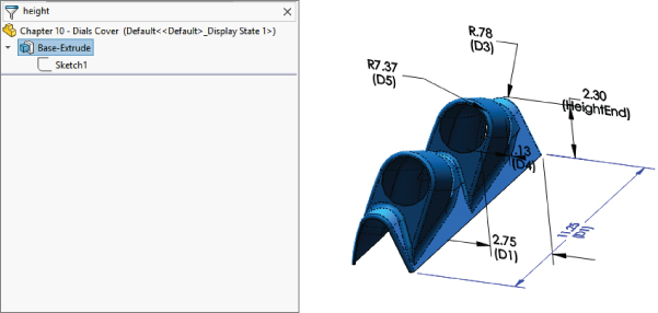
FIGURE 10.3 Using the FeatureManager Filter to filter dimension names
You can use the FeatureManager Filter to find features with specific dimension names. In Figure 10.3, the filter finds Sketch1, which has the HeightEnd dimension. The model view is shown just to illustrate the dimension. The filter did not display the dimension on the model, but clicking a feature found by the filter displays the value.
BUILDING THE EQUATION
When creating an equation in SolidWorks, it is often a good idea to write it out on paper first to make sure that the concept is correct. Examine the part shown in Figure 10.4, where the relevant dimensions have been named and displayed. (The part shown in Figure 10.4 is included with the download material for this chapter. The filename is Chapter 10 Equations.sldprt.) The number of holes—called Instances here—is the driving variable. From that number, the spacing of the holes is calculated over the length of the part. There is also a gap on each end of the pattern of holes. This gap (measured between the center of the last hole and the end of the part) always needs to be half of the spacing between the holes. The sigma symbols (Σ) to the left of the dimensions indicate that an equation is driving it. Dimensions driven by equations cannot be directly edited.

FIGURE 10.4 Variables for the hole pattern
In this case, a more sophisticated equation has not been implemented to account for the diameter of the holes possibly interfering with one another when there are a large number of holes. In other words, because there are two values that need to be calculated (the spacing and the gap), you need to create two equations. Because the gap dimension is always half of the spacing, the spacing needs to be calculated first, as follows:
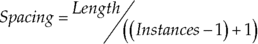
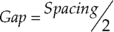
The Instances –1 term stands for the number of spacings. If you have two holes, then there is only one spacing. The +1 term stands for the two half-spacings for the two ends. The second equation is simpler and looks like this:
The order of the equations is important. The SolidWorks Equations interface figures out if there is a necessary order to the equations and puts them in that order. Because the gap is dependent on the spacing, the spacing must be calculated before the gap. SolidWorks also automatically figures out if the equations need to be solved multiple times in order to stabilize. Figure 10.5 shows the resulting set of equations. Notice that the Equations interface this time is being shown in Ordered view, as opposed to Equation view in Figure 10.1.

FIGURE 10.5 Equations for the hole pattern
Before beginning to build the equation, you should first display the dimensions that you need to use to create the equation. You can add dimensions to the equation by clicking them from the graphics window. To do this, right-click the Annotations folder at the top of the FeatureManager and select Show Feature Dimensions. You also should select the Display Annotations (Heads-Up View toolbar ➢ Hide/Show All Types ➢ View Component Annotations) option if it is not already selected as shown in Figure 10.6. When you have done this, all the dimensions that you need to create every feature are displayed. Also, be sure to turn on the Show Dimension Names option; you will find it on the Heads-Up View toolbar.
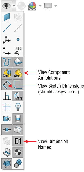
FIGURE 10.6 Showing all the dimensions in a part
To build the equation, go to Tools ➢ Equations. (As an alternative, you can click Equations on the Tools toolbar or right-click the Equations folder in the FeatureManager and select Manage Equations.) Make sure you have the Ordered or Equation view activated (in the upper-left corner, sigma (Σ) is Equation view, dimension is Dimension view, and 123 is Ordered view).
Next, click in the Add Equation box (at the bottom of the list), and then click the dimension you want to drive. SolidWorks adds the name of the dimension and automatically switches focus to the Value/Equation column where you enter the body of the equation. Click the driving dimensions shown in the view as needed, type as needed, or select from lists of functions or properties.
You can also measure right here in the Equations dialog box. Any measurement you make is saved as a reference dimension and entered into the equation as such. When you have a valid equation, SolidWorks fills out the Evaluates To column for you. Notice also that if your equation is valid, a green check appears in the box. If it is not valid, the syntax that makes it invalid is displayed in red, and the check mark is shown in gray.
USING COMMENTS
Notice the comment to the right of the Evaluates To column in Figure 10.5. Comments can be very useful for annotating equations for yourself or others. Two important reasons to annotate are to remember the significance of variables or dimensions and to add special notes about the logic of the equation that may not be obvious.
Using Driven Dimensions
Sometimes it is necessary to use a driven (reference) dimension in an equation. Reference dimensions are displayed in gray. This is particularly true when the best way to calculate a number is to use existing 3D geometry. For example, if you are manufacturing a helical auger in 90-degree sections from flat steel stock, you need to design the auger in 3D but begin to manufacture it in 2D.
What is the shape of the auger when flat? The best way to figure this out (aside from lofted bends, which are discussed in Chapter 34, “Using SolidWorks Sheet Metal Tools”) is to use a little high-school geometry, a construction sketch, and some simple equations.
Figure 10.7 shows a 90-degree section of an auger blade. The outside diameter is 12 inches, and the blade width is 3 inches. (The part shown in Figure 10.7 is included with the download material for this chapter and is in the file named Chapter 10 Auger.sldprt). The overall height is 4 inches. In this case, the auger is represented as a surface because the thickness is ignored. Surface features can be useful in situations like this (used as construction geometry) and are discussed in Chapter 32, “Working with Surfaces.”
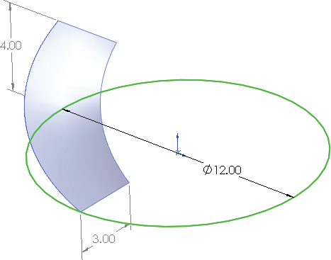
FIGURE 10.7 A representation of the auger
With this information, you can calculate the lengths of the 3D edges using a sketch and a simple equation. In Figure 10.8, the hypotenuses of the triangles represent the helical edges of the inside and outside of the auger. By making the triangles the same height as the auger section, and by making the horizontal side of the triangle the same length as a quarter of the inside or outside diameter by using simple equations, the geometry and sketch relations automatically calculate the flat lengths of the inside and outside edges of the auger 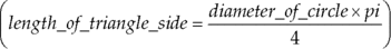 . In this way, the triangle is used to simplify the calculation and give it a visual result.
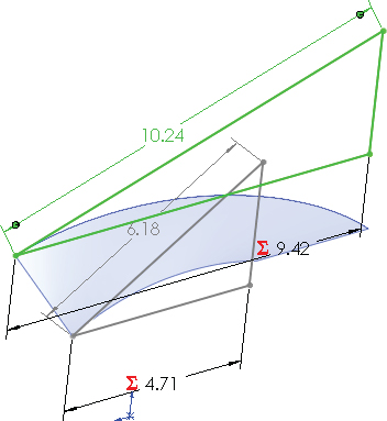
FIGURE 10.8 Triangles calculate the length of the helical edge.
From this point, you can calculate the flat pattern again, using the SolidWorks sketch-solving capabilities as the calculator. Think of the auger as being the cardboard tube inside a roll of paper towels. If you examine one of these tubes closely, you will see that it is simply a straight and flat strip of cardboard that has been wound around a cylinder. What was the flat, straight edge of the original board is wound into a helix. This method simply reverses that process.
This example requires the little-used arc-length dimension to drive the size of the arc. The hypotenuse dimensions are shown by driven dimensions or reference dimensions, which are used to drive the arc-length dimensions, as shown in Figure 10.9. Remember that you can create arc length dimensions by using the Smart Dimension tool to click both endpoints of the arc and then the arc itself.
FIGURE 10.9 Figuring the flat pattern of the auger
The reasoning behind this example may be a little difficult to grasp, but the equations and the sketches are certainly simple.
Using Equation Tricks
SolidWorks equations allow several mathematical operators, such as sine, cosine, tangent, and others. SolidWorks also allows IF statements, conditional operators (=, <, >, < >, =>, <=), and file properties.
USING IF STATEMENTS
In words, this is how an IF statement is used:
- If some relationship is fulfilled, then the
IFfunction returns a value. If the relationship is not fulfilled, then it returns a different value.
A more technical description is
- IF(expression, value if true, value if false)
In practice, you could use it like this:
- IF(x > 5, x-1, x+1)
which reads, “if x is greater than 5, then subtract 1 from x; if not, then add 1 to x.” One of the reasons why this is considered a parlor trick is that this function causes the value of x to oscillate between two numbers (depending on the number that it starts with) with each rebuild. SolidWorks also identifies this as a circular reference because the same value is on both sides of the equation. It may be difficult to imagine an application where this sort of behavior would be desirable, but when you combine it with a macro that simply rebuilds a model a number of times, you can use it to create a certain animation effect. Figure 10.10 shows an equation using the IF function.

FIGURE 10.10 An equation using IF
You can use an IF statement—or any other VBA (Visual Basic for Applications) function—to control the suppression state of features and components. This function is described in detail later in this chapter.
Using Global Variables
A global variable (supersedes pre-2012 link value) is just a name assigned to a dimension, a reference measurement, or an entire equation. Linked values are still extremely powerful tools. The fastest way to link multiple dimensions in bulk is by using a link value.
Global variables are assigned in the Equations dialog box or in the Modify dimension box as simply the variable name equaling an expression or a value. Figure 10.11 shows a list of equations and global variables. When you type a variable name, you do not need to add the quotation marks; they are added automatically. The global variable named “multiplier” uses an expression to calculate its value. The global variable shown in Figure 10.11 called “global variable” is simply assigned a value directly.
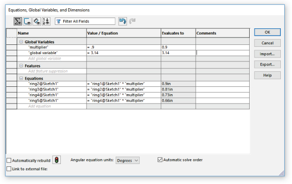
FIGURE 10.11 Equations and global variables
You can use custom and file properties to drive equations. If you right-click your Equations folder and select Show File Properties, you will see that the default file properties already exist in the list, as shown in Figure 10.12.
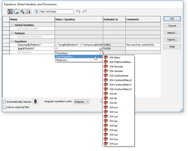
FIGURE 10.12 Equations and properties
In the Equation Editor shown in Figure 10.12, you can expand the list of functions and custom properties for easy selection and placement into equations. Any custom properties you add that are of the type “number” are automatically added to this list and can be used in equations.
Note that you can assign both a custom property and a global variable with the same name. The global variable takes precedence over the custom property when evaluating an equation.
Global variables are configurable. Chapter 11, “Working with Part Configurations,” covers this feature in more detail, but the syntax for using a design table to drive a global variable is as follows:
$VALUE@global_variable_name@equationsUsing the Modify Box
The Modify dimension box can accept equations. You can also use it to create on-the-fly global variables.
To start an equation in the Modify box, first replace the numeric value with an equal sign (=) in the value box. When you do this, you will see a dropdown for functions and file properties, as shown in Figure 10.13. You can also change the name of the dimension right there. To add other dimensions to the equation, just click them.

FIGURE 10.13 Starting an equation in the Modify box
If you key in a numerical value, SolidWorks offers a drop-down list of possible units, properties, or operators. If you don't select anything, then the document units setting is used.
Additionally, you can use dimension-entry boxes in PropertyManager windows in the same way, as shown in Figure 10.14.

FIGURE 10.14 Using the PropertyManager dimension-entry box to write an equation
Using Expressions
Expressions can also be entered directly into Dimension dialog boxes in the Modify dialog box and PropertyManager value boxes. The expressions must be composed of numbers and mathematical operators. An expression such as
- 2.375+(4.8/3)-1.1
is perfectly acceptable, as is
- 1+1/2
or
- 1 1/2
In the second case in this example, the plus symbol is understood.
Other types of operations are also available, such as ones for changing units in a dimension box. For example, if you are editing a part in inches and enter 40mm, then SolidWorks performs the conversion for you. You can even mix units in a single expression such as 4.875+3.5mm, where the inch part is assumed as the document units.
Unlike equations, SolidWorks does not remember the expression itself, only the final value. The difference between an expression and an equation is the presence of dimension or variable names. Expressions can be entered into any place where you enter dimensions for SolidWorks features.
Controlling Suppression States of Features
You can use the IF statement described earlier in this chapter to control suppression states of features and components. An example of the syntax is
- <feature name> = if(expression, value if true, value if false)
Figure 10.15 shows this type of equation in use. In this case, the features area is in the middle of the chart in Equations view. To get the feature into the cell, make sure the cell is selected and click the feature in the FeatureManager or graphics window. Anything in quotes can be selected, so you don't have to worry about spelling or syntax. The IF statement reads in English, “If the spacing is greater than 0.5, then do not suppress. If not, then do suppress.” There's a little double-negative thing going on here, but it is the suppression state, not the existence of the feature itself that you are controlling.
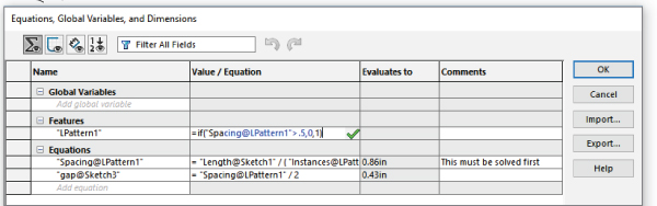
FIGURE 10.15 Using IF to control suppression states
You can also use this equation in assemblies to control suppression states of components (parts and subassemblies).
Linking to External Equations
You can use externally saved equations to share equations between models. To export an equation, click the Export button on the right side of the Equations dialog box, as shown in Figure 10.15. To link the current model to the externally saved equation, make sure the Link To External File option is checked at the bottom left of the Equation Export dialog box, as shown in Figure 10.16.

FIGURE 10.16 Saving an equation to an external file
The equation is saved to a simple *.txt file. The default name for the external equation text file is equations.txt. You can change the name if you like, but remember that if you use Windows Explorer to change the name or change it with the referencing file closed, SolidWorks will not know that the filename has been changed. At the bottom of the Equations dialog box is a path for a linked equation file. You can link to only one equation file at a time.
To link to an existing equation from a SolidWorks model, use the Import button in the Equations dialog box. Also be aware that only equations and global variables can be shared in this way.
Tutorial: Using Equations
Get some practice with using equations by following these steps:
- Start from the part with the filename
Chapter10 Tutorial Start.sldprtin the download materials, shown in Figure 10.17.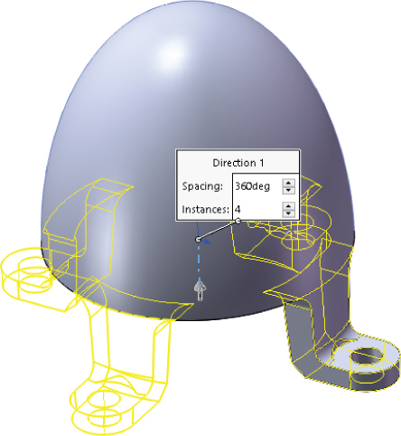
FIGURE 10.17 Starting the Equations tutorial
- Show the dimension names. Use the Heads-Up View toolbar to find this setting.
- Double-click the Circular Pattern feature to display the angle and number of instances of the feet and related features. You may have to move the angle dimension to see the pattern instance number.
- Click the instance number. Change the name of the dimension to # (pound or number sign) in the Dimension PropertyManager. Make sure that the Instant3D option is deselected when you do this.
- Double-click the first feature in the FeatureManager, which is the revolve, and rename the 3.60-inch dimension CapRad, again by selecting it and using the PropertyManager.
- Write an equation that drives the number of legs by CapRad/7.
- Open the Equations dialog box by choosing Tools ➢ Equations.
- Click Add to add an equation.
- Double-click the Circular Pattern, and click the # dimension. Make sure that the name of the dimension is listed in the equation box, and type an equal sign (=).
- Double-click the Revolve feature, and select the CapRad dimension; then type /1.5.
- Add a comment to the equation to identify the driving dimension.
- Click Rebuild, press Ctrl+B or Ctrl+Q to rebuild the model, and observe whether any update takes place.
- Rename the 6.00-inch dimension for the height of the revolved feature to DomeHt.
- Create a second equation that drives the DomeHt dimension at the current ratio of the height to the radius.
- In the Equations dialog box, create a global variable called Ratio = 6/3.6 (1.66667).
- Create the equation. The equation takes the form of DomeHt = (Ratio) × CapRad. You can use the drop-down list under the calculator pad to select the Ratio variable from the list.
- Use a variable to make the radii of Fillet1 and Fillet2 the same.
- Double-click the Revolve feature. Change the CapRad dimension to 5 and rebuild. You should observe three feet. Change it again to 6, and you should see four feet.
- Give the part a new name, including your initials or the date, and save and close it. See Figure 10.18.
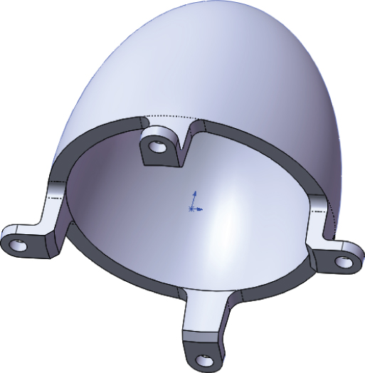
FIGURE 10.18 The finished part
The Bottom Line
SolidWorks equations and related dimension-management tools are powerful. In the last several releases, they have been vastly updated. Even if you're not a huge equation user, the ability to build equations in the Modify and PropertyManager dimension boxes is a great convenience for such a powerful function.
Be careful about crossing SolidWorks native equation functionality with configurations; you may end up with dimensions that are controlled by both tools. Remember that the calculation capability of Excel is far greater than what is found in SolidWorks equations.
- Master It Equations and variables are keys to parametric design. Start simple by creating a rectangle with sides made equal by using the same variable name for vertical and horizontal dimensions.
- Master It After you have created the rectangular sketch with equal sides, make the extrusion depth also equal so that no matter what size it is, the solid will always be a cube.
- Master It One of the most common situations in design is needing to spread out holes. Equations are a great way to do this. Study the part named
Chapter 10 Equations.sldprtand re-create it on your own.