Chapter 24
Automating Drawings: The Basics
SolidWorks drawing templates and formats enable you to automate repetitive tasks through the reuse of data. SolidWorks can insert information about a drawing's creator and the materials to be used, and it can begin similar types of drawings from a consistent starting point. Drawing templates and formats also save settings that you may want to reuse.
Comparing Templates and Formats
Templates are start documents that contain collections of document-specific settings and default views saved in the *.prtdot (part template), *.asmdot (assembly template), and *.drwdot (drawing template) file types. In this chapter, I will cover the *.drwdot file type.
Formats, more formally called sheet formats, are exclusive to drawing documents and contain the sheet size, the drawing borderline geometry, and the text/custom property definitions that go with the text in the drawing border. You can think of a sheet format as an underlay beneath a clear drawing sheet. Formats can also include company logo images.
You can save formats in drawing templates; in fact, this is the method that I use and recommend. Using SolidWorks' default drawing templates, the templates and formats are initially kept separate. You specify the size and the format when creating a new drawing from a blank template. However, when the format is already in the template, the size has already been determined, so the templates end up being saved as specific sizes. Of course, you can change formats later if you need to use a larger drawing sheet, but you cannot change templates.
A SolidWorks drawing template can have multiple sheets, which can be the same or different sizes. You can use a different format for each sheet. For example, if you want a default two-page drawing, you can save it as a template, with different formats for the first and second sheets.
Changing Existing Templates
After you create any kind of document from whatever kind of template, you cannot change the underlying template. However, you can change all the settings, which is the next best equivalent.
SolidWorks offers custom drafting standards, which provide some of the functionality that the ability to swap templates would achieve. You can take a drafting standard such as ISO (International Organization for Standardization) or ANSI (American National Standards Institute), make adjustments to it, and save the standard out to a file that you can distribute to other users. You can change the standard by choosing Tools ➢ Options ➢ Document Properties ➢ Drafting Standard from the menus. You can load and save standards from the same location. More details on what you can actually change within the drafting standard come later in this chapter.
While templates cannot be reloaded, formats can be. You might want to reload a format (drawing border and associated annotations) if you have made changes to the information or line geometry. You can also reload a format to change the sheet size for a drawing.
Maintaining Different Templates or Formats
Different formats must be maintained for different sheet sizes. If you do contract design or detailing work, then you may need to maintain separate formats for different customers. Some people also choose to have different formats for the first sheet of a drawing and a simplified format for the following sheets.
If you put formats on the templates, then you are making separate templates for variously sized drawings. Also, separate templates are frequently created for different units or standards because templates contain document-specific settings. I also keep a blank drawing template with a blank format on it just to do conceptual scribbles or to make an informal, scalable, and printable drawing without the baggage that typically accompanies formal drawings.
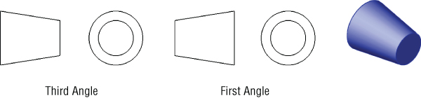
FIGURE 24.1 Third angle versus first angle projection
If you work for a company that does a lot of work for manufacturing in Europe, you may have to deal with this issue more frequently. The setting that controls the projection angle is in the Sheet Properties, which you can access by right-clicking anywhere on the blank drawing sheet and selecting Properties.
Creating Custom Drafting Standards
In my experience, very few real-world companies follow any of the single drafting standards perfectly. Each company seems to have its own interpretation of, or exceptions to, the standards. SolidWorks is coming to grips with this in a practical way. In SolidWorks, you can create your own custom drafting standards, equivalent to the established ISO and ANSI standards. These standards allow you to save all the settings found in Tools ➢ Options ➢ Document Properties to a single standard that you can then transfer to other users.
To make your own custom standard, make changes to any of the items listed indented from Drafting Standard shown in Figure 24.2, and then go back to the Drafting Standard page of the Document Properties tab, rename the Overall Drafting Standard, and save the standard to a file. Once you have made a change to the default settings, the Overall Drafting Standard will be displayed as ANSI-MODIFIED, or as appropriate for your chosen initial standard. You can rename this, and SolidWorks will show which standard it was derived from, to help avoid confusion. I created a new standard, which is shown in Figure 24.2.
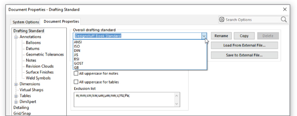
FIGURE 24.2 Creating a new customized drafting standard
The drafting standard file type has the extension of *.sldstd. If someone else has sent you a standard file, you can read it into your drawing using the settings shown on the right of Figure 24.2 and assign it as the active standard; your drawing will assume all the customized properties. If you want to make new drawings with that standard, you need to create a template with that standard and use the template to create the new drawings.
Creating Drawing Formats
It used to be that drawing formats were difficult to create or edit, requiring import and 2D drawing skills. With the addition in 2016 of the Sheet Format tools, this all becomes much easier.
The Sheet Format tab on the drawing adds three new tools: Edit Sheet Format, Title Block Fields, and Automatic Border. These are shown in Figure 24.3.
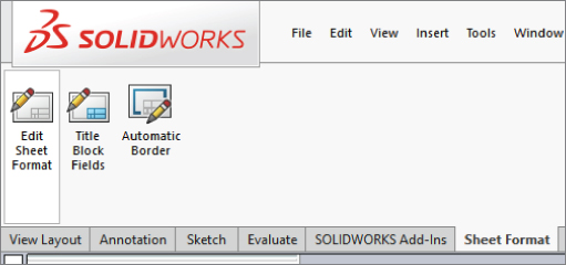
FIGURE 24.3 Sheet Format CommandManager
Edit Sheet Format toggles between editing the sheet (where the drawing views reside) and editing the sheet format (where the title block resides).
Title Block Fields helps you create static and linked annotations in the title block area that can be filled out automatically by custom properties in part and assembly documents. The functions of this tool are described later in this chapter under the heading “Using the Title Block Function.”
The Automatic Border tool helps you place a border with zones to frame the drawing. This multistep tool walks you through deleting the existing border elements; establishing zones, margins, and line styles; and placing the new border, which is an entity that shows up in the FeatureManager for the drawing under the sheet and sheet format. You can edit these by going back to the Sheet Format tools (not by editing the 2D lines).
Customizing an Existing Format
Existing formats created manually or by importing can also be used.
The sample formats installed with SolidWorks include ANSI sizes A through E and ISO sizes A0 through A4. You can probably find enough space on the formats to place a company logo and some standard notes. Choose Tools ➢ Options ➢ File Locations to locate the path for your templates. Remember that you can use network drives for shared libraries.
You cannot open a format directly—it must be on a drawing—so to get a closer look at the format, you must make a new drawing using the format.
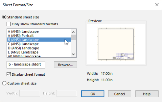
FIGURE 24.4 Selecting a format
EDITING A FORMAT
In the drawing, whether the format has been created using new or old tools, you are either editing the sheet or editing the format. You can think of the sheet as being a piece of transparent Mylar over the top of the drawing border format. In order to get to the format, you have to peel back the Mylar. Drawing views go onto the sheet, so when you edit the format, any drawing views that may be there disappear.
To peel back the sheet and gain access to the format, right-click a blank area of the sheet and select Edit Sheet Format. Alternatively, you can access the sheet format by right-clicking the Sheet tab in the lower-left corner of the SolidWorks window. Be careful of the terms here, which include “Sheet” and “Sheet Format.” The sketch lines of the format will light up like a sketch becoming active, and the “Editing Sheet Format” message will appear at the lower-right corner on the status bar.
The lines in the format border are regular SolidWorks sketch entities, but they display a little differently. Also, sketch relations are sometimes disabled in formats because solving the relations would cause the software to run slowly. Typically, the Trim, Extend, and Stretch functions are the best sketch tools for editing lines.
You can use most common image types to insert a logo or other image data onto your drawing or format by choosing Insert ➢ Picture. Not all compression styles are supported, however. I have had difficulty with compressed TIFF (Tagged Image File Format) images. Be aware of the file size of the image when you put it into the format, because images can be large, and all that extra information will travel around with each drawing that you create from the format. Figure 24.5 shows a bitmap placed in the format.
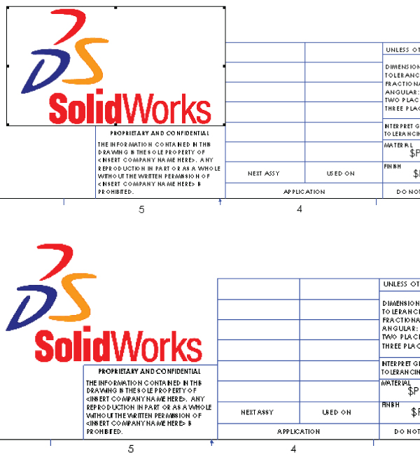
FIGURE 24.5 Placing an image
You can resize the image by dragging the handles in the corners; you can move it by simply dragging it. The image to the right in Figure 24.5 was taken from the Print Preview window. I included it here to show that the outline around the image that displays while you are working in SolidWorks does not print.
MANAGING TEXT
SolidWorks allows you to make a text box of a specific size that causes text to wrap. This is particularly useful in drawings. The upper image in Figure 24.6 shows a new annotation being added. The lower image shows the same text box after the corner has been dragged.
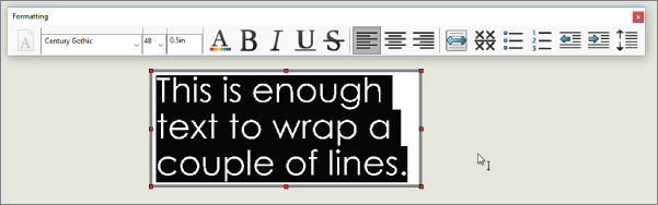
FIGURE 24.6 Adding an annotation and wrapping the text
Using Custom Properties
The most important part of the drawing format is the custom properties. While the rest of the format is just for display, custom properties use automation to fill out the title block using matching custom properties in either the model or the drawing document. Custom properties can pull items such as filenames, descriptions, materials, and other properties from the model associated with the sheet, or they can pull data from the drawing itself, such as the sheet scale, filename, sheet number, and total sheets. If you are seriously looking to automate drawings, you cannot overlook custom properties.
ENTERING CUSTOM PROPERTY DATA
Custom property data is entered at the part or assembly level. This information is then reused in the drawing format and in tables such as BOMs (Bills of Materials) and revision tables, as well as searches using the FeatureManager filter. All PDM (Product Data Management) systems utilize SolidWorks custom properties. You can enter the data several ways, but the two most prominent ways are through the Summary Information dialog box and the Custom Properties tab in the Task pane.
USING THE SUMMARY INFORMATION DIALOG BOX
Figure 24.7 shows the Summary Information dialog box. This functionality has existed in SolidWorks for several releases. You can access this dialog box by choosing File ➢ Properties from the menus. You can select Property Names from a drop-down list or type your own, assign types of data, and enter a specific value for the property. The Value/Text Expression column also has a drop-down list from which you can select several preset variables, such as mass, density, and even link values used in the part.

FIGURE 24.7 The Summary Information dialog box
This is a perfectly functional way to enter data, but the fact that it's somewhat out of the way and hidden in the menus means that it doesn't get used as much as it should. SolidWorks came up with another way of entering data.
USING THE CUSTOM PROPERTIES TAB
The Custom Properties tab of the Task pane enables you to quickly and easily access and assign custom properties within a document. Figure 24.8 shows the process of building your own Custom Properties tab. You can start the Custom Property Tab Builder by either clicking the Create button on the Custom Properties tab or choosing Start ➢ Programs ➢ SolidWorks ➢ SolidWorks Tools ➢ Property Tab Builder from the menus.
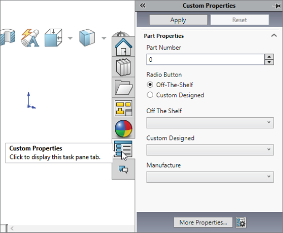
FIGURE 24.8 Using the Custom Properties Builder and Custom Properties tab
The interface enables you to add drop-down lists, toggles, and text entry boxes. This gives you lots of flexibility with custom property data entry and is a very nice addition to the software.
DISPLAYING PROPERTY LINKS
Figure 24.9 shows the existing custom property formatting in the default format being used for this example.
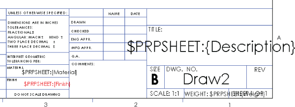
FIGURE 24.9 Custom property formatting in the title block
The syntax $PRP or $PRPSHEET indicates that the property that follows the syntax is to be pulled from either the current document (drawing) or from the model specified in the Sheet Properties, respectively. This is an important distinction to make. Most of the time, you can enter custom properties at the part or assembly level so you can reuse the data by drawing properties, BOM, or even design tables.
Notice that all the notes in the format that are showing raw syntax are pulling data from the model. “Draw2” and the Scale notes are driven by the drawing. When no value exists for the property to display, you have an option of what to show. The top portion of Figure 24.10 shows the settings in the View ➢ Hide/Show menu that control the display of syntax of the custom property links. In general, it is common to deselect the error display and to show the link variables.
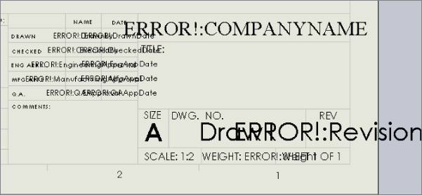
FIGURE 24.10 The link variable's display options and effects
DISPLAYING ERRORS AND LINK VARIABLES
The errors in Figure 24.10 are caused by links to the local document for which there is no corresponding property. For example, the “ERROR!: COMPANYNAME” message is linked to “$PRP: COMPANYNAME,” but the local custom property COMPANYNAME doesn't exist. If it existed but had a null or space value, the error would disappear.
Likewise, with the option to display link variables selected, the syntax that calls model custom properties displays until there's some value for it to pull from. If a part is put onto the drawing, then some of the properties are filled in because properties and values exist to pull from, and the rest of the properties simply disappear to make space. Notice in Figure 24.11 that the Material property has been filled in, but the Finish property has not. This is because either there's no Finish property in the part on the drawing or there's a null value in the Finish property.
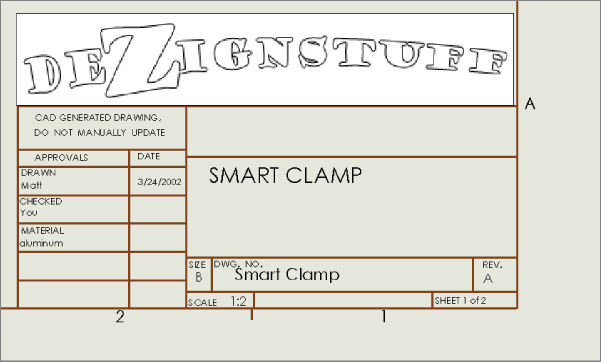
FIGURE 24.11 Custom properties filled in by a part
CREATING LINKED PROPERTIES
Creating annotations that are linked to properties is easy. Begin as if you are creating a note:
 Click the Note toolbar button on the Annotations toolbar, or choose Insert ➢ Annotations ➢ Note.
- Place the note on the drawing. The Formatting toolbar will appear.
 Click the Link To Property button in the Text Format pane of the Note PropertyManager. This will display the Link To Property dialog box, as shown in Figure 24.12, which gives you the option of linking to a custom property in the current (drawing) document or in the model (part or assembly) that's on the drawing.
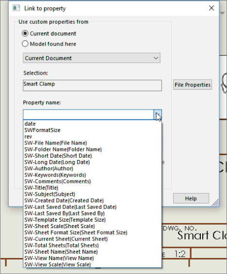
FIGURE 24.12 The Link To Property dialog box
- If the desired custom property is not in the drop-down list, you can type it into the text box or click the File Properties button to edit the properties. If the property is added to the part file or a part file with that property is used on the drawing, this linked annotation will pick it up. This button will not be available for the model if there's no model on the drawing, in which case you must type the name of the property manually.
Using the Title Block Function
The title block enables the person who sets up the sheet format to specify an area that contains notes that are easy to access without editing the format. (Many CAD administrators prefer that the users not have to deal with the details inside the sheet format.) You can even cycle through these notes in a specific order by pressing Enter or Tab. Figure 24.13 shows the resizable black border of the title block, the Title Block PropertyManager, and where the title block sits in the drawing FeatureManager.
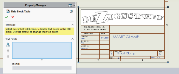
FIGURE 24.13 Using the Title Block Table
You can access the title block to edit or define it by right-clicking in the sheet format (while editing the sheet format, not the sheet) and selecting Title Block Fields, and then either edit existing notes or select new notes as the situation requires.
The title block is a resizable rectangular box. It can be any size you like, but it must remain rectangular, and you can create only one title block area per sheet format. The area bounded by the title block box is used to zoom the display to make it easier to fill in the text boxes. If you want to include areas in different corners of the drawing in the title block area, you need to make the title block box as big as the entire sheet, and the user must manually zoom to each corner.
Select each Note item to add it to the list in the PropertyManager selection box. Use the arrows to the left of the box to assign the order in which the user cycles through the boxes. You can even add a tooltip for each note. The idea is that the user clicks in a box within the title block area, fills it in, and then presses Enter or Tab to get to the next box. The order loops if the user doesn't start on the first box listed in the PropertyManager.
You cannot add notes that are already linked to properties to the title block, because they will be filled out automatically. The purpose of the title block is really to highlight and speed up manual entry.
To use an existing title block, just double-click in the title block area (designated by the resizable rectangle) from the sheet (not the sheet format), and SolidWorks will highlight the fields.
Creating a Format from an Imported DWG/DXF file
If you want to create your format from an imported DWG or DXF file, choose File ➢ Open to locate the file that you want to import and then click to open it. The DXF/DWG Import screen will appear, as shown in Figure 24.14.
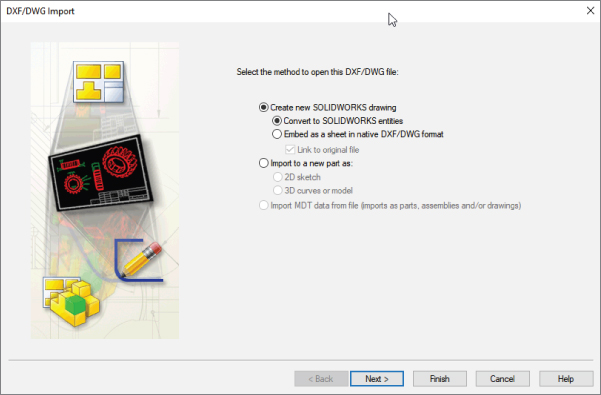
FIGURE 24.14 The DXF/DWG Import screen
If you are interested in following along, you can find the sample files used for this example in the download data for Chapter 24. You'll find five *.dwg format files. You can use any of them to create a format, but I suggest using either the A or B size. To make a drawing format, you can select the Create New SolidWorks drawing and Convert To SolidWorks Entities options. Although one of the other options contains the word format, it isn't being used in the same sense, so don't be misled. When this selection is complete, click Next. Figure 24.15 shows the next screen.
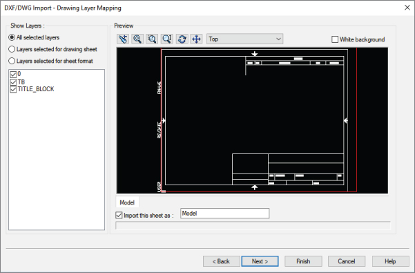
FIGURE 24.15 The Drawing Layer Mapping screen
Select the Layers Selected For Sheet Format option. Select the TB layer, leaving the other layers unselected. Every imported file will be different in this respect, because layers used by title blocks vary widely. Click Next when you have made these selections. Figure 24.16 shows the Document Settings screen.
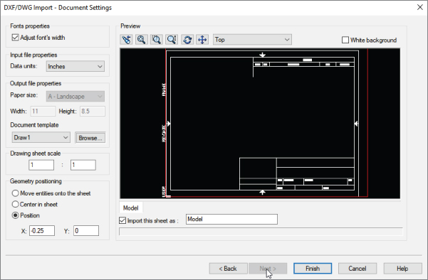
FIGURE 24.16 The Document Settings screen
The important features in the Document Settings screen are the Document Template selection and the Geometry Positioning options.
Document Template selection is important only if you plan to save the format with a template. Be sure to select a template that doesn't already have a format saved in it. In the Geometry Positioning section, if you can get the software to center the title block for you, definitely take advantage of this functionality and use the Center In Sheet option. After you're happy with these settings, click Finish. The resulting format is shown in Figure 24.17.
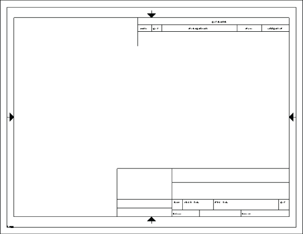
FIGURE 24.17 The finished imported format
From here, you can add the links to custom properties as described earlier, as well as logo images, favorites, and blocks. You can now save the format as described in the next section.
Saving the Format
You can save drawing formats in two ways: with the template or separately from the template. You cannot edit formats separately from a template, but they do have their own file type: *.slddrt.
Saving templates is covered in the next section. To save a format, choose File ➢ Save Sheet Format. You can do this with or without the format being active. Save the format into a location with other formats and give it a descriptive but unique name. If you haven't yet done so, this is a good opportunity to create a separate folder, outside of your SolidWorks installation folder, that contains your most frequently used files. Remember also to tell SolidWorks where this library location is by choosing Tools ➢ Options ➢ System Options ➢ File Locations ➢ Sheet Formats.
Even if you have saved a format with a template, it's a good idea to also save the format on its own. This is because you might want to use that format on an existing drawing that has a different format on it or use it on a second sheet.
Using Second Sheet Formats
When you have multi-sheet drawings, it is often important to have a simplified or specialized format for the second sheet. Figure 24.18 shows sample page-one and page-two formats side by side.
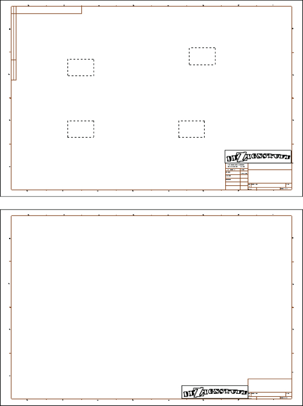
FIGURE 24.18 First and second sheet formats
ADDING NEW SHEETS
 You can add sheets to a drawing by clicking the Add Sheets icon to the right of the Sheet tabs at the bottom of the SolidWorks window or through the RMB menu of the Sheet tab at the lower-left corner of the drawing window. You can also add a sheet by RMB on the sheet or sheet format in the FeatureManager. If you right-click the first Sheet tab, the sheet that is added gets the format that is used on the first sheet. If you right-click the second Sheet tab, the added sheet gets the second sheet format.
RELOADING FORMATS
If a format has been changed, and you want to update a drawing to the new format, this option is available in the Sheet Properties, as shown in Figure 24.19. Access Sheet Properties through the RMB on the sheet in the FeatureManager. The Reload button will update any changes in the separate format file.
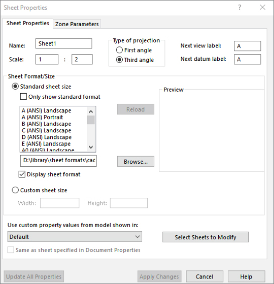
FIGURE 24.19 Updating a format through the Sheet Properties
Creating Drawing Templates
Document-specific settings are important parts of the template, and it's probably best to get one drawing size completely set up the way you want it and then create the other sizes from this drawing. This helps to ensure that the settings—such as Bent Leader Length, Font, and Line Weight—are the same for all the templates. Uniform settings on drawings give them a consistent look and make them easier to read. Drafting standards are controlled by drawing templates.
Using Predefined Views in Drawing Templates
 When I use drawing templates, one of my favorite techniques to get to a multi-view drawing quickly is to put one predefined view on the template along with appropriate views projected from the predefined view. A predefined view establishes an orientation and location on the drawing sheet. You can add multiple predefined views and align them with one another on the drawing sheet so a drawing is automatically populated by the model, but this isn't recommended, because if you decide to change the orientation of the drawing, you must change each predefined view independently. If you set up a single predefined view and make the rest of the views with projected views, changing the orientation of the predefined view will cause all the projected views to update associatively. You cannot directly change the orientation of a projected view. Predefined views and views projected from predefined views appear blank until they are populated with model geometry. The predefined part of a predefined view is the orientation and placement of the view.
Figure 24.20 shows a template using predefined and projected views. You can access predefined views on the Drawings toolbar; although it isn't there by default, you can place it on the toolbar by choosing Tools ➢ Customize ➢ Commands and using the interface. You can also access predefined views by choosing Insert ➢ Drawing Views ➢ Predefined. Projected views can also be accessed from the Drawings toolbar.
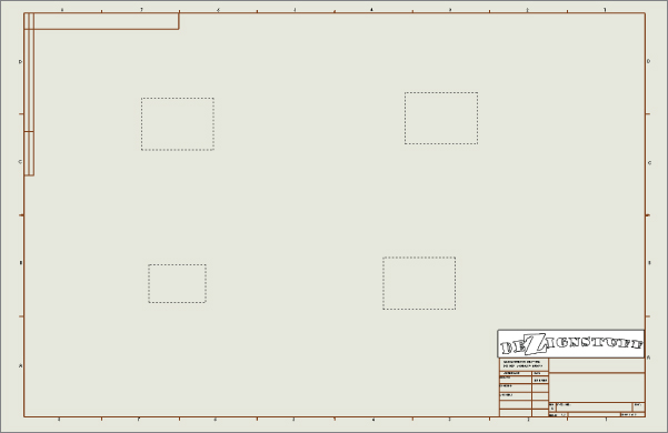
FIGURE 24.20 Predefined views on a template
After a predefined view has been placed, you can select an orientation for it from the PropertyManager. Figure 24.21 shows the Drawing View PropertyManager. The orientation for a view is set in the top Orientation panel. In addition to orthogonal views, you can also create isometric and other custom views as predefined views.
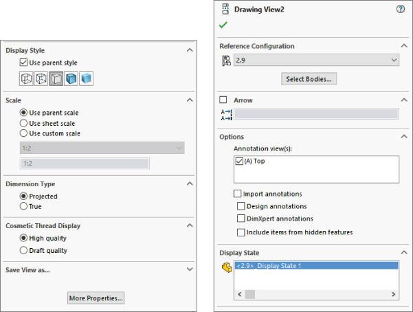
FIGURE 24.21 The Drawing View PropertyManager
After the view has been oriented, you may want to create more views on the drawing that also become populated by model geometry. This is where the projected views are used. Make sure that the drawing properties are set to the correct projection angle.
Because the rest of the views have been created relative to the front view, none of the views need to be rotated as they would if, for example, the top view had been placed above the back or right view.
Although it isn't on this drawing, many drawing templates include a Third Angle Projection symbol as a part of the title block, which is in the format. Figure 24.1 at the beginning of this chapter shows First Angle and Third Angle Projection symbols. They are included as blocks with the sample data in the SolidWorks installation. Blocks are discussed in more detail in Chapter 16, “Working with Assembly Sketches and Layouts.”
ALIGNING PREDEFINED VIEWS
You can align views to one another through a view's RMB menu, as shown in Figure 24.22. Projected views are aligned to one another automatically, but if you chose to use a predefined view rather than a projected view to one side of the original predefined view, you can use the Align Vertical By Origin or the Align Horizontal By Origin command. This ensures that the parts in each view are aligned. Aligning by center should not be used for projected views on an engineering drawing, because it isn't guaranteed to line up the edges in adjacent views.
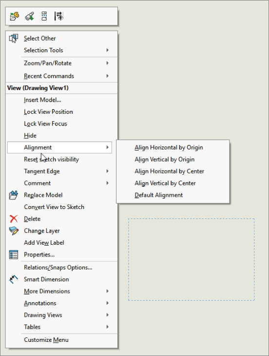
FIGURE 24.22 Selecting view alignment options
POPULATING A DRAWING WITH PREDEFINED VIEWS
Four methods exist to populate a drawing with predefined views:
- Drag-and-Drop: Drag a part or assembly from the FeatureManager and drop it in the drawing window. All predefined views are automatically populated.
- Insert Model: Right-click a view and then select Insert Model. From the interface, browse for the model to be displayed in all the related (projected) views.
- PropertyManager: Select a predefined view, and from the PropertyManager, select Browse in the Insert Model panel.
- Make Drawing from Part/Assembly: Click the Make Drawing From Part/Assembly button in the Standard toolbar, and select a template that uses predefined views.
SCALING PREDEFINED VIEWS
When predefined views are created, they are set to follow the sheet scale by default; however, you can manually set them to have a custom scale. If you are using the automatic scaling option (found at Tools ➢ Options ➢ System Options ➢ Drawings ➢ Automatically Scale New Drawing Views), the sheet scale is automatically changed when the drawing views are populated to make a nice fit of the model geometry on the drawing. The scales used by the automatic feature are all standard multiples of two, so you don't have to worry about odd scale factors on your drawings.
UNDERSTANDING THE LIMITATIONS OF PREDEFINED VIEWS
The function and expectations of predefined views are fairly straightforward, although a few things could be improved. For example, SolidWorks doesn't allow you to create predefined section or detail views. Also, the View palette doesn't preview the populated predefined views.
Using Styles and Blocks in Templates
In SolidWorks, styles function like favorites for notes and dimensions. You can also think of them as working like styles and formatting in Microsoft Word, or other word-processing software, by controlling text formatting, tolerances, and symbols.
An example of a style would be to add +/-0.005″ to the end of any dimension with the selected style.
Styles can be saved to files and loaded to documents. In particular, they can be loaded to documents that can be saved as templates, thereby maintaining the loaded styles. Several types of styles can be loaded into and saved with drawing templates, including dimension, note, GD&T (geometric dimensioning and tolerancing), weld, and surface finish symbols.
When a style is loaded into a template, any document that you create from that template can use any of the loaded styles. The many file types for styles exist mainly to transfer styles from one document to another, but they aren't needed after the style is loaded. As a result, before saving a template, you should gather together your styles into your library folder and load them into the template.
You can load styles by going to the interface for the type of favorite—for example, dimensions or notes. Figure 24.23 shows the top of the Note PropertyManager interface, which contains the Style panel.
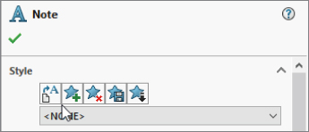
FIGURE 24.23 The Style panel for the Note PropertyManager
The buttons in the Style panel of the Note PropertyManager interface have the following functions, from left to right:
 Apply the default attributes to the selected notes.
 Add or update a style.
 Delete a style.
 Save a style.
 Load a style.
This section is concerned with loading a style. After clicking this button, you can load multiple styles at once by Shift+selecting them through the Open dialog box that appears.
Even symbol types that can be applied by dragging and dropping from the Design Library can also be loaded as styles. However, I prefer dragging from the Design Library because you get a preview of the symbol; with the styles, you see only a text tag.
Blocks can also be loaded into a template or used from the Design Library as drag-and-drop items.
Using Custom Properties in Templates
Part of the usefulness of templates is that you can do work once and have it replicated many times. This is an excellent example of process automation. One of the ways that you can take advantage of this feature is by putting default custom properties in your templates. In many cases, simply having a default value for something is better than no value, and a default value may even prompt you to put a value with real significance in the property. For example, the description of a document is extremely important, especially if you're using sequential part numbers for your filenames. A custom property named Description can be added to your template, and the default value will be used unless it's changed when the template is used in a document.
You have already seen how custom properties used in parts can be instrumental in filling out a title block on a drawing. Custom properties in part and assembly documents work exactly the same as they do in drawings.
Saving a Template
To save drawing templates, choose Save As ➢ Files Of Type and then select Drawing Templates from the drop-down list. This automatically takes you to the folder for the templates, as specified in Tools ➢ Options ➢ File Locations ➢ Templates.
You may also save out the format to its own file from the edited template. Formats are needed in their own file (in addition to existing within a template) for situations when you have an existing drawing and want to change the size of the sheet and then need a format to put on the sheet. Another situation is when a drawing may come in to your organization from an outside contractor, and they have not used your format; in this case, you can simply replace their format with yours, or you can send them your format (and template, for that matter), from which the contractor can create all the drawings for you.
Separate formats are important when you have multi-sheet drawings. When adding a sheet, you also need to add a format. You can save multi-sheet drawing templates in which the first and second sheets have different formats on them.
Creating Blocks
Blocks are an important aspect of automating drawing creation. They enable you to combine text and sketch geometry and to annotate common features on drawings. Blocks are discussed in Chapter 3, “Working with Sketches and Reference Geometry,” and Chapter 16, “Working with Assembly Sketches and Layouts.” Blocks can be used for many purposes, including the following:
- Tolerance blocks on drawings that might change with the process (if you don't have separate formats that already contain this information)
- Electrical or pneumatic schematic symbols that can be snapped together
- Flowchart type symbols
- Fluid flow-direction arrows
- Special markers calling attention to a specific detail
- Sheet formats that can be created as a block, enabling you to move it around as a single entity much more easily
You can create blocks by selecting a group of sketch entities, annotations, or symbols and then choosing Tools ➢ Block ➢ Make.
The Bottom Line
Getting your templates and formats correct creates an excellent opportunity to save some time with drawings by automating many of the common tasks using templates, predefined views, multiple formats, blocks, favorites, and linked custom properties. Setup becomes more important when you are administering a larger installation, but it is also important if it's just for yourself. One of the most important things you can do is to establish a file library and direct your Tools ➢ Options ➢ File Locations paths to the files. There's nothing quite as productive as having something that works right the first time and every time.
- Master It Create formats for size A and B drawings. Copy them from existing DXF or DWG data, and modify them for your needs. Save as
*.SLDDRTfile type.Use the title block functionality to create an editable block of manually filled-in annotation in the format.
- Master It Set up a drawing template with the custom properties such as Revision, DrawnBy, ReleaseDate, and other properties that you can use to automatically fill out fields on your title block. Also, place one predefined view and a couple projected views.
Make sure that you save an appropriately sized format with your template, such that the template is sheet size specific.
- Master It Create a second page format with simplified title block and place it in a two-page drawing template. Make sure you have stand-alone copies of the formats in case you have a situation where you need to update the formats in drawings.