Chapter 27
Dimensioning and Tolerancing
Dimensioning and tolerancing is an art form as much as a science. People become very passionate when discussing the right way to perform these tasks. In truth, the techniques are not so black and white, but are highly dependent on the industry, the means of manufacture, and the purpose of the drawing. Drawings might be used for quotes, manufacturing, inspection, assembly, testing, and so on; and the drawings, as well as the dimensioning and tolerancing used, for each purpose might need to be somewhat different in each circumstance.
Although it's important to follow standards and use drawing conventions properly, I have never seen any company follow an ANSI standard 100 percent—and this is not an argument that I want to reignite here. In this chapter, I focus on how the available tools work. You need to decide for yourself how to apply them in each situation.
Putting Dimensions on Drawings
The debate on how to get the dimensions from the model to the drawing is much like the “tastes great/less filling” debate. Each side of the issue has valid points, and the question is not likely to be resolved anytime soon.
At the center of this debate is whether you should place the dimensions that you use to create the model directly on the drawing or whether you should use reference dimensions created on the drawing. In the following sections, I will examine each method for its benefits and drawbacks.
Using Insert Model Items
 Insert Model Items takes dimensions, symbols, annotations, and other elements that are used to create the model and puts them onto the drawing. Because these dimensions come directly from the sketches and features of the model, they are driving dimensions. This means that you can double-click and change them from the drawing the same way you can change sketch and feature dimensions—and with the same effect. As a result, changing these dimensions even from the drawing causes the parts and assemblies in which they are used to be changed.
You can insert the model items in several ways: on a per-feature basis, bringing only the items that are appropriate into the current view, or bringing items into all views. Insertion can be further broken down by type of item, and it can become as specific as pattern counts, Hole Wizard items, specific symbol types, and reference geometry types. To use Insert Model Items, you can choose Insert ➢ Model Items, or you can access this command from the Annotations toolbar. The Model Items PropertyManager interface is shown in Figure 27.1.

FIGURE 27.1 The Model Items PropertyManager interface
Often, the dimensions need to be rearranged to some extent, although SolidWorks does try to arrange them so they don't overlap. Figure 27.2 shows the result of bringing dimensions into all views for the part. The part is in the download materials for Chapter 27.

FIGURE 27.2 The default placement of dimensions into all views
Figure 27.2 contains duplicate dimensions, overlapping dimensions, unnecessarily long leaders, radius dimensions pointing to the wrong side of the arc, dimensions for features you can't see, and lots of awkward placement. This is what you can expect from using the automatic functions. At best, these dimensions need to be rearranged, and a new view needs to be created; at worst, they probably require that you delete and replace dimensions as needed.
You can also import dimensions to specific features in specific views, in which case you would wind up going through the process several times to get the dimensions you need in the views where they are needed. If your company standards require that you must use driving dimensions on your drawings, this is probably the most successful route for you to follow.
To move a dimension to another view, you can Shift+drag it from one view to the other (make sure the dimension is appropriate in the destination view). To copy a dimension, you can Ctrl+drag it. If you cannot place the dimension in the view to which you have dragged it, the cursor will indicate this with a special cursor symbol.
If you approach this task by placing dimensions on a per-feature or per-view basis, it won't change the number of dimensions you must move; it will just mean that you will insert fewer dimensions several times. Keep in mind that if you choose this method, you must perform a significant amount of cleanup and checking. The convenience of having the dimensions put into the views for you and the ability to actually change the model from the drawing are quite useful, but you may not save very much time or effort by doing things this way.
If you design your parts with the same dimensions that will be used for the drawing, inserting model items is definitely the way to go. If your dimensions are driven by parametric or modeling needs, you may be better served by reference dimensions.
The standard ANSI Y14.41 calls for manufacturing dimensions—PMI, or product manufacturing information—to be attached directly to the 3D model. While this standard may not be evenly implemented across all industries, some manufacturers are making use of it now. 3D Views can be placed on SolidWorks drawings, and PMI information can be attached to these views. The complete functionality is found in SolidWorks MBD, which is a separate add-in package and, therefore, beyond the scope of this book.
Using Reference Dimensions
 One alternative to automatically inserting all model dimensions is to manually place reference (Smart) dimensions. You create reference dimensions by using the regular Smart Dimension tool. At first, this appears to be simply re-creating work you have already done, and this is somewhat true, but there is more to the story.
These dimensions are not duplicates of the model items. In fact, the reference dimensions that you manually place on the drawing are completely different from the dimensions used in the model. The dimensions serve completely different purposes in the two settings.
When modeling, I tend to dimension in a way that is best for modeling, which is not what would be shown on a manufacturing or inspection drawing. I frequently use workarounds to avoid some special problem that would force a different model dimensioning scheme than I prefer to use. Often, a feature is located from the midpoint of an edge, which involves no dimensions whatsoever. Sketch entities may have Equal relations, which also leave sketch elements undimensioned, but still fully defined. Dimensions may lead to faces or edges that are not in the final model or to faces that are later changed by scale, draft, or fillets. Beyond that, when draft is involved, as is the case with plastic or cast parts, the dimensions of the sketch that you used to create the feature often have little to do with the geometry that is dimensioned on a print for inspection or mold building. Dimension schemes in models reflect the need for the model to react to change, while dimension schemes in drawings reflect the manufacturing or inspection methods in order to minimize tolerance stack-up and to reflect the usage of the actual part.
Although there are strictly technical reasons for dimensioning drawings independently from the way the model was dimensioned, there are other factors such as time and the neat and orderly placement of dimensions. Time is an issue because by the time you finish rearranging dimensions that were inserted automatically from the model—checking and eliminating duplicates and then manually adding dimensions that were left out or that had to be eliminated because they were inappropriate for some reason, as well as ensuring that all the necessary dimensions are on the drawing—it would have been much quicker to manually dimension the drawing correctly the first time using reference dimensions.
In most cases, inserting model dimensions into the drawing is impractical for manufacturing or inspection drawings unless you have simple plates with machined holes, or you have taken extreme care to make sure your model is dimensioned the way you would represent it on the drawing. This is because of the amount of time required to rearrange and check the dimensions, the need to ensure that you have placed the necessary dimensions and taken geometric tolerancing into account, and the simple fact that the dimensioning and sketch relations needed for efficient modeling are usually very different from the dimensioning needed for manufacturing or inspection.
I recommend that you use the manual reference dimension placement option, which works in much the same way as when dimensions are added to sketches. Dimensions that you place in the drawing in this way are called driven, or reference, dimensions. In drafting lingo, reference dimensions are usually shown with parentheses around them because they are duplicated in some way. In SolidWorks, reference dimensions are simply driven rather than driving dimensions. To find the setting that controls the parentheses around reference dimensions, choose Tools ➢ Options ➢ Document Properties ➢ Dimensions ➢ Add Parentheses By Default.
RAPID DIMENSION
Rapid Dimension offers a manipulator wheel that shows the possible locations of a dimension you are trying to place.
Rapid Dimension works for dimensions inside drawing views, not on dimensions on the sheet. It enables you to choose from either two or four options, and you can move between the options with the Tab key, making your selection with the spacebar. You can also click the manipulator to select an option. In Figure 27.3, the Rapid Dimension manipulator wheel is shown placing the diameter and linear dimensions.
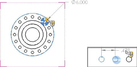
FIGURE 27.3 Placing dimensions with the Rapid Dimension manipulator wheel
The tool does have some limitations, however. It doesn't seem to be capable of handling combined aligned dimensions or horizontal and vertical dimensions. For example, if you dimension an angled line, Rapid Dimension would only allow a dimension that's aligned to the angled line. If you dimension between the diagonal corners of a rectangle, it wouldn't allow you to place the diagonal dimension, only the horizontal and vertical dimensions.
You can disable the Rapid Dimension manipulator and control some of the other dimensioning assistance tools in the Dimension PropertyManager. This might lead to some confusion, because it seems that there are three separate Dimension PropertyManagers. The one I am talking about here is the PropertyManager that appears when the Dimension tool is active in the drawing. You see a different PropertyManager when the Dimension tool is active in the part and another one when you select an existing dimension on the drawing.
REFERENCE DIMENSIONS AND THE DIMXPERT
I've already made the case for why I think it's better to use reference dimensions on the drawing than model dimensions. This is opinion, of course, and I realize that for many simple parts, you actually can model them the way you would detail them, so the model items make more sense in those cases. Many respectable power users insist on using model items on drawings.
Consensus from my own experience and from users I have talked to at companies, user groups, and the forums indicate that this functionality is a work in progress (which was added over 10 years ago). Although it may offer some interesting functionality, it may not save you any time when dimensioning and tolerancing parts on a drawing. It seems that it has particular difficulty with molded or cast parts, which typically don't have parallel faces.
The DimXpert is really meant to dimension 3D parts (with nondriving dimensions), and that scheme is meant to be used as your ASME Y14.41 3D model-based definition to alleviate dependence on detailed 2D drawings and establish the 3D model through the use of 3D PDF or STEP AP 242 as a drawing standard. The use of DimXpert is, therefore, not really appropriate for 2D drawings, although SolidWorks does offer 2D DimXpert functionality. I have yet to meet any SolidWorks users, aside from SolidWorks employees, who are very enthusiastic about the current implementation of DimXpert.
ANNOTATION VIEWS
Annotation views are views in the model in which annotations have been added. You can access annotation views from the Annotations folder in the model FeatureManager. They are created automatically when you add dimensions or notes to the part. You can use the annotation view in the model to show the note or dimension in the view in which it was created or on the drawing to help parse the dimensions into views where they are easily read.
Annotation views can be inserted manually or automatically. You can access the settings for annotation views through the right mouse button (RMB) menu of the Annotations folder of the model, shown in Figure 27.4. The image shows part of the PropertyManager you get when inserting a named view on a drawing. It shows that the front and top views of the model have annotations associated with them (indicated by the A on the view symbol).
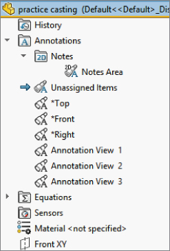
FIGURE 27.4 The Annotations folder RMB menu
DRIVEN DIMENSION COLOR
Driven dimensions on the drawing display in gray, and this can be a problem when the drawing is printed. You can use two methods to deal with this printing problem. The first method is to set the Page Properties of the drawing to force it to print in black and white rather than color or grayscale. To find the Page Properties, choose File ➢ Page Setup. The Page Setup dialog box is shown in Figure 27.5.
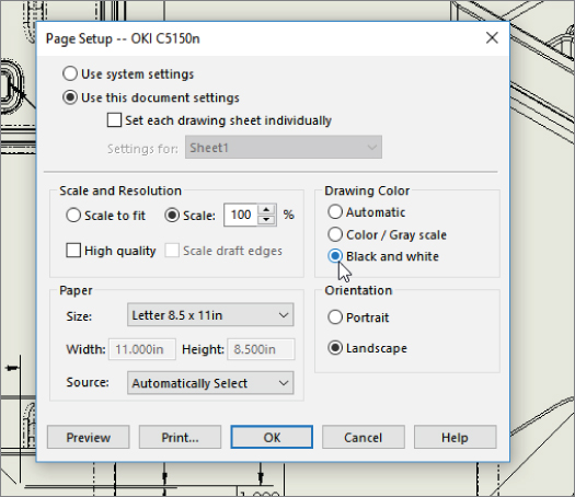
FIGURE 27.5 The Page Setup dialog box
The second method is to set the color for driven dimensions to black (or another dark, saturated color such as dark blue) rather than gray. You can find this color setting by choosing Tools ➢ Options ➢ Color ➢ Dimensions Non-Imported (Driven).
ORDINATE AND BASELINE DIMENSIONS

 Ordinate and baseline dimensions are appropriate for collections of linear dimensions when you have a number of items that can all be dimensioned from the same reference. Flat patterns of sheet metal parts often fall into this category. When you apply ordinate dimensions, a zero location is selected first, followed by each entity for which you want a dimension. When dimensions become too tightly packed, SolidWorks automatically jogs the witness lines to space out the dimensions adequately. You can create jogs manually by using the RMB menu. After you create a set of ordinate dimensions, you can add to the set by selecting Add To Ordinate from the RMB menu.
Baseline dimensions are normal linear dimensions that all come from the same reference and are stacked together at a defined spacing. To find the default settings for baseline dimensions, choose Tools ➢ Options ➢ Dimensions ➢ Offset Distances.
Baseline dimensions work best either when they are horizontal or when the dimension text is aligned with the dimension line (as is the default situation with the ISO, standard dimensioning). Vertical dimensions where the text is horizontal don't usually stack as neatly, because the dimension text runs over the dimension line of the adjacent dimensions. Figure 27.6 shows ordinate and baseline dimensions in the same view.
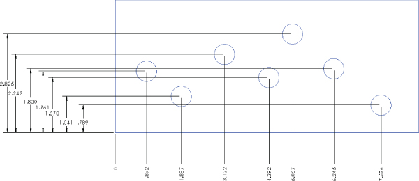
FIGURE 27.6 Ordinate and baseline dimensions in the same view
You can access ordinate and baseline dimensions from the Dimensions/Relations toolbar or by right-clicking in a blank space, selecting More Dimensions, and then selecting the type of dimension that you want to use.
AUTODIMENSIONING
If the Insert Model Items feature is not likely to produce dimensions that are usable in a manufacturing drawing, then the Autodimension feature is even less likely to do so. However, if you use autodimensioning in a controlled way, in the right situations, it can be a valid way to create selected dimensions. The Autodimension PropertyManager is shown in Figure 27.7. Autodimension is available only in the drawing environment. In the part environment, similar functionality for sketches is part of the Fully Define Sketch tool. To access Autodimension, click the Smart Dimension toolbar icon and then click the Autodimension tab in the PropertyManager.
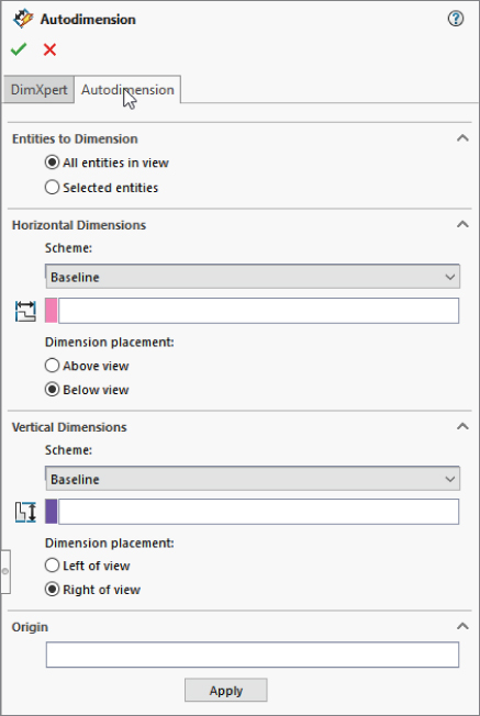
FIGURE 27.7 The Autodimension PropertyManager interface
The Autodimension function can fully dimension the geometry in a drawing view. This is best for ordinate or baseline dimensioning where many dimensions are derived from a common reference, as is often the case with sheet metal parts or a plate with many holes drilled in it. You should limit the use of this option. Don't allow the software to dictate the dimensioning scheme for your drawing.
REFERENCE SKETCHES
For some types of dimensions, you may need to create additional reference sketch entities. For example, with angle dimensions, it may be desirable to add construction lines or points to help define the angle. You can add centerlines as separate axis-like entities, but you can also sketch in centerlines manually if needed. This type of sketch is most often attached to the view rather than the drawing sheet.
Understanding Dimension Options
The Dimension PropertyManager contains settings, default overrides, tolerances, styles, and several other important settings for use with dimensions. The PropertyManager for driven dimensions is shown in Figure 27.8. I will cover styles and tolerances specifically later in this chapter; the other tabs of the Dimension PropertyManager are discussed in this section.

FIGURE 27.8 The Dimension PropertyManager interface
DIMENSION TEXT
The Dimension Text panel enables you to add text to the dimension. You can add lines of text both above and below the dimension value itself, and you can add text before and after the DIM value on the same line. The DIM field is what places the actual value; if this syntax is somehow deleted, you can type it back in and the dimension will still work.
The Dimension Text panel includes some formatting tools, such as justification settings and a setting for the position of the dimension line. The last two rows of buttons include the more commonly used symbols, with access to the complete library, such as any custom symbols that you may have made for the library.
PRIMARY VALUE OVERRIDE
The most infamous habit that former AutoCAD users have is overriding dimension values. Apparently due to popular demand, the Primary Value Override is now available in SolidWorks, in the Dimension PropertyManager, as shown in Figure 27.8. This option was added to the software mainly to enable the creation of dimensions with words instead of numbers, as shown in Figure 27.9.
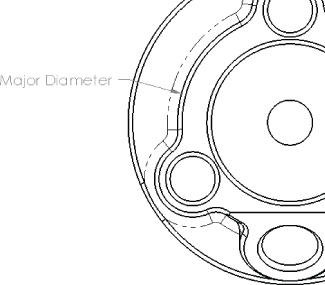
FIGURE 27.9 Using the Override Dimension value
DISPLAY OPTIONS
You can control the default setting for parentheses around driven (reference) dimensions in the Add Parenthesis By Default dialog box by selecting the choosing Tools ➢ Options ➢ Document Properties ➢ Dimensions ➢ Add Parentheses By Default.
Although you can also control dual dimension defaults in the Options dialog box by choosing Tools ➢ Options, you can turn them on and off from this interface for individual dimensions. When you enable the Dual Dimension option, SolidWorks uses the settings from the Tools ➢ Options menu.
The foreshortened radius is valid only for individual radial dimensions. A foreshortened radius is shown in Figure 27.10. Foreshortened radius dimensions are typically used for large radii when dimensions to the centerpoint are not important. The Foreshortened radius function does not work on diameter dimensions. The inspection dimension is shown in Figure 27.10 with an oval around the dimension.
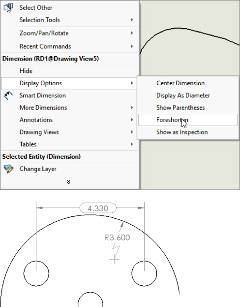
FIGURE 27.10 A foreshortened radius
You cannot foreshorten a diameter directly; however, you can create a foreshortened radius and change it to a diameter, or dimension a diameter and then hide the extension line and dimension line in one direction. This option is found by right-clicking both the extension line and dimension line. The RMB menu includes options to hide the extension line and hide the dimension line. This is useful if you have a diameter dimension in a detail view where the opposite side of the diameter is outside the detail view. This can also be used for linear dimensions that terminate to a known end outside the drawing view.
WITNESS/LEADER DISPLAY
This panel enables you to set the arrows and dimension lines to be placed inside the witness lines. You can perform this function more easily by using the handles on the arrowheads. From this panel, you can also change the display type of individual arrowheads.
BREAK LINES
When you select the Use Document Gap option in this panel, the witness, or extension, lines of the selected dimension are broken by other crossing dimension lines, witness lines, or arrows. This is shown in Figure 27.11.
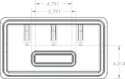
FIGURE 27.11 Broken witness lines
FORMATTING DIMENSIONS WITH THE DIMENSION PALETTE
 When you select a dimension on a drawing (the dimension can be a model item or a reference dimension), a small symbol will appear above and to the right of the dimension. If you click the symbol, the Dimension palette will expand. The Dimension palette enables you to do the following:
- Add tolerances
- Specify dimension precision
- Assign styles (favorites)
- Apply parentheses
- Center the dimension between the witness lines
- Apply inspection dimension
- Offset the text with a leader
- Establish horizontal and vertical justification
- Add text on top of, before, after, and below the dimension value
The Dimension palette appears when you select a dimension and disappears when you move the cursor away from it. The Dimension PropertyManager still appears, but the Dimension palette pops up right next to the dimension, making it very easy to use. Figure 27.12 shows the Dimension palette.
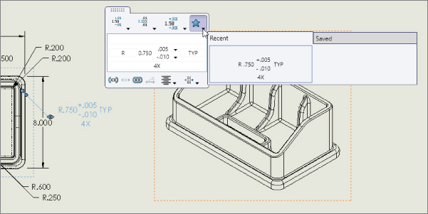
FIGURE 27.12 Adding text and tolerances to dimensions using the Dimension palette
The Dimension palette seems to be the most convenient place to make these alterations to the basic dimension itself. Also, don't forget the Format Painter to copy dimension formatting to multiple other dimensions.
Adding Tolerances
You can add dimension tolerances in the Dimension PropertyManager or the Dimension palette as discussed earlier, which you can activate by selecting the dimension that you want to modify. These tolerance types are available:
- Basic
- Bilateral
- Limit
- Symmetric
- MIN
- MAX
- Fit
- Fit With Tolerance
- Fit (Tolerance Only)
Refer to the Tolerance/Precision panel shown in Figure 27.8. The appropriate fields for entering numbers are activated when you assign the corresponding tolerance type to the dimension. The tolerance types that are available in SolidWorks are shown in Figure 27.13.
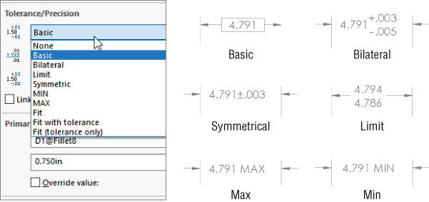
FIGURE 27.13 The available tolerance types in SolidWorks
In addition to these tolerance types, SolidWorks offers a range of Fit tolerances from C8 through X7, as shown in Figure 27.14.

FIGURE 27.14 The Fit tolerances available in SolidWorks
Changing Precision Values
In SolidWorks, precision means the number of decimal places with which dimensions are displayed. Typically, SolidWorks works to eight places with meters as the default units. You can create templates that use up to eight places as the default setting and then change the number of places for individual dimensions as necessary. The first of the two boxes under Precision is used for the dimension precision, and the second is used for tolerance precision.
You can change Precision values for individual dimensions in the PropertyManager for the dimension as well as the entire document by choosing Tools ➢ Options ➢ Document Properties ➢ Units.
Using Geometric Tolerancing Symbols
The full range of Geometric Tolerancing symbols is available for control frames, datums, datum targets, and so on. You can use the Geometric Tolerance dialog box to build control frames. This dialog box is shown in Figure 27.15. For commonly used Geometric Tolerance symbols, you may want to create and use styles.
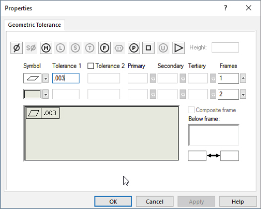
FIGURE 27.15 The Geometric Tolerance settings
I'm not pretending to teach GD&T tolerancing in this chapter, I'm just presenting the tools SolidWorks provides to help you make it happen. The SolidWorks tools were created in step with the appropriate U.S. and international drawing standards. If your company follows somewhat different practices, or you feel you cannot meet your requirements with these tools, I can suggest a couple of things. Before you do anything drastic, you should pull together expertise on both sides of the issue. Sit down with a SolidWorks GD&T expert and an industry GD&T expert along with your own company's standards expert to understand where the real differences lie.
- Get as close to your requirements as possible with the tools available.
- Alter your requirements to match the capabilities of the tool.
- Get another tool that meets your requirements.
Counting on SolidWorks changing the software to meet your drafting requirements is probably not going to be productive, unless you can show that SolidWorks has misinterpreted the ASME or ISO standards, and even if you can, that may take some time. Just to be practical, some flexibility may be required to keep your drawing production moving along without reinventing either your process or replacing the tools you use in your process. I have never been to a single company that really follows any of the standards 100 percent. There is always some local customization.
Using Dimension Styles
You can use dimension styles to apply many items to dimensions. Styles were formerly known as favorites in SolidWorks. Unlike notes, dimension styles are not limited to fonts and formatting. Here are some of the most common uses for dimension styles:
- To add standard tolerances to dimensions
- To set precision values for dimensions
- To add text, such as TYP, to a dimension
- To add a commonly used GD&T (geometric dimensioning and tolerancing) reference
You can save styles from one document and load them into another document, even between document types. For example, you can load part dimension styles into a drawing.
When a style is updated from an external file, any document that it's linked to also updates the next time it's opened. In addition, you can break links to external styles (with the appropriate button on the Styles panel). Otherwise, dimension styles have very similar functions to the other types of styles; the functions of all the buttons on the Styles panel are the same.
Aligning Dimensions and Annotations
When you place dimensions and annotations on a drawing, it is nice to have them lined up in an orderly way. Drawings contain lots of information, and that information must be easy to read. Keeping items lined up in horizontal and vertical alignment is one of the keys to making the information on a drawing easily accessible.
SolidWorks has a toolbar just for the alignment of dimensions and annotations. The toolbar is shown with labels for individual icons in Figure 27.16. To add the Align toolbar to the CommandManager, right-click one of the CommandManager tabs and select Customize CommandManager. Then click the new tab that appears and select the Align toolbar from the list.

FIGURE 27.16 Using the tools from the Align toolbar
Using the Alignment Tools
The alignment tools are all preselect tools, so it's best to box select (or Ctrl+select) the dimensions and annotations you want to align first and then click the toolbar icon. For example, to align a set of balloons to the right, you would drag a box around the balloons, Ctrl+select any balloons you couldn't select with the box, and then click the Align Right button (although ideally with balloons, you can use Magnetic Lines). These tools work best with larger selections of dimensions or annotations. For aligning individual dimensions or pairs of dimensions, it might be better to use the drag methods discussed in the next section “Inferencing Alignment and Grid Snapping.”
Using the Align Collinear/Radial and Align Parallel/Concentric alignment tools creates persistent relationships, so those dimensions aligned with the tools will maintain that alignment. The other tools on the Align toolbar don't work this way. To break an alignment created by these tools, select Break Alignment from the RMB menu.
Using the Group tool allows a set of dimensions and annotations within a single view to maintain their spatial relationships. They remain in those relative positions until they are ungrouped.
Inferencing Alignment and Grid Snapping
When you drag individual dimensions on a drawing, they are snapping to a grid. (Annotations don't snap to the grid.) This is one way that SolidWorks helps you to align them. If you drag one dimension level with another, either horizontally or vertically, a line appears and the dimension inferences the position of the other dimension, just like lines snapping in model sketches.
Annotations will inference other annotations, but they won't inference dimensions, and they won't snap to the grid.
If you want to disable both kinds of snap (grid and inference) on the fly, just hold down the Alt key while dragging, and the dimension or annotation will slide freely. To permanently disable the snapping, go to Tools ➢ Options ➢ Drawings ➢ Disable Note/Dimension Inference. To disable the snap, make sure this option is selected. You should be aware that this option controls both the snap to the grid and the inferencing of one dimension or annotation to another. You cannot separate the grid from the inferencing.
If you like the snaps and want to change the spacing, you can do that by selecting Tools ➢ Options ➢ Document Properties ➢ Dimensions ➢ Offset Distances and changing the appropriate numbers for the distance of the dimension from the edge of the part and the distance between dimensions.
If you want a group of dimensions or annotations that you have aligned to maintain their current alignment, box select them and use the Group function from the Align toolbar. All of the selected dimensions and annotations must belong to the same view.
Using Dimension Palette Alignment Options
The Dimension palette, mentioned earlier in this chapter, enables you to surround a dimension with all the necessary information, such as additional text, tolerances, symbols, justification, leader control, dual dimension display, and other useful information. It can also perform some alignment functions. If you multi-select dimensions and activate the Dimension palette, you will see what is shown in Figure 27.17. In this case, the Dimension palette is used to apply the Align Stagger function to a set of vertical dimensions to pack them close to one another. This function isn't found on the Align toolbar. However, notice that it also has some of the Align toolbar functionality, including bottom, top, left, and right justification. The functions have different names and symbols in the Dimension palette than in the Align toolbar, but they appear to do the same thing.
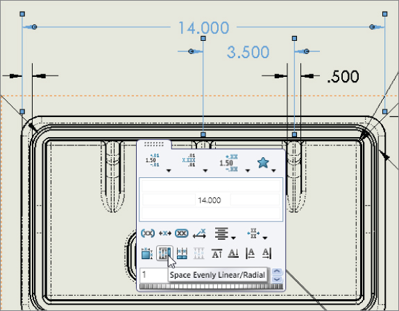
FIGURE 27.17 Selecting alignment options from the Dimension palette
The Dimension palette is one of my favorite tools in SolidWorks drawings because it consolidates lots of functionality into a small space that's available right where you need it. When it was originally released, many users thought it got in the way, but the small activation icon solved that problem, and the functionality has only improved.
Arranging Dimensions Automatically
Every few releases, SolidWorks improves the automatic dimension-arranging tools. But to me, they have a long way to go before I will trust them to arrange dimensions on a large drawing, where they would offer the most benefit. Sometimes, they do a good job on simple rectangular parts, but they don't save much time on the complex parts.
When you put model items onto a drawing, SolidWorks automatically arranges the dimensions. The alignment option on the left side of the Dimension palette is called Auto Arrange Dimensions. Also, when you use the Autodimension function mentioned earlier in this chapter, SolidWorks automatically arranges the dimensions for you.
The best way to use these tools with dimensions and general annotations is in small, controlled situations until you learn how they react to the type of work you tend to do frequently. Selecting items in groups that are close to where they need to go will help the automatic tools do a better job.
Tutorial: Working with Dimensions and Tolerances
In this tutorial, you can use a single part in several different ways to demonstrate different dimensioning and tolerance functions. Follow these steps to learn more about these topics:
- Open the part from the download material called
Chapter 27 Tutorial.sldprt. - Open the drawing from the download material called
Chapter 27 Drawing.slddrw. - Tile the windows by choosing Window ➢ Tile Vertically, and drag the part from the top level of the FeatureManager into the drawing window. This will automatically populate the four drawing views.
- Delete the top view, leaving the views as shown in Figure 27.18.
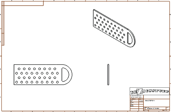
FIGURE 27.18 The drawing after step 4
- Choose Insert ➢ Model Items, and ensure that the Select All option is selected for Annotations and the Marked For Drawing option is selected for Dimensions. Also make sure that the Source/Destination drop-down list is set to Entire Model. Click the green checkmark icon and watch the drawing populate.
- The resultant drawing is quite cluttered. Delete and move dimensions so the drawing looks like Figure 27.19.
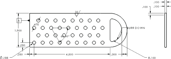
FIGURE 27.19 The drawing after dimensions have been deleted and moved
- Shift+drag the surface finish symbol to the right view, and do the same with the 1.900-inch dimension. You may have to first Shift+drag it into the other view and then drag it again to correctly attach or position it.
- Create a set of horizontal ordinate dimensions from the left end of the part and dimension the X position of each column of holes. Do the same for rows of holes, using the bottom edge of the front view as the zero reference. Remember that you can create ordinate dimensions by starting a normal Smart Dimension, right-clicking to display the More Dimensions list, and then selecting your choice.
- If necessary, add center marks and centerlines to the view for clarity.
- Select the .188 diameter dimension, and in the Dimension Text box, type TYP after the
<DIM>text, and add a bilateral tolerance of +.003, –.005. Save this as a style by clicking the Add Style icon. - Apply the newly created dimension style to the R.100 dimension. The results up to this step are shown in Figure 27.20.
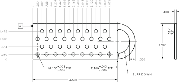
FIGURE 27.20 Dimensions and tolerances after step 11
- Make one of the dimension leaders for either the .188 or the R.100 dimension cross the extension lines of the 4.500 dimension. Then select the 4.500 dimension, and in its PropertyManager, select the Use Document Gap option in the Break Lines panel on the Leaders tab.
- Place a B datum marker on the circumference of the smaller arc on the left end of the part. Create a Geometric Tolerance control frame, as shown in Figure 27.21.
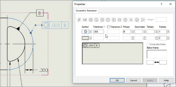
FIGURE 27.21 Creating a Geometric Tolerance control frame
- In the right view that shows the thickness, select the .100 dimension, and add a tolerance and a note below the text using the Dimension palette, as shown in Figure 27.22.
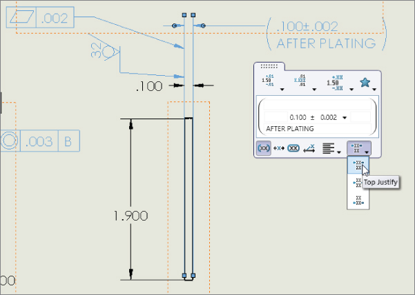
FIGURE 27.22 Using the Dimension palette
- Delete the last two dimensions of the horizontal ordinate group (3.837 and 4.076). Start a new detail view that includes the holes those dimensions called out, as shown in Figure 27.23. Place the detail view above the main view.

FIGURE 27.23 Adding more dimensions and annotations
- Right-click the zero for the horizontal ordinates, and select Add To Ordinate. Place the two ordinate dimensions in the detail view.
- Use the Geometric Tolerance tool to make a Flatness callout of .002. Add a leader to the control using the PropertyManager and attach the leader to the .100 thickness dimension in the right view.
The Bottom Line
The argument about how to set up and use dimensions on drawings is as old as the process of creating geometrical plans from which objects are built. It's often difficult to separate fact and best practice from opinion. Although I leave it up to you to decide these issues for yourself, this chapter is intended to help you understand how to create the type of drawing you want.
The biggest conflict in this subject arises over whether to place live model dimensions on the drawing or to allow the requirements of the drawing to specify which dimensions are placed where. I am by no means impartial when it comes to this question, but again, you must choose for yourself.
- Master It Create a drawing from the part called
Simple Part.sldprtin the download material for this chapter. In the front view, shown here, use the DimXpert to dimension the view.
- Master It Use the Dimension palette to add text and tolerances to some of the dimensions.
- Add +/- 0.005 to the 5.236 dimension.
- Select one of the hole callouts and replace the depth with the word THRU. Use the Dimension PropertyManager to do this.
- Box select the 3.141, 4.803, and 5.236 dimensions and make them inspection dimensions.
- Master It In the side view, use vertical ordinate dimensions to dimension some of the prominent features from that view.