In searching for economical and efficient solutions to the problems that have been posed, engineers seek effective exploitation of the mechanical properties of the materials that are being used: properties such as the stretchiness or stiffness (the change in dimensions as the material is subjected to changes in load) and the strength (the limit to the amount of load that can be supported). Through experience and understanding, engineers have become more adept at exploiting these properties in order to produce increasingly daring structures. Effective exploitation implies that civil engineers are able either to control these properties to suit the application or to understand the nature of the properties of the materials with which they are presented. For example, the steel and concrete that we see in structures above the ground can be designed to have chosen stiffness and strength. These are manufactured materials which may have to be transported a long way to reach a construction site. The costs of transportation may be regarded as excessive, and locally sourced wood and rock may be available instead – their strength and stiffness are as you find them. Rock is just one constituent of the more general range of materials that make up the ground. The softer materials are designated as soils though the boundary between weak rocks and hard soils is not well defined.
All civil engineering constructions sit upon or sit in the ground. Tunnels pass through the ground; foundations for buildings and bridges are excavated from the ground; aeroplanes land on the ground; motor cars and railway trains drive on roads or rails laid on the ground; and ships berth against structures which are attached to the ground. So the behaviour of the soil or other materials that make up the ground in its natural state is rather important to engineers. However, although it can be guessed from exploratory probings and from knowledge of the local geological history, the exact nature of the ground can never be discovered before construction begins. By contrast, road embankments are formed of carefully prepared soils; and water-retaining dams may also be constructed from selected soils and rocks – these can be seen as ‘designer soils’.
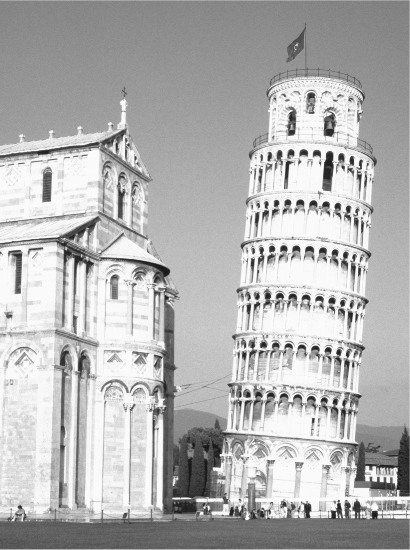
Today tourists flock to Pisa (Figure 1) not because of the fine Romanesque duomo but because of the unfortunate incident of the belfry (which has resulted in the area around the duomo being called the campo dei miracoli) – they come to see the leaning tower. Like the duomo, the tower is an example of Romanesque construction with semicircular arches round the lower storey and semicircular arcades of arches around each storey of the tower. The few window openings on the staircase which spirals round inside the wall are small. The bells are hung within the top storey. What went wrong?
Soils are formed of mineral particles packed together with surrounding voids – the particles can never pack perfectly. The mineral particles come from the erosion of rock: sands are formed of particles of quartz or feldspar formed by mechanical erosion; clay minerals are silicates and aluminates resulting from weathering of parent rocks under conditions of high temperature and humidity. It may be surprising that granite, which is naturally a very strong structural material, weathers to form the clay mineral kaolinite, used for making porcelain. Porcelain, after it has been formed and baked at high temperature, is once again very strong and brittle.
1. The tower of Pisa would not attract tourists if the foundation conditions had been more uniform. Recent removal of small quantities of clay from the foundation has stabilized the tilt
Clay particles are small – officially smaller than 2 microns (2 millionths of a metre) in size – but soils can contain a very wide range of particle sizes depending on the source material, the manner of the weathering process, and the nature of the transportation process to the present location. Fine particles can be carried by wind; coarser particles can be carried by water; ice in the form of glaciers slowly moving down hillsides can transport huge boulders which may be subsequently discovered when the ground conditions at a site chosen for construction are being explored.
The voids around the soil particles are filled with either air or water or a mixture of the two. In northern climes the ground is saturated with water for much of the time. For deformation of the soil to occur, any change in volume must be accompanied by movement of water through and out of the voids. Clay particles are small, the surrounding voids are small, and movement of water through these voids is slow – the permeability is said to be low. If a new load, such as a bridge deck or a tall building, is to be constructed, the ground will want to react to the new loads. A clayey soil will be unable to react instantly because of the low permeability and, as a result, there will be delayed deformations as the water is squeezed out of the clay ground and the clay slowly consolidates. The consolidation of a thick clay layer may take centuries to approach completion.
The site chosen for the construction of the belfry at Pisa, begun in 1173, provided a rather poor foundation. The irregular layering of two different clays gave rise to a variable time-dependent deformation under the foundation of the tower with the result that it started to tilt only a few years after construction had begun.
The 12th and 13th centuries were unsettled times in Italy with the different city states of Pisa, Genoa, Lucca, and Florence all vying for dominance. Battles demanded money and people, and so the construction of the belfry took second place. When the masons under the direction of Giovanni di Simone resumed construction in 1272 they introduced a curve in the vertical alignment of the tower so that the courses of stone were once again being laid horizontally. This stratagem proved inadequate and the tower continued, slowly, to tilt further. Construction stopped again in 1284 and the belfry was only completed in 1372. The top storey very obviously makes another valiant attempt to establish a properly vertical line.
A leaning tower may be a valuable draw for tourists but as the tilt increases, the tower becomes progressively less stable. The tilted loading tries to encourage additional tilt of the foundation. There are many leaning towers in Italy: the skyline of Venice contains an impressive collection. There were once more. The brick-built campanile of San Marco in Venice collapsed in 1902 and was rebuilt. In 1989 the civic tower in Pavia collapsed without warning, killing three people. It was leaning but not dramatically: failure may have occurred because of variable movements in the cement mortar in which its bricks were set or because of slow, time-dependent changes in the properties of the bricks themselves rather than because of foundation problems. But the failure of one leaning tower naturally raised concerns about the safety of another one.
In 1990, careful monitoring of the Pisa campanile showed signs that the tilt of the tower was accelerating and there were signs of distress in stonework on the down-tilt side. Of the possible options, the only realistic one was to make some intervention in order to safeguard the tower in its current tilted position. Tampering with the foundation of a structure which is on the brink of collapse carries the risk that it will in fact trigger that collapse. This daring decision was taken by an international committee of geotechnical engineers (civil engineers with a particular interest in the behaviour of the ground). Modest safety measures were installed in the form of lead weights on the up-tilt side of the foundation together with cables which could have provided some slight restraint if the tilt had started to accelerate. Then small chunks of clay were extracted from under the up-tilt side of the foundation until the tower had rotated backwards to the inclination which it had had in about 1838. Its lifetime was thus successfully extended.
At Pisa and other cathedrals timber was used to construct temporary access platforms and supporting structures to enable the masonry building to be completed. Timber provides the internal structure for the conventional roof that is seen from outside the duomo. Provided there are trees around, timber has the obvious advantage over stone of being easier to work with. It obviously has the disadvantage of being combustible. Few timber buildings remain from the Middle Ages or earlier and, where they do, there is the constant risk of destruction. The Great Fire of London of 1666 started in a baker’s shop and destroyed the old St Paul’s Cathedral and some 13,000 houses. Nearly an entire block of the city of Trondheim, Norway, was destroyed in December 2002 by a fire which started in the kitchen of a restaurant. Also, timber has a tendency to rot if it becomes permanently damp and is eaten by bugs of various sorts and has a tendency to warp as it seasons and takes up or loses moisture.
On the other hand, trees grow in a way which is structurally efficient. The root systems respond to the external loadings applied by the wind in order to anchor a tree to the ground, whereas the branches are sufficiently flexible to move under wind and other environmental loadings. The cross section of a tree reduces from the roots upwards and outwards as the forces required to sustain or resist the movements of the more distant parts of the tree themselves become smaller. Wood can support compression loads very effectively and can support tensile loads, provided they are applied parallel to the grain (along the branches). Inspection of the wounds left by a branch or a trunk splitting will reveal the very fibrous nature of the growth and hint at the way in which these fibres might be strong individually but become readily delaminated if the applied loads try to pull them apart. The shape of a tree – a trunk with a single branch – can be deliberately exploited to provide a single curved cruck for a house or barn.
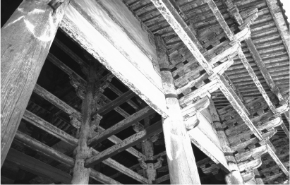
2. The great south gate (Nandaimon) of the Todaiji temple complex in Nara, Japan is typical of the use of ‘trabeated’ timber construction – beams and columns
The great south gate of the Todaiji temple complex in Nara, Japan, (Figure 2) was built in the 12th century at about the same time as many of the great Gothic cathedrals of Europe. The decoration is elaborate and serves to conceal some of the structural interconnections, with horizontal tie beams slotted through the main supporting vertical posts (a trabeated style of building). The detail of the substructures devised to permit the eaves of the roof to overhang as far as possible and to enable a high roof ridge, apparently two storeys up, to be formed over a single storey internal space shows great ingenuity. This was the product of cultural exchanges between Buddhists in Japan and China led by the priest Shunjobo Chogen who brought Chinese craftsmen to work alongside Japanese carpenters. Japan is, of course, a country of frequent earthquakes: timber structures such as these old temple buildings have enough flexibility in their joints to be able to withstand significant horizontal shaking without damage.
‘Hardwick Hall – more glass than wall’ was built by Robert Smythson for Bess of Hardwick in the 16th century, on a hilltop, as a deliberate statement of wealth and power. The individual panes of glass were small and irregular, the source of that dappled charm of old buildings, but the internal result was of great light. The Romanesque cathedrals such as Pisa give a feeling of solidity and security. The columns in the nave of Durham cathedral, in northern England, are more than 2 metres in diameter and security or even defence was often needed in those politically unstable times. But within a century or two the cathedral masons across Europe had learnt from experience how to exploit the properties of their primary building material, stone, in order to produce structures in which light – apparently in defiance of solidity – seems to be the most significant feature (although at many of the cathedrals one might think of colour rather than light since the enormous windows are usually filled with magnificent mediaeval stained glass).
Rock (or stone) is a good construction material. Evidently there are different types of rock with different strengths and different abilities to resist the decay that is encouraged by sunshine, moisture, and frost, but rocks are generally strong, dimensionally stable materials: they do not shrink or twist with time. We might measure the strength of a type of rock in terms of the height of a column of that rock that will just cause the lowest layer of the rock to crush: on such a scale sandstone would have a strength of about 2 kilometres, good limestone about 4 kilometres. A solid pyramid 150 m high uses quite a small proportion of this available strength. If the rock can be easily cut then it can readily be used for the carving of shapes and figures (but is also more likely to weather and decay).
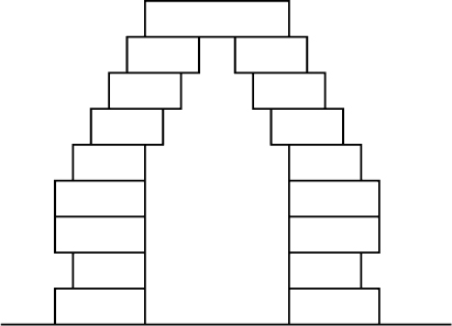
The builders of the Egyptian pyramids had the task of creating a massive rock structure around a small burial chamber. The small hole created local stress concentrations which they could relieve by leaning slabs of stronger stone against each other to form an internal pitched roof. Or alternatively they could create an internal protection by placing blocks of stone one on top of the other on each side of the void, projecting out (corbelling – see Figure 3) over the void gradually further and further until the void was closed by a stepped roof – much as one would if trying to create a bridge with children’s bricks to span a gap wider than the longest brick.
3. The builders of the pyramids in Egypt around 2600 BC used corbelling to bridge over internal burial chambers
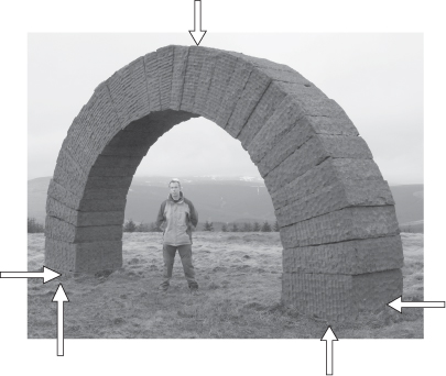
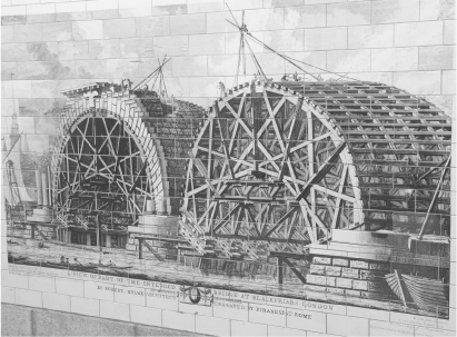
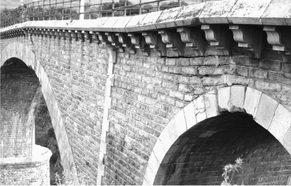
The Romans developed the semicircular arch as a structural form. An arch formed of a series of shaped voussoirs (carefully prepared wedge-shaped stones) is extremely strong once it is complete, provided it is able to push sideways against unyielding abutments (Figure 4). During construction the incomplete arch has to be supported using appropriate centring, usually made of wood (Figure 5). A little mortar on the radial joints between the voussoirs can provide some extra strength, but is not essential if the stones are carefully prepared. The centring is typically removed by pulling out carefully placed timber wedges. There is usually a little inevitable movement of the masonry as it takes up the load.
4. An arch converts vertical loads to a horizontal abutment thrust. This is one of Andy Goldsworthy’s ‘striding arches’ near Moniaive
When the centring for the Pont de Neuilly over the Seine just west of Paris was going to be removed in 1772, the engineer, Perronet, made sure that the centring for each of the five spans was removed simultaneously with a great splash in order to distract attention from the movement of the bridge which the crowds of spectators (including Louis XV) might otherwise have found a little disturbing. If the abutments move outwards a little, as they usually will, then the arch will spread a little and cracks open between some of the voussoirs – see Figure 6. This is not necessarily a problem provided the loads applied to the arch (which might form the main load carrying element of a bridge or aqueduct) can find a route through the contact points of the voussoirs in whatever slightly rotated positions they now find themselves. Careful study of masonry structures, old and new, will usually reveal some modest (harmless) cracking from which the mechanism of displacement of the masonry can be deduced.
5. Until the arch is complete it requires temporary support in the form of timber ‘centring’, shown here for Blackfriars Bridge under construction across the Thames (it was opened in 1769)
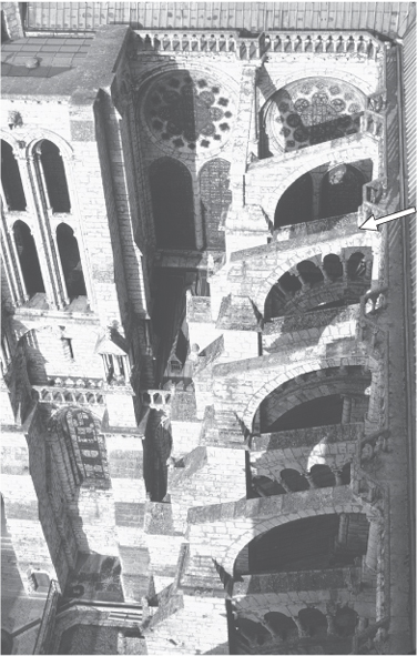
A continuous barrel vault over a space such as a hall, a wine cellar, or the nave of a church, is just a series of arches in a row, all pushing sideways uniformly and with solid supporting side walls resisting this push. However, if these side walls consist mostly of space (windows) then some other means of supporting the vertical load (the weight of the vault and the roof) and withstanding the sideways push has to be devised. So these forces have to be concentrated into individual columns between the windows. With everything being done to emphasize height, the columns supporting the vault to the nave of a church have to be slender. There is no difficulty in the columns carrying the vertical load from the vault and roof. Even in a cathedral like Chartres, near Paris, where the vault is 37 metres above the floor of the nave, the margin of safety appears to be large compared with the strength of the rock, which is of the order of a few kilometres. As we look up into the vault we can see the ribs channelling the loads into the columns. Unlike a bridge, there are no earth abutments at the top of the columns so a stone abutment-substitute has to be created. The horizontal push from the vault, and the loading from winds, can be absorbed by using elegant flying buttresses (Figure 7), which carry the load over the side aisles to lower external buttresses. Pinnacles on top of these buttresses push the load more effectively into the masonry.
6. Many arches are able to carry loads even when cracks open between rotated voussoirs, as in this bridge near Constantine (Algeria)
For most Gothic buildings the general scheme or concept would be defined by the dean and chapter of the cathedral but they, having no expertise in construction, would expect the master mason (engineer) with his team of masons and labourers to devise the structural (and decorative) detail and to work out how to build it. Such teams were peripatetic, moving from one construction site to the next as money ran out or became available. They would learn new ideas for the next project and there would, especially at a time of widespread church building as in the 13th century, be a lot of exchange of skills and quite a rapid transfer of knowledge over large distances. We can now rationalize the detail of the structure of Gothic buildings and use more or less sophisticated methods of calculation to conclude that the masonry is still fit for purpose. The masons could only build on experience transmitted as geometrical rules of proportion which defined increasingly daring but empirically safe structural forms: the unsafe ones are no longer there for us to see. Serendipitously, but perhaps not surprisingly, some of the modern analyses can also be reduced to geometrical constructions.
7. The arched vault of a Gothic cathedral such as Chartres requires support in the form of flying buttresses which carry the lateral loads (and wind load) over the aisles
Timber temporary structures enabled the masons to gain access to the working levels of the church and to provide support centring for the stone of the vaults and arches as they were being assembled. It would not have been practicable to erect scaffolding from the floor to the vault, and very difficult to arrange the safe removal of the centring to allow the vaults to take up their loads. Large churches are riddled with corner stairs and passages hidden in the larger columns and walls, giving access to temporary working platforms. The centring would have been strutted from projections and holes deliberately left in the walls below. Cranes (engines) driven by man-powered wheels (like large versions of hamster wheels, putting the energy to useful purpose) were used to lift blocks of stone.
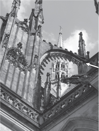
While the builders of the Gothic cathedrals were becoming ever more daring (Figure 8) with their exploration of the possibilities of the stone arch, the Khmer builders of the temples of Angkor in Cambodia (Figure 9) were still, in the 13th century after five or six centuries of building, sticking firmly to a trabeated form of construction using horizontal lintels and vertical supporting posts. They had not been told about the arch and could only bridge spaces with corbelled structures as used over the inner chambers within the pyramids several thousand years earlier.
8. The later Gothic flying buttresses at Prague reflect the increasing confidence and daring of the masons in their use of stone as a construction material
9. The temple builders in Angkor Thom, Cambodia, were still using corbelling to create archways in AD 1200
The knowledge possessed by the European masons (engineers) was kept within the group as far as possible: they had to train their successors but had also to give the impression that their largely empirical knowledge, based on geometrical rules whose prior success had been observed, was too complex for the layman, or amateur, or ecclesiastical client to grasp. Where failures occurred they were usually geometrical: extremely slender and tall columns became susceptible to instability through buckling if there was some slight change in alignment as a result of foundation settlement. The emergence of theoretical ideas which might support their designs (or might not) was regarded as a threat in somehow removing this aura of secrecy and skill and potentially opening their profession to anybody of mathematical education.
Iron has been used for several millennia for elements such as bars and chain links which might be used in conjunction with other structural materials, particularly stone. Stone is very strong when compressed, or pushed, but not so strong in tension: when it is pulled cracks may open up. The provision of iron links between adjacent stone blocks can help to provide some tensile strength. The concept was straightforward but the technology was challenging. The Industrial Revolution, in the 18th century, resulted in the development of techniques for the reliable production of iron (and later steel), which were then put to use in the creation of more exciting structures than could be produced with masonry alone.
Cast iron can be formed into many different shapes and is resistant to rust but is brittle – when it breaks it loses all its strength very suddenly. Wrought iron, a mixture of iron with a low proportion of carbon, is more ductile – it can be stretched without losing all its strength – and can be beaten or rolled (wrought) into simple shapes.
Steel is a mixture of iron with a higher proportion of carbon than wrought iron and with other elements (such as manganese or titanium or chromium) which provide particular mechanical benefits. Mild steel has a remarkable ductility – a tolerance of being stretched – which results from its chemical composition and which allows it to be rolled into sheets or extruded into chosen shapes without losing its strength and stiffness. There are limits on the ratio of the quantities of carbon and other elements to that of the iron itself in order to maintain these desirable properties for the mixture. Its development was thus associated with both the provision of close control of the chemical content in the blast furnaces (then the Bessemer converter, and latterly electric arc furnaces) and the construction of powerful rolling mills.
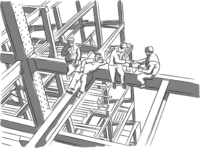
10. Site safety rules would today frown upon the antics of these workmen assembling the steel frame of a skyscraper in New York. However, the I cross-section of the beams and columns is apparent. The web carries the transverse load and the flanges resist bending – and improve resistance to buckling
There are many iconic photographs of the high-riggers on skyscrapers in New York, showing a disregard for safety precautions that would not be accepted today (Figure 10). If you look at a steel-framed building while it is being constructed you will see that most of the steel elements, vertical or horizontal, have an H section consisting of two parallel plates (flanges) connected by another plate (web). Steel is very strong and stiff in tension or pulling: steel wire and steel cables are obviously very well suited for hanging loads. If you push down on a long thin strip it will not remain straight but will buckle sideways, undergoing geometrical failure. If you are lucky, it will return to its original shape when you stop squashing it. This is the geometrical failure towards which the increasingly slender and tall stone columns of Gothic cathedrals were heading.
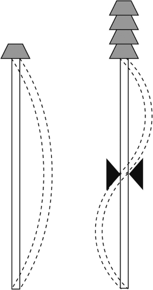
The buckling of a thin steel section might seem to indicate that the material has a low stiffness when it is compressed. This geometric loss of stiffness can be improved in two ways. If we hold the centre of the thin strip to stop it moving sideways and then push down we will find that the load at which the buckling instability occurs is about four times larger than for the unrestrained strip (Figure 11). The mode of buckling now has two bows, one each side of the central restraint. So, shortening the unsupported length is one way of improving the ability of a structural member to support compression.
The other way is to make it harder for the structural member to bow. A thin plate on its own has very little bending resistance. If the plate is incorporated into an H section then the bending becomes more difficult. However, even an H section steel girder will be much stronger when being pulled than when being compressed. In compression, buckling will eventually occur. The propensity to buckle thus depends on the cross-section of the girder and also on its length.
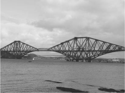
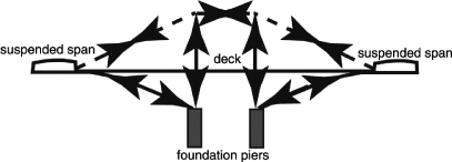
The design of the river crossing of the Firth of Forth (Figure 12), heading north from Edinburgh, was subjected to great scrutiny and conservatism of design because of the failure, in 1879, of the railway bridge across the River Tay – the next estuary to the north. The designer for the Forth Bridge Company, which was providing a vital link between sections of the railway network of the North British Railway Company, was Sir Benjamin Baker with Sir John Fowler. The result was the iconic structure, completed in 1890, somehow typifying Victorian engineering, and it is still in regular use for all railway traffic heading from Edinburgh to Dundee and Aberdeen. Such icons are not necessarily things of beauty but this one shows very well how it carries the loads (Figure 13), with strongly braced three-dimensional frames sitting over each pier separated by lighter structural sections which balance between the strong frames. It was the first major structure in Britain to be constructed entirely from steel (the contemporary Eiffel Tower in Paris was constructed of wrought iron). A similar structural arrangement was used for the Canadian National Railway bridge across the St Lawrence river, upstream of Quebec, completed in 1919.
11. (Left) A thin strip, loaded axially, develops a geometrical failure called buckling. (Right) If the strip is prevented from moving sideways at its midpoint then the load it can carry before it buckles is increased fourfold
12. The Forth Railway Bridge, near Edinburgh, was designed to resist much higher wind loading than the Tay bridge, some 50 km further north, which collapsed in a storm in 1879
13. The topmost members of the main truss of the Forth Railway Bridge (dotted) act in tension (pulling); the vertical and lower members of the truss (solid) act in compression (pushing). The truss is triangular in cross-section, giving extra stability. The suspended spans are, in comparison, very lightweight
Masonry (stone) arches have been recognized for more than two millennia as providing a strong way of bridging a gap in order to support loads of people or traffic. The arch converts the vertical forces provided by the steady or varying loads into horizontal forces at the abutments, each side of the gap. The abutments need to be sufficiently strong to be able to withstand this horizontal push. The shape of the arch has to be chosen to ensure that the masonry is in compression all round the arch. Masonry is heavy and may not be readily available locally. Steel provides a much lighter structural material. An arch can be formed out of a steel lattice with the cross-bracing ensuring that the unrestrained lengths of the compression elements are short enough to eliminate the possibility of buckling.
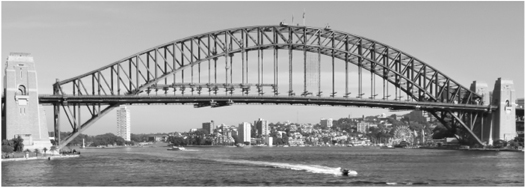
The Sydney Harbour Bridge (Figure 14), which was completed in 1932 with a main span of 503 m, is just such a steel arch bridge, but with the deck running through the arch at half height. It is very similar in appearance and structural form to the less well known Hell Gate Bridge in New York, a railway bridge 310 m long, designed by Gustav Lindenthal and completed in 1916. The deck is partly hung from and partly supported on (towards the ends of the main span) the steel arch which is terminated with a masonry tower at each end which serves the same structural purpose as a pinnacle over the outer wall of a Gothic cathedral, where it receives the force from a flying buttress. Its weight helps to push the resultant abutment force from the arch more directly downwards into the foundation. Aesthetically the towers give a reassuring sense of solidity to the bridge. The upper steel members, which also seem to form an arch, do not actually reach the masonry towers. They provide stiffening and lateral support to the arch itself in order to prevent it from buckling.
14. The deck of the Sydney Harbour Bridge is carried on a steel arch with plenty of vertical and diagonal bracing to ensure that the arch will not buckle
Concrete is a sort of artificial rock (conglomerate) which can be cast to almost any chosen shape and size. The Romans discovered that mixing pozzolana – a volcanic ash product found in the region around Vesuvius – with lime and water produced a reaction which, when complete, left a very strong rock-like material. The dome of the Pantheon in Rome was built in around AD 126 using this early concrete. A large quantity of massed concrete around the lower levels of the dome was used to absorb the horizontal thrusts. The Pantheon is intended to be admired from within (the coffered cut-outs from the underside of the dome help to reduce its weight) rather than from without. It remained the dome with the largest span in the world until the dome of Santa Maria del Fiore in Florence was completed.
For some applications, all that is required is the mass of the concrete, and its necessary mechanical properties are equivalent to those of an artificial rock. For example, with appropriate ground conditions, concrete gravity dams provide a straightforward means of blocking a valley and retaining a reservoir.
The Colorado River runs from the Rockies in Colorado and Wyoming through Utah, Arizona, and Nevada to the Mexican border and the Gulf of California. Its name comes from the colour of the sediments that it carries down to the sea. But for river water to reach the sea (in another country) seems a waste when it could be used to support growing city populations. The Hoover Dam (originally called the Boulder Dam, from the canyon that it closes) approved by Congress in 1928, together with the 400 km aqueduct to Los Angeles, was completed in 1935, providing a major source of construction employment during the Depression years. Congressional approval was notionally dependent on the completion of an agreement between at least six of the seven states which had an interest in the Colorado water. But the agreed water distribution was based on flow rates which were greatly overoptimistic. The dam retains a water depth of about 180 m and retains a reservoir which is some 180 km long with a volume of about 35 cubic kilometres. It regulates the flow in the downstream river to allow abstraction for the aqueduct but also relies on this flow through its turbines to generate 2.1 GW of electricity, of which a sizeable proportion is required to power the five pumping stations that take the water over the hills to the Californian coast.
A dam is just a big plug in a valley. This plug can be made in many different ways. Childhood experience of damming streams shows that compacted earth will restrict the flow and allow a (modest) lake to form. Including some stones or small rocks helps to give some extra solidity. But water is quite good at finding chinks – through or under or round the sides of the dam. Even if these holes are blocked, when the lake fills to the top of the dam the overflowing water will erode weaker elements of the downstream face. Few of those youthful constructions survive for long.
The same problems face the designer of a real dam. Initially, small dams across the valley divert the river into pipes or tunnels so that the subsequent serious construction work can proceed in the dry. At the Hoover Dam parts of these diversion tunnels were incorporated into the eventual spillway system allowing controlled flow of water into the downstream river and also a safe means of discharge, without erosion of the dam, when the reservoir is full.
The pressure exerted by 180 m of water is high and has somehow to be transmitted to the base and sides of the gorge in which the dam is to be built. An arch is an effective way of transmitting vertical loads from bridge traffic to the horizontally resistant abutments. An arch dam performs the same mechanical process but turned through 90 degrees. The Hoover Dam is a combined gravity arch concrete dam. The convex arched upstream section in plan takes the water pressure to the sides of the gorge. The descriptor gravity refers to the sheer bulk of the dam sitting on the floor of the gorge and resisting downstream movement. The dam is 200 m thick at its base and 14 m thick at the crest, which is 380 m long, and it has a volume of 2.5 million cubic metres.
As concrete sets, the chemical reactions that turn a sloppy mixture of cement and water and stones into a rock-like solid produce a lot of heat. If a large volume of concrete is poured without any special precautions then, as it cools down, having solidified, it will shrink and crack. The Hoover Dam was built as a series of separate concrete columns of limited dimension through which pipes carrying cooling water were passed in order to control the temperature rise. Evidently the junctions between the blocks needed to be sealed and the cooling pipes to be filled, and the rock beneath and beside the dam to be rendered impermeable.
Grout is a fine mixture of cement, water, and sand which can be pumped into gaps and fissures. Holes drilled in the valley floor were used to inject a grout curtain in order to seal the rock to a depth sufficient to limit any leakage from the full reservoir. Similarly, having understood the nature of the geological structures present in the sides of the valley, these rocks were grouted both to prevent flow of water and also to strengthen them to resist the abutment forces from the dam.
The importance of understanding the geology of a site for the construction of a dam was emphasized by the failure in 1959 of the Malpasset Dam in south-east France. This was a double curvature mass concrete arch dam – curved both horizontally (like Hoover) but also vertically. It was the thinnest arch dam ever built – 7 m thick at the base and 1.5 m thick at the crest – and about 60 m high and 190 m between abutments. Completion in 1954 was followed by a series of dry years (and a problem with a recalcitrant landowner) and it was not until the extremely heavy rains in late 1959 that the reservoir filled very rapidly. The dam failed on the evening of 2 December killing 423 people downstream. Protracted investigations revealed weak seams in the rock of the left abutment which had displaced slightly under the rapidly rising water load. This displacement was enough to destroy the elegant structure.
Concrete is mixed as a heavy fluid with no strength until it starts to set. Embedding bars of a material such as steel, which is strong in tension, in the fluid concrete gives some tensile strength. Reinforced concrete is used today for huge amounts of construction throughout the world. When the amount of steel present in the concrete is substantial, additives are used to encourage the fresh concrete to flow through intricate spaces and form a good bond with the steel.
For the steel to start to resist tensile loads it has to stretch a little; if the concrete around the steel also stretches it may crack. The concrete has little reliable tensile strength and is intended to protect the steel. The concrete can be used more efficiently if the steel reinforcement, in the form of cables or rods, is tensioned, either before the concrete has set or after the concrete has set but before it starts to carry its eventual live loads. The concrete is forced into compression by the stretched steel. The working loads that the concrete has to support would have been expected to generate tension in the concrete. As a result of the prestressing, these loads are carried by reducing this initial compression of the concrete.
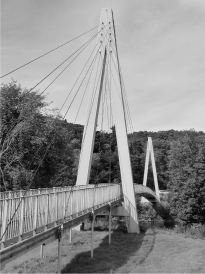
Such prestressed concrete gives amazing possibilities for very slender and daring structures (Figure 15). The analysis of such structures provides its own challenges: the concrete must be able to withstand the tension in the steel, whether or not the full working loads are being applied. For an arch bridge made from prestressed concrete, the prestress from the steel cables tries to lift up the concrete and reduce the span whereas the traffic loads on the bridge are trying to push it down and increase the span. The location and amount of the prestress has to be chosen to provide the optimum use of the available strength under all possible load combinations. The pressure vessels used to contain the central reactor of a nuclear power station provide a typical example of the application of prestressed concrete.
15. Prestressed concrete provides possibilities for extremely slender structures such as this ribbon footbridge at Shirakawa in Japan
All nuclear power generation so far relies on the principle of nuclear fission: when bombarded with neutrons, uranium 235 decays into other elements (such as krypton and barium) with the release of several neutrons. These neutrons are available to bombard other uranium atoms to encourage further degradation, each time with the release of energy. At the centre of a nuclear power station is a reactor in which this process occurs in a controlled fashion. Control is provided by a combination of nuclear moderator and control rods made of material which is ‘poisonous’ to neutrons and thus can absorb them or slow them down so that their thermal energy can be extracted. Graphite is a good moderator, and the cores of nuclear reactors are often formed of carefully engineered graphite blocks. The coolant fluid used to extract heat from the core can also have moderating properties.
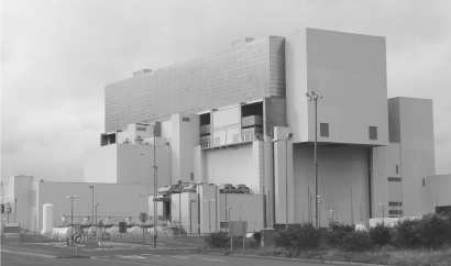
The nuclear power station at Torness in south-east Scotland (Figure 16), using advanced gas-cooled reactors, was among the last of this type to be built in the UK at the end of a programme of nuclear investment which began in the 1950s. It has a generating capacity of 1.36 GW and came on power in 1988 after an 8 year construction period. Its operating life is presently destined to end in 2023. The two reactors use carbon dioxide at 40 times atmospheric pressure as the coolant of the radioactive core. Water is pumped through a heat exchanger in the reactor where it absorbs heat from the circulating carbon dioxide and is turned to steam at a temperature similar to that used in typical coal-fired power stations. The steam expands through the turbines and in generating power loses pressure and partially condenses to water. The condensation process is completed in a cooling loop, and the resulting liquid is ready to start the cycle once more. The condensation process requires cooling water, and typically power stations are located by a convenient river or other source of water – Torness is on the coast.
There are many civil engineering contributions required in the several elements of the power station – and certainly many interactions with specialists from other branches of engineering. The electricity generation side of a nuclear power station is subject to exactly the same design constraints as any other power station. Pipework leading the steam and water through the plant has to be able to cope with severe temperature variations, rotating machinery requires foundations which not only have to be precisely aligned but also have to be able to tolerate the high frequency vibrations arising from the rotations. Residual small out-of-balance forces, transmitted to the foundation continuously over long periods, could degrade the stiffness of the ground. Every system has its resonant frequency at which applied cyclic loads will tend to be amplified, possibly uncontrollably, unless prevented by the damping properties of the foundation materials. Even if the rotating machinery is being operated well away from any resonant frequency under normal conditions, there will be start-up periods in which the frequency sweeps up from stationery, zero frequency, and so an undesirable resonance may be triggered on the way – just as there is often a slightly alarming stage as a washing machine moves into the spin stage.
16. The grey cuboids of the power station at Torness, Scotland, give no clue of the prestressed concrete nuclear reactors and power generation plant to be found inside
The coolant under high pressure in the nuclear reactor has to be retained in a pressure vessel: complete integrity of the containment vessel is important. Torness has a central gas-tight liner formed of 13 mm thick carbon steel and around this a prestressed concrete pressure vessel 5.5 m thick which acts as a biological shield. A vessel under internal pressure is trying to pull itself apart in all directions. The concrete in the pressure vessel must be kept under compression by embedding a dense array of steel wires which are pretensioned before the internal pressure is applied. The stretching of the wires is equilibrated by compression of the concrete. All the internal pressure now does is to reduce this compression.
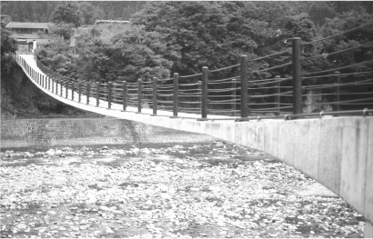
The use of plastic or composite materials (other than reinforced concrete) in conventional civil engineering structures has not developed very rapidly. Such plastic composites tend to be more expensive than their metallic equivalents so, unless weight is of particular concern (as in aircraft structures), there is no natural economic driver for their use. Carbon fibre sheets have been used to repair or strengthen existing structures to improve their resistance to earthquakes, where their light weight makes them easier to handle and position. Construction companies having been found to be reluctant to blaze a trail in the use of an unfamiliar material, the all-plastic footbridge at Aberfeldy, Scotland (Figure 17) was erected by students (without any need for high capacity lifting ‘engines’).
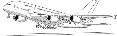
To link the Airbus A380 (Figure 18) and civil engineering may seem fanciful. However, an aircraft is a large structure, and the structural design is subject to the same laws of equilibrium and material behaviour as any structure which is destined never to leave the ground. The aerodynamic loads on the wings are of course an essential part of the loading for an aircraft; for most land-based structures the wind loading will be a lesser component of loading. The A380 is an enormous structure, some 25 m high, 73 m long and with a wingspan of about 80 m; the area of the wings is about 850 m2; and the aircraft can carry some 853 passengers, on two floors, if fitted out only for economy class. For comparison, St Paul’s Cathedral in London is 73 m wide at the transept; and the top of the inner dome, visible from inside the cathedral, is about 65 m above the floor of the nave.
17. Civil engineering contractors have hesitated to tackle new construction materials. The footbridge at Aberfeldy was built entirely from plastic by Dundee University students under the direction of Bill Harvey
18. Any aeroplane is subject to the same laws of structural mechanics as conventional ground-based structures. The Airbus A380 has dimensions which are similar to those of a large building. Use of plastics in aircraft structures provides strength with reduced weight
The structure of the A380 makes much use of plastic – composite – materials in its quest for lighter, stronger structures. Such composite materials obtain their desirable strength and stiffness properties from fibres of glass or carbon which are carefully aligned – exactly like the steel in reinforced concrete – in such a way as to best resist the stresses developed by the loadings applied to the structure – especially those applied to the wings. These strong fibres are protected by a weaker and less stiff matrix. The resulting materials are lighter than most metallic materials of the same or greater stiffness and strength.
But the Airbus A380 is also a wonderful example of the elaborate management and organization required for any complex engineering project. The aircraft are ultimately fitted out in Hamburg having been previously assembled in Toulouse. The rear sections of the fuselage come from Hamburg; the wings are manufactured in the UK; some of the front sections of the fuselage are manufactured in St Nazaire, France; the belly and tail of the plane come from Cadiz in southern Spain. These enormous parts are transported from their various origins by sea to Bordeaux on the Atlantic coast of France and then to Toulouse first by canal and then in a road convoy along carefully chosen routes, avoiding tight corners and narrow carriageways but ensuring adequate strength of the road surface. The Airbus A380 is thus typical of many modern projects in its need for the successful integration of a wide range of engineering skills and disciplines.
‘Before the Roman came to Rye or out to Severn strode, the rolling English drunkard made the rolling English road.’ But after the Romans had left, the English reverted, and created lanes and roads that wound round the natural features of the landscape, skirted fields, linked farms with mills and with market towns – straight lines were the coincidental exception rather than the norm. The Romans had very clear notions concerning road layout – there was a wide paved carriageway with clear areas each side of the carriageway to remove the possibility of cover for ambush. These roads were clearly provided for military purposes. The concept of formal road building also disappeared with the departure of the Romans. The hope was that human and animal feet and cart wheels would compact the ground sufficiently to give a modest stability. But come the rains, and the track would once again become a mire. The farmer taking produce to and from market with a beast of burden could pick his way across the terrain, but armies with their chariots and military equipment (engines) needed something more serious to aid their rapid deployment. (One might imagine that elephants could be used to compact a layer of soil being placed for a road. Unfortunately, an elephant having once traversed a certain route will remember where it has been and always place its feet in the same spots: pachydermic compaction of an area of soil is not effective.)
Road design makes use of designer soils: materials from the ground are modified in order to give particular mechanical properties. There are also special materials that are used for construction of the road pavement (the surface on which the traffic runs). The principles of design of roads have not changed much over two millennia, even if the loading provided by the juggernaut lorries of today considerably exceeds that provided by Roman chariots and soldiers. The materials available for pavement construction have been improved, and the machinery available for placing and compacting those materials has developed – particularly in scale. The Via Appia which leads from Rome to Brindisi on the Adriatic coast, a distance of 360 Roman miles (about 530 km), built over a period of about 60 years around 300 BC, still exists. Traffic requires a strong running surface, resistant to wear. This layer needs some underlying support to prevent it spreading, and an underlying drainage layer to draw rainwater into lateral ditches to prevent the formation of a morass in wet weather. The Via Appia had a running surface some 4.1 m wide (to permit two-way military traffic) formed of shaped tightly fitting smooth stone slabs laid on a layer of gravel to provide the drainage: a labour intensive operation for which the availability of slave labour is helpful.
Adaptations were needed if the road had to cross swampy ground. The Romans developed a technique using osiers – willow branches – spread across the soft ground both to help distribute the load and also to tie together the road base material in order to discourage it from flowing out sideways. Today road designers use synthetic reinforcing materials – so-called geogrids or geomembranes – to achieve the same result.
When the features of good road construction were rediscovered in the 18th century by, among others, Thomas Telford (1757–1834) in Britain, efforts were concentrated on finding ways of producing a tightly packed running surface. John McAdam (1756–1836) became obsessed with the size of stones to be used. He specified a maximum size of 20 mm for the stones: a road-building labourer could check whether a rock had been adequately broken by seeing whether the resulting stones could be fitted into his mouth. This size was chosen to be significantly smaller than the typical wheel rim thickness (100 mm). McAdam reckoned that the severity of Telford’s camber was not necessary to guarantee sufficient runoff of rainwater, so his designs were more economical.
The material which we see so often on modern road surfaces, and known as tarmac(adam) or asphalt, preserving his name at least in part, was introduced in the early 20th century. Binding together the surface layers of stones with bitumen or tar gave the running surface a better strength. Tar is a viscous material which deforms with time under load; ruts may form, particularly in hot weather. Special treatments can be used for the asphalt to reduce the surface noise made by tyres; porous asphalt can encourage drainage. On the other hand, a running surface that is more resistant to traffic loading can be provided with a concrete slab reinforced with a crisscross steel mesh to maintain its integrity between deliberately inserted construction joints, so that any cracking resulting from seasonal thermal contraction occurs at locations chosen by the engineer rather than randomly across the concrete slab. The initial costs of concrete road surfaces are higher than the asphalt alternatives but the full-life costs may be lower. The eventual process of replacement of a concrete road surface may be more complex and disruptive to traffic flow than the repair of an asphalt surface and the driving experience, registering each construction joint in turn, may be less comfortable: there are various factors which might influence the choice.
While an aeroplane is not strictly a product of civil engineering, much of the infrastructure of an airport certainly is. There are buildings of greater or lesser complexity and architectural pretension, there are transport connections both between parts of the airport and between the airport and the outside world, and there are the runways. A runway pavement provides a foundation for a structure (the aeroplane) which can be placed anywhere within its area and which will generate dynamic impact loading as well. A runway is essentially just a short road and is subject to the same design considerations. Just as for heavy lorries, the load of an aeroplane is spread over a number of tyres in order to keep the individual loads to a satisfactory minimum. The runway spreads the load from these tyres into the underlying ground without significant deformation, temporary or permanent, of the runway surface. As with roads, runways may be surfaced with asphaltic or concrete materials. In choosing a material the likely need for, and frequency of, maintenance and repair will be particularly important since closure of a runway for more than a night-time slot will have major repercussions for the operation of the airport.
In many cases the engineer will need to make a choice between different candidate materials. There may be some uncostable influences on this choice – for example, aesthetic considerations – but it is likely that the choice will ultimately be governed by economic constraints. Choice of material should take account of the real costs involved. Different candidate materials will have different initial costs and different lifetimes: perhaps the cheaper material will need to be replaced much sooner. Conscientious full-life costing of civil engineering projects is important at a time when we are particularly concerned to make our activity on Earth more sustainable. The full costing should consider the energy requirements for the manufacture and transport of the materials that are being used (which may not be fully reflected in market prices) and also the costs of demolition and disposal or reuse of the construction materials. Many buildings are being constructed with an anticipated life of 25–50 years (compare the value for money of the longevity of the mediaeval cathedrals) – perhaps because it is expected that technological developments within that period will render current engineering solutions inappropriate.