Chapter 17
Processing
17.1 Introduction
In earlier chapters, we have discovered how to synthesize and characterize polymers. But how do we get the preponderance of polymeric products commonly manufactured? Here, we discuss polymer processing, which describes the technology used to convert raw polymer, or compounds containing raw polymer, to articles of a desired shape and size. Considering the wide variety of polymer types and the even wider variety of articles made from them, a complete description and analysis of the myriad of processing techniques that have sprung up through the years would be impossible here. There are references that provide detailed qualitative descriptions of polymer-processing operations [1–4] and many websites that provide photographs or videos of these operations. Similarly, quantitative treatment of processing operations has been the subject of a number of books [5–10]. Here, we outline some of the common processing techniques (Table 17.1), introduce termi-nology, and consider how the various techniques are based on fundamentals previously discussed. The reader wishing additional detail may consult these references and the more specialized ones cited in the sections to follow.
Table 17.1 Polymer Processing Techniques.
| Processing Technique | Brief Description | Example Products |
| Injection molding (Section 17.2) | Molten polymer injected into metal mold; solidifies by cooling | Lawn furniture, garbage cans |
| Foam molding (Section 17.2) | Molten polymer with volatile blowing agent that expands the polymer as it evaporates or degrades, producing a gas | Styrofoam® coffee cups, polyurethane seat cushions |
| Reaction injection molding (Section 17.2) | Starting prepolymers (usually condensation-type) are injected into a heated mold, where they react | Energy-absorbing front or rear car bumpers |
| Extrusion (Section 17.3) | Molten polymer is extruded through an opening with a cross-sectional shape matching the desired product | Hoses, tubing, vinyl house siding, wire coatings |
| Blow extrusion (Section 17.3) | Forms very thin sheets by expanding extruded cylindrical sheets with pressurized air before rolling | Plastic wrap |
| Blow molding (either injection or extrusion) (Section 17.4) | A parison of molten polymer is formed inside a mold, then filled with air to form the hollow insides | Soda bottles, detergent bottles |
| Rotational molding (fluidized bed or slush) (Section 17.5) | Powdered polymer is put in a heated mold that is rotated to melt the polymer into the desired shape | Irregular hollow objects, toys |
| Calendering (Section 17.6) | Polymer sheets are pulled and stretched between heated metal rolls (produces larger than 0.01 in. thick) | Shower curtains, vinyl upholstery, vinyl floor tile |
| Thermoforming (Section 17.7) | A polymer sheet is heated and forced into a cooled mold; vacuum can be used | Drinking cups, meat trays, boat hulls, corrugated sheeting |
| Stamping (Section 17.8) | Heated thin thermoplastic sheets stamped into a mold | Bucket seat bottoms, battery trays (in cars) |
| Solution casting (Section 17.9) | Polymer dissolved in solvent which evaporates leaving a thin film | Photographic film |
| Casting and crosslinking (Section 17.10) | Monomers or pre-polymers are cast into a mold and set by a crosslinking reaction | Electrical coatings, reproduction of carved objects |
| Reinforced thermoset molding (Section 17.11) | Fiberglass-reinforced plastics made by successive layers of fibers and polymer resin, which is crosslinked | Automotive body panels, bathtubs, golf clubs |
| Fiber spinning (Section 17.12) | Polymer extruded in thin fibers through a spinnerette and solidified by cooling, drying, or solvent exchange | Fibers for most kinds of clothing; stretchy spandex, acrylic yarns |
| Compounding (Section 17.13) | Intensive mixing, similar to kneading dough, used to mix additives in polymers | Automotive tires; composites |
| Lithography (photo-) (Section 17.14) | A mask is used to shield light from a pre-polymer solution; forms highly-complex products with small features | Electronic materials such as integrated circuits |
| 3-D printing (Section 17.15) | Adding polymer layer-by-layer using computer-aided design to form complex geometries | Architectural prototypes, medical (tissue scaffolds, teeth) |
17.2 Molding
Molding consists of confining a material in the fluid state in a mold where it solidifies, taking the shape of the mold cavity. Injection molding [11, 12] is the most common means of fabricating thermoplastic articles. Figure 17.1 illustrates a typical injection press. The molding compound, usually in the form of pellets of approximately 1/8-in. (3-mm) cubes or 1/8-in.-long cylinders (molding “powder”) is fed from a hopper (which may be heated with circulating hot air to dry the material) to an electrically heated barrel. The pellets are conveyed forward through the barrel by a rotating screw. The material is melted as it goes by a combination of heat from the barrel and the shearing (viscous energy dissipation) of the screw.
Figure 17.1 Injection molding machine. From Modern Plastics Encyclopedia, McGraw-Hill, New York, 1969–1970 ed.

Older machines had a reciprocating plunger in place of the screw. All the heat for melting had to be supplied by conduction from the barrel, and mixing was very poor. This resulted in low plasticizing (melting) rates, and a thermally nonuniform melt. The screw generates heat within the material and provides some mixing, thereby increasing plasticizing rates and giving a more uniform melt temperature.
Molten material passes through a check valve at the front of the screw, and as it is deposited ahead of the screw, it pushes the screw backward while material from the previous shot is cooling in the mold. The cooled parts are ejected from the mold, the mold closes, and the screw is pushed forward hydraulically, injecting a new shot of molten plastic into the mold.
Some machines have a two-stage injection unit. A rotating-screw preplasticizer feeds molten polymer into an injection cylinder, from which it is injected into the mold by a hydraulically driven plunger. This configuration is claimed to provide better control of shot size.
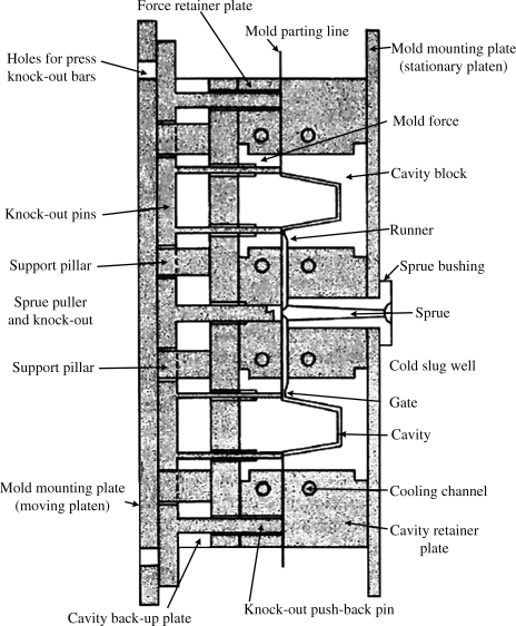
The molten polymer flows through a nozzle into the water-cooled mold, where it travels in turn through a sprue, runners, and a narrow gate into the cavity (Figure 17.2). When the part has cooled sufficiently, the mold opens and knockout pins eject the parts, with material cooled in the sprues and runners attached. This material is removed by hand or by robots (or left intact in the case of many toy model kits). With thermoplastics, this material is chopped and recycled back to the hopper as regrind. Depending on the extent of material degradation in the cycle and the property requirements of the finished part, injection-molding operations may tolerate up to 25% regrind in the hopper feed. Hot-runner molds contain heaters that maintain the material in the sprue and runners in the molten state, and often a shutoff valve (“valve gate”) at the gate. This eliminates the need for regrind.
Figure 17.2 Two-cavity injection mold. From Modern Plastics Encyclopedia, McGraw-Hill, New York, 1969–1970 ed.
The molds are opened and closed by hydraulic cylinders, toggle mechanisms, or combinations of both. These have to be pretty hefty because pressures in the mold can reach several thousand psi and the projected surface area of some parts may be hundreds of square inches.
The molds themselves often involve much intricate hand labor and can be quite mechanically complex. Surfaces are usually chrome-plated for wear resistance. Molds can thus be quite expensive, but when amortized over a production run of many thousand parts, the contribution of mold cost to the cost of the finished item may be insignificant.
Injection-molding presses are rated in terms of tons of mold-clamping capacity and in ounces (of general-purpose polystyrene) of shot size. They range from 2-ton, 0.25-oz laboratory units to 6600-ton, 2400-oz monsters that are used to mold garbage cans, TV cabinets, dishwasher tubs, lawn furniture, etc. They are usually completely automated. Cycle times (and therefore production rates) sometimes depend on plasticizing capacity (the rate at which the material can be melted), but more often than not are limited by the cooling time in the mold, which, in turn, is established by the thickness of the part and the (usually very low) thermal diffusivity of the material. Typical cycle times are between 1/4 and 2 min. As usual, there are compromises involved. It is often tempting to try to reduce cooling time by lowering the mold temperature, and thereby increasing the cooling rate, and/or lowering the temperature at which the material is injected into the mold, reducing the amount it must be cooled before solidifying enough to allow removal from the mold without distortion. The higher material viscosity that results, however, can give rise to short shots (incomplete mold filling), poor surface finish, and part distortion from frozen-in strains (see below).
Injection-molding machines now are commonly equipped with feedback control systems that monitor cavity pressure, screw position, and/or screw velocity and control these variables through the hydraulic system to provide high-quality, uniform parts, using a minimum amount of material and minimizing the number of rejects.
Foamed plastic articles are molded by incorporating a blowing agent (Chapter 7). These blowing agents may be inert but volatile liquids, compounds that decompose chemically at elevated temperatures to liberate a gas such as nitrogen or carbon dioxide, or simply nitrogen dissolved in the polymer. In any case, the blowing gas is kept in solution by the high pressures ahead of the screw. The mold is partially filled with a shot from the cylinder. The reduced pressure within the mold allows the blowing agent to vaporize, expanding the shot to fill the cavity and giving a foamed part.
One drawback of traditional injection molding was its inability to produce parts with complex internal passages. To be sure, simple holes could be incorporated by using core pins that are retracted mechanically either parallel or perpendicular to the mold-opening direction. To permit retraction, however, these pins (and the resulting holes) had to be straight and if not of constant cross section, tapered appropriately with regard to the direction of retraction.
The lost-core process allows the molding of parts with curved internal passages of varying cross section. The core is cast in a low melting bismuth–tin alloy. This cast core is placed in the injection mold and the plastic is molded around it. After the part is ejected from the mold, the metal core is melted out. The high thermal diffusivity of the metal core prevents its melting during the molding step. This process can be used for automotive intake manifolds, where it provides the necessary curved passages with a nice, smooth interior finish.
Injection molding was at one time confined exclusively to thermoplastics. It is now also used for thermosets, which are injected into a heated mold, where they solidify through a curing (crosslinking) reaction. This is a tricky operation. The compound must be heated just enough in the barrel to achieve fluidity and injected into the mold before it begins to cure appreciably, otherwise the entire machinery becomes a sticky mess. This requires precise control of temperatures and cycle timing to prevent premature cure in the barrel and the resulting shutdown-and-cleanout operation. Thermoset sprues and runners cannot be recycled, of course, and must be minimized to cut waste.
Thermosetting compounds are traditionally compression molded. The molds are mounted in hydraulic presses on steam-, electric-, or oil-heated platens. The molding compound is fed to the heated mold, which closes, maintaining the material under pressure until cured. The part is then ejected from the mold.
Molding compound in the form of granules or powder may be fed to the mold automatically in weighed shots, or as pre-formed (by cold pressing) tablets. The charge is often preheated to reduce heating time in the mold and thereby cycle time.
Mold temperature is a critical variable in compression molding. The higher it is, the faster the material cures, but if it cures too fast, it will not have enough time to fill thin sections and far corners of the mold, so a compromise must be reached. Material suppliers attempt to optimize the cure characteristics to provide minimum cycle times.
Transfer molding is a variation of compression molding. Here, the material is melted in a separate transfer pot, from which it is squirted into the mold. This can give faster cycle times and since no solid material is pushed around in the mold cavity itself, damage to delicate inserts (e.g., metal electrical contacts molded into a part) is minimized, mold wear is reduced, and greater ease in filling intricate molds and more uniform cures are obtained. However material cured in the transfer pot and sprue is wasted.
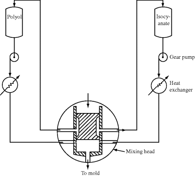
Reaction injection molding (RIM) [13] (Figure 17.3) is a process developed to mold large polyurethane (Example 2.4Q) or polyurea (Example 2.4) materials directly from the starting chemicals with cycle times comparable to injection molding. Between shots, the highly reactive liquid polyol (for polyurethanes) or polyamine (for polyureas) and isocyanate components are circulated from separate tanks through heat exchangers that regulate their temperatures. During the shot, the streams are pumped at about 2500 psi through nozzles in a mixing head, where they are impinged at high velocity and thoroughly mixed by the resulting turbulence. The mixed stream begins to react as it flows into the mold, where the polymerization reaction is completed. The mold is maintained at about 150 °F, initially heating the reacting system but later removing the exothermic heat of polymerization as the temperature rises while the reaction approaches completion. Since the unreacted system is relatively low in viscosity (about like pancake syrup), unlike the molten polymer in an injection-molding process, it flows easily to fill large molds with narrow clearances at relatively low pressures (100 psi, or so, in contrast to the thousands of psi in injection molding). These low pressures allow the use of relatively inexpensive molds and low-force mold clamping systems (compared to injection molding).
Figure 17.3 RIM. The Kraus–Maffei mixing head is shown in the shot position. At the end of the shot, the plunger moves down, packing the mold, cleaning the mixing chamber, and recirculating the reactant streams back to their storage tanks.
The polyurethanes and polyureas may be formulated to be flexible or rigid, solid or foamed. Fillers and/or reinforcing agents (e.g., glass fibers or flake) may be added to one or both components (in which case the process is sometimes known as RRIM-reinforced RIM). A major application of RIM is to produce energy-absorbing front and rear ends and body panels for automobiles. Cycle times of 2 min or less are feasible for such large parts.
RIM has achieved considerable success, particularly in the automotive industry, where the drive to cut vehicle weight is intense. RIM panels have replaced stamped steel in a variety of automotive applications. However, RIM faces stiff competition from other plastics and processes, injection-molded thermoplastics, for example, for this large market.
A somewhat similar process known as resin-transfer molding (RTM) is used to produce highly reinforced parts from low-viscosity, reactive starting materials. Reinforcing preforms, usually consisting of layers of fiberglass cloth or mat, are placed in the mold. When the mold is closed, they pretty much extend throughout the cavity and therefore the finished part. The resin and catalyst components are forced by positive-displacement piston pumps through a static or motionless mixer (see Figure 17.12) into the closed mold, where they cure. To ensure rapid and complete impregnation of the reinforcing material, care must be taken to vent the mold properly to allow the escape of air as the resin is injected. In some cases, the air is sucked out of the mold with a vacuum pump prior to resin injection.
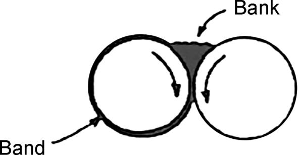
Figure 17.12 Two-roll mill.
RTM has been mainly used with unsaturated polyesters (Example 2.3), but it is also applicable to epoxies, polyurethanes, etc. Parts weighing hundreds of pounds have been produced (e.g., truck air deflectors). As with RIM, because the viscosity of the flowing material is low, relatively modest pressures and inexpensive molds are required.
Some newer methods of forming complex three-dimensional shapes combine computer-aided three-dimensional design with printing technology that build an object by adding polymer pellets and growing a shape. This has been done to make replicas of fragile artifacts, develop medical implants with precise geometries, and construct complex three-dimensional scaffolds for seeding cells for tissue engineering. Alternatively, shapes can also be carved from a polymer block (see Section 17.14 on lithography), similar to sculpting, but the size of any interior cavities is dependent on the size of the tool used in carving.
17.3 Extrusion [14–17]
Thermoplastic items with a uniform cross section are formed by extrusion. This includes many familiar items such as pipe, hose and tubing, gaskets, wire and cable insulation, sheeting, window-frame moldings, and vinyl siding for houses. Molding powder is conveyed down an electrically or oil-heated barrel by a rotating screw. It melts as it proceeds down the barrel and is forced through a die that gives it its final shape (Figure 17.4). Vented extruders incorporate a section in which a vacuum is applied to the melt to remove volatiles such as traces of unreacted monomer, moisture, solvent from the polymerization process, or degradation products.
Figure 17.4 Vented extruder. From Modern Plastics Encyclopedia, McGraw-Hill, New York, 1969–1970 ed.
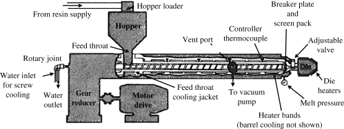
The design of extruder screws is an interesting and complex technical problem and has received considerable study. Screws are optimized for the particular polymer being extruded. Basically, a screw consists of three sections: melting, compression, and metering. The function of the melting section is to convey the solid pellets forward from the hopper and convert them into molten polymer. Its analysis involves a combination of fluid and solid mechanics and heat transfer. The compression section, in which the depth of the screw flight decreases, is designed to compact and mix the molten polymer to provide a more-or-less homogeneous melt to the metering section, where the molten polymer is pumped out through the die.
This last section is well understood. Analysis of the metering section is an interesting application of the rheological principles discussed previously (Chapter 14), as is much of die design. The determination of the die cross section needed to produce a desired product cross section (other than circular) is still pretty much a trial-and-error process, however. Viscoelastic polymer melts swell upon emerging from the die (i.e., die swell, which is caused by the recovered stored elastic energy after squeezing through the die) and the degree of die swell cannot be reliably predicted.
In addition to die swell, as the extrusion rate is increased, the extrudate begins to exhibit roughness, and then an irregular, severely distorted profile. This phenomenon is known as melt fracture. It is generally attributed to melt elasticity, but there is currently no way of quantitatively predicting its onset or severity. It can be minimized by increasing die length, smoothly tapering the entrance to the die, and raising the die temperature.
Extruders are normally specified by screw diameter and length-to-diameter ratio. Diameters range from 1 in (2.5 cm) in laboratory or small production machines to 1 ft (30 cm) for machines used in the final pelletizing step of production operations. Typical L/D ratios seem to grow each year or so, with values in the 20/1 to 36/1 range.
Single-screw extruders pump the polymer based on the drag flow of material between the rotating screw and the stationary barrel. As a result, they are not positive-displacement pumps and tend to give a rather broad residence time distribution. Moreover, they are not particularly good mixing devices. Counter-rotating twin-screw extruders are true positive-displacement pumps, capable of generating the high pressures needed in certain profile extrusion applications. Co-rotating twin-screw extruders, though not positive displacement pumps, can give excellent mixing and a narrow residence time distribution with proper screw design (subjecting all the material to essentially the same shear and temperature history). They are, therefore, used extensively in polymer compounding (mixing) operations and, to a certain extent, as continuous polymerization reactors.
In steady-state extruder operations, most or all of the energy needed to plasticize the polymer is supplied by the drive motor through viscous energy dissipation. The heaters on extruders are needed mainly for startup and because enough heat cannot always get from where it is generated (the compression and metering zones) to where it is needed (the melting zone). In fact, cooling through the barrel walls and/or screw center is sometimes necessary. A steady-state energy balance on a typical operating extruder is shown below [17]:
| Extruder: | 3.5-in (8.9-cm) barrel 32/1 L/D |
| Material: | high-impact polystyrene |
| Operating Conditions: | screw speed 121 rpm throughput 566 lb/h (257 kg/h) |
| Energy Inputs | |
| Shaft work (viscous energy dissipation) | +90 % |
| Heaters | +10% |
| Energy Outputs | |
| Polymer enthalpy increase | −65% |
| Losses to ambient | −15% |
| Cooling water | −10% |
The complex interplay between the rate of viscous energy dissipation, temperature, and material viscosity in an extruder sometimes results in a variation in output (surging) even at constant screw speed. Where it is necessary to minimize surging, positive-displacement gear pumps are often added after the extruder.
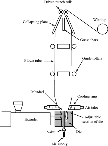
Most packaging film, such as Saran® wrap, is produced by blow extrusion (Figure 17.5). A thin-walled, hollow cylinder is extruded vertically upward. Air is introduced to the interior of the cylinder, expanding it to a tube of film (less than 0.01 in thickness). The tube is grasped between rolls at the top, preventing the escape of air and flattening it for subsequent slitting and windup on rolls. The expanded tube is rapidly chilled by a blast of air from a chill ring as it proceeds upward. With crystalline polymers such as polyethylene and polypropylene, this rapid chilling produces smaller crystallites and enhances film clarity.
Figure 17.5 Blow extrusion film line. From Modern Plastics Encyclopedia, McGraw-Hill, New York, 1969–1970 ed.
“Cast” film is produced by extruding the polymer from a slot die onto polished metal chill rolls. The rolls maintain a more uniform thickness (gage) and the more rapid cooling and smoother surface finish provide superior film clarity. On the other hand, cast film is oriented (stretched) only in the machine direction, whereas blown film is biaxially oriented, and therefore has superior mechanical properties in equivalent thickness (or equivalent properties in a thinner film).
17.4 Blow Molding [18]
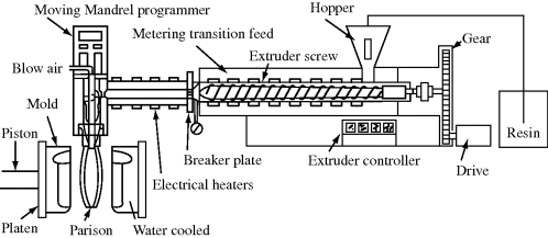
A quick walk through a supermarket provides convincing proof of the economic importance of plastic bottles. They are nearly all made by blow molding. In one form of this process, extrusion blow molding (Figure 17.6), a hollow cylindrical tube or parison is extruded downward. The parison is then clamped between halves of a water-cooled mold. The mold pinches off the bottom of the parison and forms the threads on the neck of the bottle. Compressed air expands the parison against the inner mold surfaces, and when the part has cooled sufficiently, the mold opens and the part is ejected. In one form of machine, the mold “shuttles” aside for blowing and ejection as a new parison is being formed beneath the die. High-production rotary machines may have two parison heads and index as many as 20 molds past them on a rotating table.
Figure 17.6 Extrusion blow molding. From Modern Plastics Encyclopedia¸McGraw-Hill, New York, 1969–1970 ed.
The rheological properties of the parison are important. If it sags too much before being grasped by the mold, the walls of the bottle will be too thin in places. Sag is minimized by using high molecular weight compounds with high viscosities (high “melt strength”).
Many blow-molding extruders are equipped with parison programmers, which vary the orifice diameter as the parison is being extruded, minimizing variations in wall thickness in the blown product. The parisons may be “ovalized” to reduce variations in wall thickness in objects of noncircular cross section.
Extrusion blow molding has passed well beyond the bottle-production stage. It is now being used to produce large items such as drums (to replace the familiar 55-gallon steel drum) and truck, automobile, and recreational-vehicle gasoline tanks. In such metal-replacement applications, blow-molded containers offer light weight and great design flexibility.
In injection blow molding, the parison is formed by injection molding rather than extrusion. A variation known as stretch (or orientation) blow molding is responsible for the now ubiquitous plastic soda-pop bottle. In this process, parisons (often called preforms in this case) are injection molded with the bottom end closed and the threads and neck molded on the open top. They are allowed to cool to room temperature. Prior to blowing, they are reheated in a radiant-heat oven in which close control is exercised over the temperature profile of the parison. When introduced to the blow mold, the parison is normally a fraction of the length of the mold (Figure 17.7), but before blowing, a rod rapidly stretches the parison to nearly the full length of the mold, orienting the polymer molecules in the axial direction. This is followed by blowing with compressed air, which imparts tangential (hoop) orientation. The resulting biaxial orientation improves the toughness, creep resistance, clarity, and barrier properties (resistance to permeation) of the bottle material. In this case, the frozen-in strains that are normally detrimental to thick, injection-molded parts (Example 17.1) are deliberately introduced to thin-walled blown bottles with highly beneficial benefits. The biaxial orientation provided by stretch blow molding is absolutely essential to the success of the poly(ethylene terephthalate) soda-pop bottles.
Figure 17.7 Stretch blow molding: 1, parison injection molded; 2, parison is reheated; 3-A, a rod stretches the parison, imparting axial orientation; 3-B, air expands parison against mold walls, imparting tangential orientation; 4, finished bottle ejected from mold. From Modern Plastics 55(10), 22 (1978).

17.5 Rotational, Fluidized-Bed, and Slush Molding
Molding techniques have been developed to take advantage of the availability of finely powdered plastics, mainly polyethylene and nylons. In rotational molding, a charge of powder is introduced to a heated mold, which is then rotated about two mutually perpendicular axes. This distributes the powder over the inner mold surfaces, where it fuses. The mold is then cooled by compressed air or water sprays, opened, and the part is ejected.
Rotational molding is capable of producing extremely irregular hollow objects. The molds are inexpensive, often simply sheet metal, because no elevated pressures are involved, and can be heated in simple hot-air ovens. Thus, capital outlay is relatively low. The process is in many ways competitive with extrusion blow molding for the production of large, hollow items such as drums and gasoline tanks. Blow molding requires a much larger initial investment, but is capable of higher production rates.
These two processes (blow and rotational molding) also provide a good example of how the processing operation, polymer, and finished properties are often intimately connected. Blow molding can handle very high molecular weight linear polyethylenes, and in fact usually requires high molecular weight material to prevent excessive parison sag. Rotational molding, on the other hand, requires a low molecular weight resin because a low viscosity is needed to permit fusion of the powder under the influence of the low forces in a rotational mold.
When subjected to stresses for long periods of time, particularly in the presence of certain liquids, linear polyethylene has a tendency to fail through stress cracking. It turns out that high molecular weight resins are much more resistant to stress cracking. Thus, although the parts might appear similar, those produced by extrusion blow molding will ordinarily have superior resistance to stress cracking. The difference can be narrowed or eliminated by using more material (thereby lowering stress for a given load) or by using a crosslinkable polyethylene in rotational molding. Either of these solutions increases material cost, however.
Polymer powders are also used in a process known as fluidized-bed coating. When a gas is passed up through a bed of particles, the bed expands and behaves much like a boiling liquid. When a heated object is dipped into a bed of fluidized polymer particles, those that contact it fuse and coat its surface. Such 100% solids coating processes are increasing in importance because they eliminate the pollution often caused by solvent evaporation when ordinary paints are used.
Similar procedures have been in use for years with plastisols (Chapter 7). Liquid platisol is poured into a heated female mold. The plastisol in contact with the mold surface fuses and the remainder is poured out for reuse. This slush-molding process is used to produce objects such as doll's heads. Dipping a heated object into a liquid plastisol coats it with plasticized polymer. Vinyl-coated wire dishracks are familiar products of this process.
17.6 Calendering
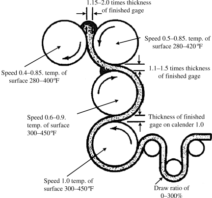
Polymer sheets (greater than 0.01 in thickness) may be produced either by extrusion through thin, flat dies or by calendering (Figure 17.8). Basically, a calender consists of a series of rotating, heated rolls, between which the polymer compound (most often plasticized PVC) is squeezed into sheet form. The thickness of the sheet is determined by the clearance between the rolls. Commercial calenders may be very large (rolls up to 3 ft (1 m) in diameter by 8 ft (3 m) long) and may represent a big capital outlay, but are capable of tremendous production rates (up to 100 yards/min). The polymer may be laminated to a layer of fabric between two rolls to give a supported sheeting. The final rolls may also be embossed to impart a pattern to the sheet. Shower curtains, vinyl upholstery materials (Naugahyde), and vinyl floor tile are produced by calendering.
Figure 17.8 Inverted “L” calender, illustrating process variables for the production of PVC sheet. From Modern Plastics Encyclopedia, McGraw-Hill, New York, 1969–1970 ed.
17.7 Sheet Forming (Thermoforming) [19, 20]
Thermoplastic sheet is converted to a wide variety of finished articles by processes generically known as sheet forming or thermoforming. Although the details vary considerably, these processes all involve heating the sheet above its softening point and forcing it to conform to a cooled mold (Figure 17.9).
Figure 17.9 Sheet-forming process: (a) vacuum forming; (b) drape forming.
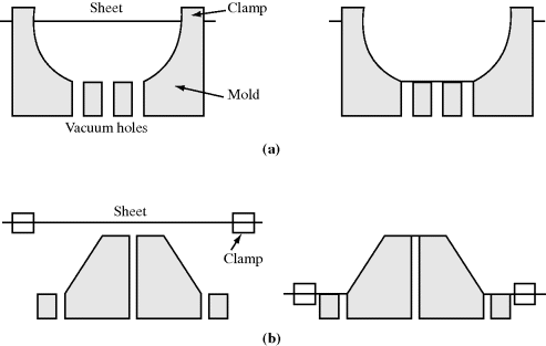
In vacuum forming, for example, the heat-plasticized sheet (either directly from an extruder or preheated in an oven) is drawn against the mold surface by the application of a vacuum from beneath the surface. Similarly, a positive pressure may be used to force the sheet against the mold surface, and where very deep draws are required, mechanical assists, plug forming, are used. In drape forming, the plasticized sheet is draped over a male mold, perhaps with a vacuum assist.
From a material standpoint, polymers used for sheet forming should have high “melt strengths,” that is, high melt viscosities so that they do not draw down or thin out excessively or perhaps even tear in the forming operation. Thus, high molecular weight resins are preferred. One of the great advantages of sheet forming is that relatively inexpensive molds are required since no high pressures are involved. Epoxy molds are often used because they can be easily cast to shape from a handmade pattern.
Among the many familiar items made by sheet forming are drinking cups, meat trays, wraps for cigarette packs, aircraft canopies, corrugated plastic sheets for roofing, lighting globes, and even items as large as the hull of a boat.
A similar technique is used to make sheet molding compound, but requires the addition of several additives, so the discussion is included in Chapter 18.
17.8 Stamping
The plastics industry has long envied the ability to stamp sheet-metal parts with cycle times of a few seconds. Because of the high production rates possible with a stamping process (particularly for forming auto bodies from stamped steel) and the large existing investment in stamping presses, the stamping process has been adapted to form thin-walled (0.1-in) parts from glass-reinforced thermoplastic sheet (Azdel®). The sheet is heated in an infrared oven and then stamped in modified metal-forming equipment, with a dwell time of about 8 s as the material cools in the mold. Because of the thin sections, cooling is rapid and cycle times as low as 15–20 s can be achieved with automated feeding and part-removal systems [21, 22]. So far, the process has been limited to rather simple shapes and shallow draws (crankcase oil pans, battery trays, bucket seat bottoms and backs, etc.), but because of its economic potential, stamping has been combined with other polymer processes (such as thermoforming) in the development of relatively inexpensive high-throughput processes.
17.9 Solution Casting
Solvent-evaporation casting (commonly known as solution casting) produces plastic sheets or films by dissolving the polymer in an appropriate solvent, spreading the viscous solution onto a polished surface, and evaporating the solvent. Additives such as plasticizers and pigments can be easily added to the solution, with a good dispersion achieved in the dried material. In the manufacture of photographic film base, the solution is spread with a “knife” onto a slowly rotating wheel about 2 ft wide and 20 ft in diameter. As the wheel revolves, heated air evaporates the solvent, which is recovered for reuse, and the dried film is stripped from the wheel before the casting point is reached again.
17.10 Casting
The raw materials for many thermosetting polymers are available as low molecular weight liquids that are converted to solid or rubbery materials by a crosslinking reaction. Similarly, liquid vinyl monomers can be converted to solid, linear polymers through an addition reaction. These materials are easily cast to shape at atmospheric pressure in inexpensive molds. A good example of this process is the reproduction of carved wood furniture panels. Only the original is actually carved, which is on expensive step. A mold is made by pouring a room-temperature-curing silicone rubber over the original. When cured, the rubber mold is stripped from the original and used to cast multiple copies from a liquid, unsaturated polyester (Example 2.3). A free-radical initiator causes crosslinking to the final solid object, which faithfully reproduces the detail of the carved original at a fraction of the cost.
Such furniture components provide a good example of how the processing method of choice often depends on the production volume. They can also be injection molded from, for example, high-impact polystyrene. Because the panels are usually large, they require a large and very expensive molding machine. Similarly, the mold, with its intricate carving and wood-grain detail in hardened steel, is very expensive to produce. Thus, the capital outlay for injection-molded panels is huge, while the reverse is true for cast panels. Nevertheless, parts can be injection molded with cycle times under a minute and very little hand labor involved, and when the capital investment is amortized over a large number of panels, it becomes a small contribution to the total panel cost. On the other hand, the long cure times and hand labor required for the casting process make it prohibitively expensive for large production runs, but it is the preferred process for small numbers of parts.
Delicate electrical components are often encapsulated or “potted” by casting a thermosetting liquid resin (usually an epoxy) around them. The casting of acrylic sheet from monomer or syrup is described in Chapter 12.
17.11 Reinforced Thermoset Molding
Many plastics, when used by themselves, do not possess enough mechanical strength for structural applications. When reinforced with high-strength fibers, however, the composites have high strength-to-weight ratios and can be fabricated into a wide variety of complex shapes. Glass and other fibers are used extensively to reinforce thermosetting plastics, mostly polyesters and epoxies. Fiberglass-reinforced plastics (FRPs) are now used for just about all boats under 40 ft in length, truck cabs, automobile body panels, structural panels, aircraft components, and bathtubs.
Many such objects are fabricated by a process known as hand layup. The mold surface is often first sprayed with a pigmented but nonreinforced gel coat of the liquid resin to provide a smooth surface finish. The gel coat is followed up by successive layers of fiberglass, either in the form of woven cloth or random matting, impregnated with the liquid resin, which is then cured (crosslinked) to give the finished product.
This process is tremendously versatile. The molds are relatively inexpensive, because no high pressure is required. Objects may be selectively reinforced by adding extra layers of material where desired. The major drawback of the process is the expense of hand labor involved, which makes it uneconomical for large production volumes. For this reason, a sprayup process is often used. A special gun chops continuous fibers into approximately 1 in lengths. The chopped fibers are combined with a stream of liquid resin and sprayed directly onto the mold surfaces. Although the random chopped fibers do not reinforce quite as well as woven cloth or random mat, the labor savings are substantial. Sprayed-on polyester-fiberglass backings are also applied to vacuum-formed poly(methyl methacrylate) sheets, thus combining a smooth, hard, strain- and UV-resistant acrylic surface skin with the lightweight strength of a FRP core. Such composites are used for sinks, bathtubs, and recreational vehicle bodies.
In many objects, stresses are not uniformly distributed, so the reinforcing fibers may be arranged to support the stress most efficiently. In “fiberglass” or “graphite” fishing rods, vaulting poles, golf club shafts, etc., the fibers are arranged along the long axis to resist the bending stresses applied. The process of filament winding extends this principle to more complex structures. Continuous filaments of the reinforcing fiber are impregnated with liquid resin and then wound on a rotating mandrel. The winding pattern is designed to resist most efficiently the anticipated stress distribution. The range of the Polaris submarine ballistic missile was increased by several hundred miles by replacing the metallic rocket casing with a filament-wound reinforced plastic system. This technique is also used to produce tanks and pipe for the chemical process industries, and even gun barrels, by filament winding about a thin metal core that provides the necessary heat and abrasion resistance.
More recently, nanofibers (particularly carbon nanotubes) have found their way into fibrous polymer composites, offering even greater strength per mass when compared to composites made using the larger fibers above.
Pultrusion [23] is used to produce continuous lengths of objects with a constant cross section, for example, structural beams. Continuous fibers (such as roving that is made into yarn) and/or mat are impregnated by passing them through a tank of liquid resin and pulling slowly through a heated die of the desired cross section. The resin cures to a solid as it passes through the die.
17.12 Fiber Spinning
The polymers used for synthetic fibers are similar, and in many cases, identical to those used as plastics, but for fibers, the processing operation must produce an essentially infinite length-to-diameter ratio. In all cases, this is accomplished by forcing the plasticized polymer through a spinnerette, a plate in which a multiplicity of holes has been formed to produce the individual fibers, which are then twisted together to form a thread for subsequent weaving operations. The cross section of the spinnerette holes obviously has a lot to do with the fiber cross sections, which, in turn, greatly influences the properties of the fiber. The three basic types of spinning operations differ mainly in the method of plasticizing and deplasticizing the polymer.
Melt spinning is basically an extrusion process. The polymer is plasticized by melting and pumped through the spinnerette. The fibers are usually solidified by a cross-current blast of air as they proceed to the drawing rolls. The drawing step stretches the fibers, orienting the molecules in the direction of stretch and inducing the high degrees of crystallinity necessary for good fiber properties. Nylons are commonly melt spun.
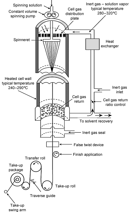
In dry spinning, a solution of the polymer is forced through the spinnerette. As the fibers proceed downward to the drawing rolls, a countercurrent stream of warm air evaporates the solvent (Figure 17.10). In this process, the cross section of the fiber is determined not only by the shape of the spinnerette holes but also by the complex nature of the diffusion-controlled solvent evaporation process, because there is considerable shrinkage as the solvent evaporates. The acrylic fibers (Orlon®, Creslan®, Acrilan®, etc.), mainly polyacrylonitrile, are produced by dry spinning.
Figure 17.10 Dry spinning of polymer fibers [24]. Reprinted with permission of John Wiley and Sons, Inc.
Wet spinning is similar to dry spinning in that a polymer solution is forced through the spinnerette. Here, however, the solution strands pass directly into a liquid bath. The liquid might be a nonsolvent for the polymer, precipitating it from solution as the solvent diffuses outward into the nonsolvent. The bath might also contain a substance that precipitates a polymer fiber by chemically reacting with the dissolved material. Here again, the process as well as the spinnerette influences the fiber cross section. Kevlar is an example of a wet-spun fiber (Section 4.8). The polymer is dissolved in concentrated sulfuric acid and the solution is spun into a water bath. The water leaches out the acid, causing the polymer to precipitate in fiber form.
17.13 Compounding
Polymers are almost always used in combination with other ingredients. These ingredients are discussed in subsequent chapters, but they must be combined with the polymer in a compounding operation.
Occasionally, if they do not interfere with the polymerization reaction, such ingredients may be incorporated at the monomer or low molecular weight polymer (e.g., unsaturated polyester, Example 2.3) stage and carried through the polymerization and/or crosslinking reaction. In such cases, viscosities are low enough to permit the use of standard mixing equipment. Similarly, powdered PVC and thermosets are compounded with other ingredients in the usual tumbling-type of blending equipment.
Because of their extremely high melt viscosities, specialized equipment, however, is usually needed to compound ingredients with high molecular weight thermoplastics. In general, high shear rates and large power inputs per unit volume of material are required to achieve a uniform and intimate dispersion of ingredients in the melt. Single- and twin-melt extruders (Section 3) are used extensively for continuous compounding. The latter, with screws often modified to incorporate special mixing sections, are better mixers and provide a narrower, more uniform distribution of residence times, while the formed offer lower cost and greater mechanical simplicity. Intensive mixers, such as the Banbury mixer (Figure 17.11), subject the material to high shear rates and large power inputs in a closed, heated chamber containing rotating, intermeshing blades.
Figure 17.11 Banbury mixer. From L.K. Arnold, Introduction to Plastics, Iowa State UP, Ames (1968).
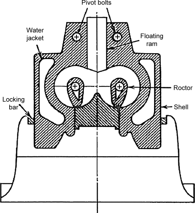
A two-roll mill (Figure 17.12) generates high shear rates in a narrow nip between two heated rolls that counter-rotate with slightly different velocities. In commercial mills, the rolls are about 1 ft in diameter and 3 ft long. Once the polymer has banded on one of the rolls, ingredients are added to the bank between the rolls. The band is cut off the roll with a knife, rolled up, and fed back to the nip at right angles to its former direction. This is done several times to improve mixing. Despite extensive safety precautions, operators of two-roll mills often have n fingers (n < 10). To the author's knowledge, no systematic studies of the effect of the additional (10−n) ingredients on the properties of the compounded polymers have been reported.
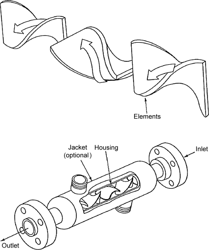
Motionless or static mixers are a more recent development for continuous compounding [25–27]. One example of this type of device, the Kenics mixer (Figure 17.13), consists of a series of alternating right- and left-handed helices that continuously divide the melt and cause it to rotate around its own hydraulic axis. Each element in a Kenics mixer breaks the stream into two parts. Therefore, an n-element mixer generates 2n layers, so n does not have to be very large to achieve intimate mixing. The obvious advantage of this type of device is that it contains no moving parts (although the material must be pumped through it). It also requires relatively low power input per unit of material processed. Such mixers provide good radial mixing and relatively narrow residence-time distributions, despite the fact that the flow is invariably laminar in the processing of polymer melts. They are also incorporated in extruders, between the screw and die, and in injection-molding machines ahead of the nozzle to improve the thermal homogeneity of the melt.
Figure 17.13 The Kenics Static Mixer. From McCabe W.L., J.C. Smith, and P. Harriott, Unit Operations of Chemical Engineering, 4th ed., McGraw-Hill, New York, 1985.
17.14 Lithography
Lithography, literally stone writing, has been used to etch patterns into solid materials (primarily harder materials than polymers), and has been used extensively in microelectronics to etch fine and complex patterns into silicon wafers to make integrated circuits. A photoresist, usually made of a polymer, is made to block an intense light, resulting in the reverse pattern being etched into the wafer. For polymer processing, similar photoresists (or masks) are placed between a light source and a monomer or pre-olymer solution containing a photoinitiator. After polymerization, unreacted solution behind the mask can be removed, resulting in polymer films with features that approach submicron sizes that match the holes in the mask. The mask is recycled, similar to the molds used in injection molding. Photolithography is best suited for small parts (films) that require complex two-dimensional features, but can be used for high-volume production.
Electron beam lithography is a similar process, but instead of using light, a beam of electrons is shot at a surface to create the surface architecture with the advantage of being able to produce even smaller features (into the nanometer region, as electron beams can be focused to dimensions smaller than the wavelength of light).
17.15 Three-Dimensional (Rapid) Prototyping
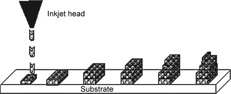
A more recent addition to the methods of polymer processing is inkjet printing or three-dimensional prototyping. Here, polymer droplets can be placed using a machine similar to an inkjet printer to build complex three-dimensional architectures, usually with the assistance of computer-aided design (Figure 17.14). This is a rather expensive technique in that (even with rapid prototyping) the time required to make each part can be fairly lengthy. However, there is one really great advantage: the interior architecture of a polymeric part can be designed with a great deal of geometric specificity, much more complex than can be achieved by blow molding or extrusion. This allows void spaces to be built into materials, such as conduits for flow, but in three dimensions. One area of application is in light-emitting diode (LED) displays used in televisions and computer screens. They are also useful in three-dimensional reconstructions.
Figure 17.14 Rapid prototyping method using an inkjet printer head to construct three-dimensional objects. After leaving the head, the droplets coalesce, and by rastering over a region multiple times, a three-dimensional object can be made.
17.16 Summary
Because polymer properties can be easily modified by addition of solvents, plasticizers, or heat, they are quite versatile when selecting a production method. This gives rise to a wide range of processing techniques (summarized in Table 17.1), but also presents challenges. Not every technique will work for each type of polymer, e.g., thermosets and polymers that degrade easily cannot be melt processed. On the other hand, starting with a liquid (monomer, prepolymer, polymer solution, or polymer melt) allows polymers to be somewhat easily formed into rather complex (sometimes large) shapes with a great degree of reproducibility. Although the major techniques used in polymer processing have been presented in this chapter, numerous variations and combinations continue to evolve to allow processing of new polymers and develop economical methods to create even more complex products. Chapters 18 to 22 include some additional processing techniques, but is focused on additives (as in sheet molding compound) or on more specifically applied areas (such as surface finishing and microencapsulation).
Problems
| (a) computer keyboards | (b) rubber tires |
| (c) contact lenses | (d) mylar balloons |
| (e) acrylic fibers for clothing | (f) car windshields |
| (g) a bottle for liquid detergent |
1. Kroschwitz, J. (ed.), Encyclopedia of Polymer Science and Engineering, 2nd. ed., Wiley, New York, 1985.
2. Modern Plastics Encyclopedia, McGraw-Hill, New York (yearly).
3. Rosato, D.V. and D.V. Rosato, Plastics Processing Data Handbook, Van Nostrand Reinhold, New York, 1989.
4. Morton-Jones, D.H., Polymer Processing, Chapman and Hall, London, 1989.
5. Han, C.D., Rheology in Polymer Processing, Academic, New York, 1976.
6. McKelvey, J.M., Polymer Processing, Wiley, New York, 1962.
7. Middleman, S., Fundamentals of Polymer Processing, McGraw-Hill, New York, 1977.
8. Pearson, J.R.A., Mechanics of Polymer Processing, Elsevier, New York, 1985.
9. Pearson, J.R.A. and S.M. Richardson (eds), Computational Analysis of Polymer Processing, Applied Science, New York, 1983.
10. Tadmor, Z. and C.G. Gogos, Principles of Polymer Processing, Wiley-Interscience, New York, 1979.
11. Rosato, D.V. and D.V. Rosato, Injection Molding Handbook, Van Nostrand Reinhold, New York, 1985.
12. Rubin, I.I., Injection Molding: Theory and Practice, Wiley-Interscience, New York, 1973.
13. Macosko, C.W., Fundamentals of Reaction Injection Molding, Hanser, Munich, 1988.
14. Stevens, M.J., Extruder Principles and Operation, Elsevier, New York, 1985.
15. Tadmor, Z. and I. Klein, Engineering Principles of Plasticating Extrusion, Van Nostrand Reinhold, New York, 1970.
16. Rauwendaal, C., Polymer Extrusion, Hanser, Munich, 1986.
17. Private communication to S.L. Rosen, NRM Corporation.
18. Rosato, D.V. and D.V. Rosato (eds), Blow Molding Handbook, Hanser, Munich, 1989.
19. Gruenwald, G., Thermoforming: A Plastics Processing Guide, Technomic, Lancaster, PA, 1987.
20. Throne, J.L., Thermoforming, Hanser, Munich, 1987.
21. Sikes, S., Mod. Plast. 51(1), 70 (1974).
22. Ward, L.G., Plast. Eng. 35(4), 47 (1979).
23. Meyer, R.W., Handbook of Pultrusion Technology, Chapman and Hall, London, 1985.
24. Boliek, J.E. and A.W. Jensen, Fibers, Elastomeric, in Kirk-Othmer Encyclopedia of Chemical Technology, Wiley, 2009, p. 15.
25. Skoblar, S.M., Plast. Technol. October 1974, p. 37.
26. Schott, N.R., B. Weinstein, and D. LaBombard, Chem. Eng. Prog. 71(1), 54 (1975).
27. Chen, S.J., Chem. Eng. Prog. 71(8), 80 (1975).