Manual transmissions (gearboxes) are still found in some boats. These are generally of the planetary, or epicyclic, type. Far more common are hydraulic planetary transmissions and two-shaft transmissions, with the latter dominating the marketplace in the past decade (in other words, as time goes by, we will see fewer and fewer planetary transmissions, either hydraulic or manual).
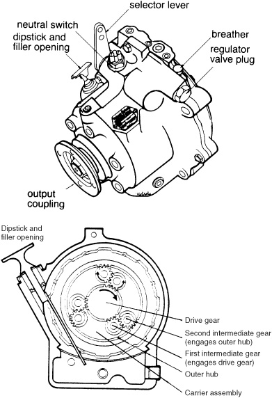
With a planetary transmission (manual or hydraulic), the engine turns a geared driveshaft (the drive gear) that rotates constantly in the same direction as the engine. Deployed around and meshed with a gear on this shaft are two or three gears (the first intermediate gears) on a carrier assembly. These mesh with more gears (the second intermediate gears), also mounted on the carrier assembly. The second intermediate gears engage a large geared outer hub. The carrier assembly, with its collection of first and second intermediate gears, is keyed to the output shaft of the transmission (see Figure 8-1).
The forward clutch is on one end of the driveshaft. Engaging forward locks the entire driveshaft and carrier assembly together—the whole unit rotates as one, imparting engine rotation to the output shaft of the transmission via the carrier assembly (see Figure 8-2). This is very efficient because no gears are involved in imparting drive to the output shaft.
Reverse is a little more complicated. The forward clutch is released and a second clutch is engaged. This locks the outer geared hub in a stationary position. Meanwhile the drive gear is still rotating the intermediate gears. Unable to spin the outer hub, the intermediate gears rotate around the inside of the hub in the opposite direction to the drive gear. The carrier assembly imparts this reverse motion to the output shaft (see Figure 8-3). There are some energy losses in the gearing.
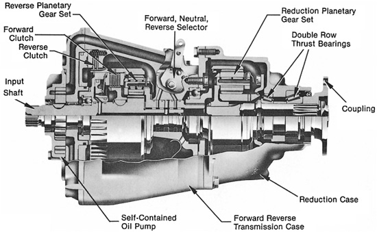
Manual and hydraulic versions of a planetary box are very similar. The principal difference is that the reverse clutch of a manual box consists of a brake band that is clamped around the hub (see Figure 8-4), whereas in a hydraulic box, a second clutch, similar to the forward clutch, is used (see Figure 8-5).
A manual box uses pressure from the gearshift lever to engage and disengage the clutches. A hydraulic box incorporates an oil pump; the gearshift lever merely directs oil flow to one or the other clutch, with the oil pressure doing the actual work. While quite a bit of pressure is needed to operate a manual transmission, shifting gear with a hydraulic transmission is a fingertip affair.
FIGURE 8-1. A typical planetary transmission (top). The internal view (bottom) shows the gears as having teeth only partway around, to illustrate how they mesh, but the gears actually have teeth all the way around. (Courtesy BorgWarner)
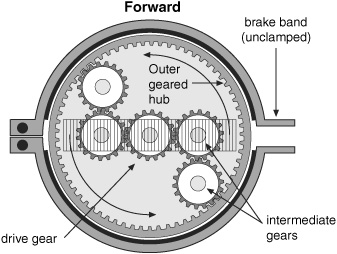
FIGURE 8-2. In forward gear in a planetary transmission, the brake band is unclamped while the forward clutch locks the drive gear, carrier assembly, and geared hub together so that they rotate as one (schematically represented by the band across the center of the illustration). Engine rotation is imparted to the output shaft. (Michael D. Ryus)
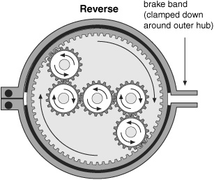
FIGURE 8-3. When in reverse in a planetary transmission, the forward clutch is released, leaving the carrier assembly free to rotate around the drive gear, while the brake band is clamped down, locking the geared hub. The carrier assembly is driven around the hub in the opposite direction to the drive gear, imparting reverse rotation to the output shaft. (Michael D. Ryus)
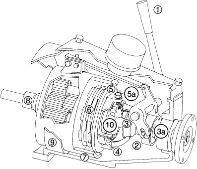
FIGURE 8-4. Operating principles of a Paragon S-A-O manual planetary transmission. For forward, the gear lever (1) is pushed toward the engine; the shift yoke (2) moves back the opposite way (toward the coupling), sliding the shift cone (3) along the output shaft (3a), thus moving out the cam levers (4). The cam levers bear on the pressure plate (5), compressing the friction discs (6) in the clutch. The friction discs press against the gear carrier (7), causing the motion of the input shaft (8) to be transmitted to the output shaft (3a). The pressure plate is adjusted by backing out the lock bolt (5a), screwing up the castellated nut (10), and retightening the lock bolt. For reverse, the gear lever (1) is moved the opposite way, compressing the reverse band (9), which locks around the gear carrier like a huge hose clamp. (Jim Sollers)
FIGURE 8-5. A hydraulic planetary transmission. (Courtesy BorgWarner)
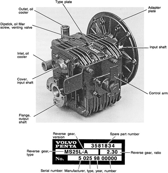
The simplest form of a two-shaft transmission (see Figure 8-6) has the engine coupled to the transmission’s input shaft, to which two gears are keyed, one at either end. A second shaft, the output shaft, has two more gears riding on it; one of these engages one of the input gears directly, and the other engages the second input gear via an intermediate gear (see Figure 8-7). These two output gears are mounted on bearings and freely rotate around the output shaft.
The drive gears impart continuous forward and reverse rotation to the output gears. Each output gear has its own clutch, and between the two clutches is an engaging mechanism. Moving the engaging mechanism one way locks one gear to the output shaft, giving forward rotation; moving the mechanism the other way locks the other gear to the shaft, giving reverse rotation (see Figures 8-7 and 8-8).
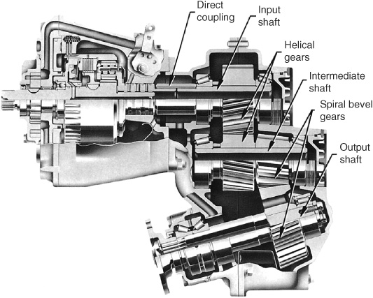
Larger two-shaft transmissions may have more shafts and gears in order to achieve gear reductions that lower the speed of the output shaft and perhaps change the angle of the output shaft. However, if you mentally strip away the extra gears, the underlying operating principle is as described above. On smaller two-shaft transmissions, the case is in two halves that come apart to reveal all the contents; on larger ones, the end housings are generally unbolted (see Figure 8-9).
In a manual two-shaft transmission, when the clutch-engaging mechanism is first moved to either forward or reverse, it gently presses on the relevant clutch. This initial friction spins a disc carrier, which holds some steel balls in tapered grooves. The rotation drives the balls up the grooves. Because of the taper in the grooves, the balls exert an increasing pressure on the clutch, completing the engagement (see Figure 8-10). Only minimal pressure is needed to set things in motion, and thereafter, a clever design supplies the requisite pressure to make the clutch work, but without the necessity for oil pumps or oil circuits. Shifting gear is once again a fingertip affair.
In a hydraulic two-shaft transmission, an oil pump provides the pressure for operating the clutches, just as in a hydraulic planetary transmission.
FIGURE 8-6. A small, manual Volvo Penta two-shaft transmission. The popular Hurth transmissions are very similar. (Courtesy Volvo Penta)
A V-drive is an arrangement of gears that allows the engine to be installed “backward,” placing it directly over the output shaft (see Figure 8-11). This enables more compact engine installations to be made, and in particular, enables sportfishing boats and other planing-type hulls to have the engine installed in the stern of the boat, which is the best spot from the point of view of weight distribution. All transmission types can be used with V-drives.
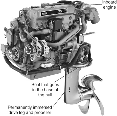
Inboard/outboards (see Figures 8-12 and 8-13) are exactly what their name implies: an inboard engine coupled to an outboard motor-type drive assembly and propeller arrangement with a universal joint (U-joint) that allows the drive unit to be raised and lowered and turned from side to side. These units have definite advantages in planing craft, notably:
FIGURE 8-7. A two-shaft Hurth transmission with the cover removed (top). With the forward clutch engaged (bottom left), the output shaft rotates in the opposite direction to the input shaft. With the reverse clutch engaged (bottom right), the output shaft rotates in the same direction as the input shaft via the intermediate gear. (Courtesy Hurth)
FIGURE 8-8. Forward (top) and reverse (bottom) in a two-shaft transmission with additional reduction and shaft-anglechanging gearing. (Courtesy Volvo Penta)
FIGURE 8-9. Removing the end cover from a larger two-shaft transmission. It would have been a good idea to clean the exterior before working on it! Note the extensive rusting of the internal parts due to saltwater intrusion (the boat in which the transmission was installed sank).
• Inboard/outboards allow an engine to be mounted in the stern of the boat, which is often the best place in terms of weight distribution on many planing hulls.
• The outboard unit can be pivoted up and down hydraulically. This enables these boats to take full advantage of their shallow draft to run up onto beaches. It also permits infinite propeller-drive-angle to hull attitude adjustments for changes in boat trim and makes trailering easy.
• The whole outboard unit turns for steering, greatly increasing maneuverability and removing the need for a separate rudder.
• There is no propeller shaft, stern tube, or stuffing box to leak into the boat.
Naturally, there are drawbacks:
• The extra gearing and sharp changes in drive angle absorb more power than a conventional transmission.
• The U-joints in the transmission tend to have a relatively high failure rate if driven hard.
• Above all, most outboard units are built of relatively corrosion-susceptible materials. If the boat is dry-docked between use, or the outboard unit is raised out of the water, this is not a great problem; but if the unit is left in the water, it can be (see the Aluminum Castings and Corrosion sidebar).
Observing all maintenance schedules is important, particularly oil changes, greasing of U-joints, and replacing those all-important zincs. The U-joint is protected by a rubber boot or bellows that needs to be checked for signs of cracking or other defects. If you find any problems, immediately replace the boot to avoid expensive damage to the U-joint.
Note: When changing the oil in a sterndrive unit, check the manual for the procedure. Most have to be tilted up (e.g., Volvo Pentas, to 35 degrees). If the old oil is discolored, there is a problem.
ALUMINUM CASTINGS AND CORROSION
There are two common methods for making the aluminum cases for inboard/outboard drive legs (and also saildrive legs): pressure die-casting, and using permanent molds. The nature of the two processes requires the use of different alloys, with the permanent-mold approach using more corrosionresistant alloys. This is important to the boatowner!
You cannot tell by looking at any particular unit what alloy has been used. As far as I know, all MerCruiser units use pressure die-casting, as do Volvo Penta units on gasoline-powered inboard/outboards, whereas the Volvo Pentas coupled to diesel engines use the more corrosion-resistant permanent molding.
Following manufacture, all units are given special paint jobs that are designed to seal the surface of the aluminum and prevent corrosion. They are then protected with sacrificial zinc anodes (and sometimes with impressed-current cathodic protection, which is beyond the scope of this book). It is absolutely critical to maintain the zincs, replacing them when they are no more than 50% depleted. For boats operating in fresh water, Volvo Penta recommends exchanging the zinc anodes for magnesium anodes (available from Volvo Penta).
If the paint barrier on an outboard drive (or saildrive) gets damaged, you will need to repair it. This requires that you clean down to bare metal, using aluminum oxide sandpaper to avoid leaving contaminants that would promote corrosion.
The next step is to acid-etch and seal the aluminum before repainting; it’s best to get advice from the inboard/outboard (or saildrive) manufacturer on what to use and how to apply it. Also, check with the manufacturer for compatible bottom (antifouling) paints. Copper-based paints are likely to be destructive to the aluminum.
Any boat that has aluminum below the waterline and an onboard AC electrical system is asking for trouble whenever the boat is plugged into shore power if the shore-power inlet on the boat does not have a capacitor-type galvanic isolator, or better yet an isolation transformer. (See my Boatowner’s Mechanical and Electrical Manual for an extensive discussion of this.)
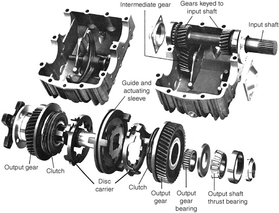
FIGURE 8-10. A disassembled Hurth two-shaft transmission. (Courtesy Hurth)
FIGURE 8-11. A V-drive planetary transmission. (Courtesy BorgWarner)
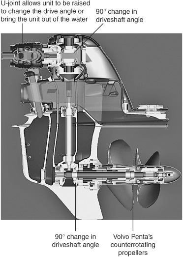
FIGURE 8-12. A Volvo Penta inboard/outboard. (Courtesy Volvo Penta)
Saildrives are an adaptation of an inboard/outboard in which the drive leg is permanently immersed and cannot be tilted up and down (see Figure 8-14). At the top of the drive leg, a gear and clutch arrangement similar to that in a two-shaft transmission enables the unit to be put into forward and reverse (see Figure 8-15).
Many boatbuilders, especially in Europe, like saildrives because they are much easier to install than a traditional engine and take up less room.
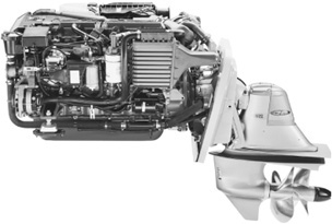
FIGURE 8-13. An inboard/outboard unit coupled to an inboard engine. (Courtesy Volvo Penta)
FIGURE 8-14. A Volvo saildrive unit. (Courtesy Volvo Penta)
Essentially, you cut a big hole in the bottom of the boat, then bond in an adapter plate. The engine and its leg bolt to this adapter plate, which is sealed into the bottom of the boat by a large rubber diaphragm. There is no stern tube, shaft seal, or stern (Cutless) bearing; no engine alignment is required. The total cost of an installation (engine, transmission, and installation) is significantly less than that of a traditional installation.
From the boatowner’s perspective, a saildrive eliminates the hassles associated with the shaft seal found in a conventional propeller shaft installation. Saildrives are also soft mounted, eliminating much vibration and making for quieter operation. They are reputed to offer less drag under sail (I can’t confirm this, except to note that many racing boats use them).

FIGURE 8-15. The operating principles of a saildrive. (Courtesy Volvo Penta)
Saildrives may have higher mechanical losses than a transmission and shaft seal because of the two right-angle changes of drive direction. But because the propeller is put in the water in the horizontal plane (as opposed to the propeller shaft being angled downward, as it is in most conventional installations, to give the propeller sufficient clearance beneath the hull), the propeller is more efficient at moving the boat (saildrive manufacturers claim 10% to 12% improved efficiency).
The single biggest drawback of saildrives is corrosion (see the Aluminum Castings and Corrosion sidebar). The drive leg is aluminum and, if not properly installed, it can rapidly become a giant galvanic anode with respect to the rest of the boat’s underwater metal (and that of other boats when plugged into shore power without some form of galvanic isolation). Thus the drive leg should be electrically isolated and adequately protected with sacrificial zincs.
Saildrives come with attached zincs, which need regular attention and must be replaced before 50% of the anode has been consumed; if neglected, loss of the zinc can result in expensive damage. In terms of other maintenance, Volvo Penta recommends replacing the diaphragm that seals the saildrive in the bottom of a boat every seven years, but few owners do this. Many saildrives over twenty years old are still operating with the original diaphragms.
Other than corrosion, the most likely source of saildrive problems is getting monofilament fishing line up the back of the propeller and winding this into the shaft seal, damaging it. The boat will have to be hauled to replace the seal.
Note: There have been a number of reports regarding Volvo Penta saildrives and total zinc loss as a result of galvanic corrosion between the zinc and its fasteners (causing the zincs to fall off). A much better way to manufacture zincs and prevent their loss is to cast them around a steel plate that the fasteners go through. Keep an eye on those zincs!
The Volvo Penta Inboard Performance System (IPS) was introduced in 2005. It packages an electronically controlled common rail diesel engine with a specially constructed saildrive unit that has twin counterrotating, forward-facing propellers (see Figures 8-16 and 8-17). It is only available for twin-engine installations, and includes electronic (fly-by-wire) throttle, gear shifting, and steering.
The net result is a simple installation that has significant efficiency and performance benefits over a traditional engine and propeller shaft installation, with lowered emissions and greater maneuverability at both low and high speeds. Volvo Penta’s trademark counterrotating propellers (invented by Volvo and pioneered on their inboard/outboard units) cancel out any tendency for prop walk. The two propellers result in a greater blade area than on a single propeller installation. This makes the propellers less sensitive to loading (i.e., less cavitation and lower tip losses—see Chapter 9). The forwardfacing propellers operate in relatively undisturbed water, which further improves efficiency. Of course, if you don’t have a keel, they are also the first thing to hit the bottom if you run out of water.
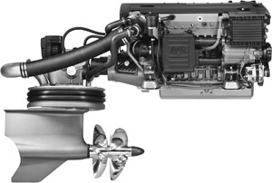
FIGURE 8-16. The Volvo Penta Inboard Performance System. (Courtesy Volvo Penta)
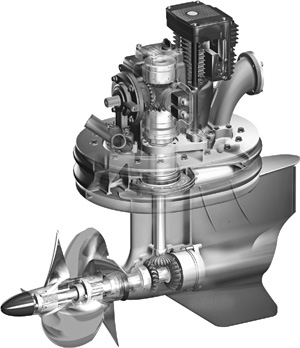
FIGURE 8-17. A cutaway of the IPS drive leg that, in essence, is an adaptation of a saildrive leg. (Courtesy Volvo Penta)
Other than the counterrotating propellers, the various technical innovations—common rail injection, electronic engine controls, and a saildrive— have been covered elsewhere (see Chapter 2 and above). The case of the drive leg is manufactured from nibral (a nickel-bronze-aluminum alloy), which is rugged, highly corrosion resistant, and naturally resistant to biofouling (it will need scrubbing once in a while).
When a boat is being towed or is under sail with the motor shut down, the flow of water over a fixed-blade propeller (for more on propellers, see Chapter 9) will spin the propeller unless the propeller shaft is locked in some way. This is of little concern with manual and two-shaft transmissions, except that it creates unnecessary wear on bearings, oil seals, and the shaft seal. But on some hydraulic transmissions, it will lead to a complete failure of the transmission since no oil is pumped to the bearings when the engine isn’t running. Some output-shaft oil seals (particularly rawhide seals found on some really old transmissions) also will fail. Freewheeling propellers can also make quite a racket.
You can lock the propeller shaft on a manual transmission simply by putting the transmission in gear. The same holds for two-shaft transmissions. Note that you must always lock the transmission in the opposite direction to that in which the boat is moving (e.g., if sailing or being towed forward, put the transmission in reverse). If you don’t, the clutch may slip and burn up (the critical speed at which this happens on Hurth transmissions and Hurth look-alikes seems to be around 6 knots).
A hydraulic transmission cannot be locked by putting it in gear. Without the engine running, the oil pump will not be working, and there will be no oil pressure to operate the clutches. You need a shaft brake (except with folding and feathering propellers), and you have essentially two choices.
Hydraulically operated shaft brakes all have a springloaded piston riding in a cylinder that has an oil line plumbed to the transmission oil circuit. When the engine is at rest, the spring forces the piston down the cylinder to operate the brake. When the engine is started, oil pressure from the transmission oil pump forces the piston back up the cylinder against the spring pressure, releasing the brake. These units are thus automatic in operation, overcoming the main objection to older manual units, which was the probability of leaving the brake on, putting the transmission in gear, and burning up the brake.
Four variations on the hydraulic theme are widely available:
1. Caliper disc. These operate as on a car. A disc is bolted between the two propeller shaft coupling halves. A hydraulically operated caliper grips the disc to stop rotation (see Figure 8-18).
2. Cam disc. Similar to the above except that the disc has several cams. A hydraulically operated arm locks into the cams.
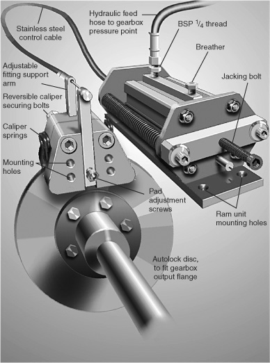
FIGURE 8-18. A hydraulic shaft lock. (Courtesy Brunton’s Propellers)
3. Brake band. A hydraulically operated brake band clamps around the propeller shaft coupling.
4. Plunger type. A slotted sleeve is clamped around the shaft, and a hydraulically operated plunger locks into one of the slots.
On older manual units, a brake pad clamps around a block on the shaft or coupling. There is the obvious inherent risk that an owner will forget to disengage the brake when he or she next starts the engine and will burn up the brake. Newer manual units, however, have a notched disc clamped to the propeller shaft, with a plunger engaging the notch. If the brake is left engaged when the engine is started and put in gear, the plunger is simply forced out of the notch and held back by another springloaded pin until it is set manually once again (see Figures 8-19 and 8-20).

FIGURE 8-19. A manual propeller shaft lock. (Courtesy Shaft Lok)
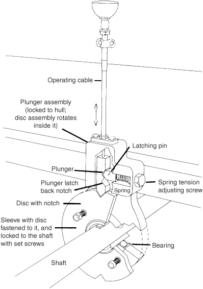
FIGURE 8-20. Anatomy of a manual shaft lock. (Jim Sollers)
• On hydraulic units, any oil leaks through faulty piston seals, connections, or hoses will cause the loss of the transmission oil and ultimately transmission failure. Adding a hydraulic shaft lock may, in fact, void a transmission warranty.
• The manual plunger types have a tendency to jump out during hard sailing. Spring tension on the latching pin can be increased to hold the plunger in place, but then it becomes more difficult to disengage the plunger.
• The cam disc, hydraulic plunger, and manual notched-disc plunger-style units can be set only at low propeller speeds. Ignoring this is likely to cause damage to the first unit; with the second and third units, the plunger will jump out. It may be necessary to slow the boat and reduce propeller freewheeling before engaging the device; in other words, these devices are shaft locks rather than shaft brakes.
Pay close attention to the hydraulic lines and inspect them regularly for any signs of leaks around the piston seals. Check the brake linings on caliper and brake band units for wear. Don’t allow them to slip—a lot of heat will be generated. Check any sleeve mounting bolts from time to time.
The control cable is a Morse cable. Figure 8-27 on page 217 shows a number of points to watch for with Morse cables. The plunger unit is mounted on a bearing within which the propeller shaft rotates. The bearing is sealed for life. Check for undue play once in a while, and while you’re at it, also check the setscrews that lock the central sleeve to the propeller shaft. If water is being thrown around this area (generally from a leaking shaft seal), the bearing will rust out over time.
Transmission maintenance is minimal (see Figure 8-21). It generally boils down to the following:
• Keep the exterior of the transmission clean, which is important for detecting oil leaks.
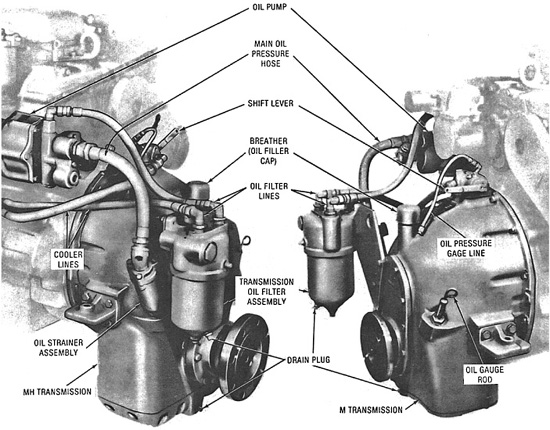
FIGURE 8-21. Principal external components on a relatively large hydraulic transmission. (Courtesy Detroit Diesel)
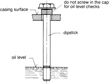
FIGURE 8-22. Checking the oil level on a Hurth transmission. (Courtesy Hurth)
• Periodically check the oil level (see Figure 8-22). Unless there is a leak, it should never need topping off.
• Check for signs of water contamination. Water emulsified in engine oil gives the oil a creamy texture and color. In automatic transmission fluid, it looks more like a strawberry frappe!
• Change the oil annually. Check the color— a slipping clutch will turn the oil black.
Most transmissions operate on 30-weight engine oil or automatic transmission fluid (ATF type A—normally Dextron II or Dextron III; the latter is an improved formulation of the former and is interchangeable with it). Note that mixing some different types of transmission fluids (e.g., A and F types) can destroy transmission seals, so be sure to stick with whatever the manufacturer specifies.
If there is an oil screen or a magnetic plug (or both) in the base of the transmission, inspect them for any signs of metal particles or other internal damage when changing the oil. Some transmissions have an oil filter beneath the oil filler cap that will need replacing. Before checking the new oil level, run a hydraulic transmission for a couple of minutes, then shut it down to make the check. On some transmissions, the dipstick must be screwed completely in to check the level; on others the threaded portion is kept on top of the housing—check the manual.
If the transmission has a raw-water-cooled oil cooler with a sacrificial zinc anode, you must check the zinc anode regularly and change it when only partly eaten away.
The majority of transmission difficulties arise as a result of improper clutch adjustments (manual transmissions) or problems with the control cables, rather than from problems with the transmission itself (see below; manual two-shaft transmission clutches, in particular, are very sensitive to improper cable adjustments). However, before discussing these issues, there are a couple of problems peculiar to hydraulic boxes that I want to note.
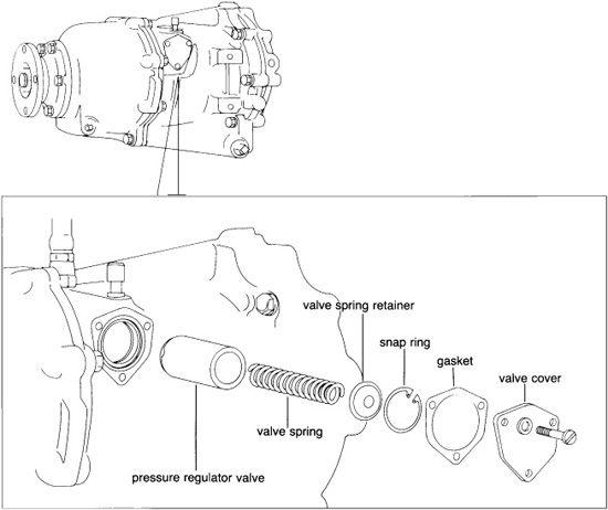
A buzzing sound indicates air in the hydraulic circuit, generally as a result of a low oil level. This will lead to a loss of pressure and slipping clutches. Most hydraulic transmissions also have an oil pressure regulating valve that passes oil back to the suction side of the oil pump if excess pressure develops. If the valve sticks in the open position, the clutches may slip or not engage at all. On the other hand, if the valve sticks closed, the clutches will engage roughly (as they also will do if gears are shifted at too high an engine speed). The valve is generally a spring-loaded ball or piston screwed into the side of the transmission—removing it for inspection and cleaning is easy (see Figure 8-23).
The top of most manual transmissions unbolts and lifts off. Inside are adjustments for forward and reverse gears. On those models with a brake band for reverse (the majority in small boats), reverse is easier.
To adjust the reverse clutch, move the gear lever into and out of reverse—the brake band will be clearly visible as it clamps down on the hub and unclamps (refer back to Figure 8-4). On one side of the band will be an adjusting bolt. If the transmission is slipping in reverse, tighten the bolt a little at a time, engaging reverse between each adjustment. Adjustment is correct when the gear lever requires firm pressure to go into gear, and clicks in with a nice, clean feel.
FIGURE 8-23. An oil pressure regulating valve. (Jim Sollers)
It is important not to overdo things. Put the box in neutral and spin the propeller shaft by hand. If the brake band is dragging on the hub, it is too tight— the box is going to heat up and wear will be seriously accelerated. If no amount of adjustment produces a clean, crisp engagement, the brake band is worn out and needs replacing—or at least relining.
To adjust the forward clutch, first put the transmission into and out of gear a few times to see what is going on. The main plate on the back of the clutch unit (it pushes everything together) will have either one central adjusting nut or between three and six adjusting nuts spaced around it. Tighten the central nut by one flat. For multiple adjusting nuts, put the box into neutral and turn it over by hand. As each adjustment nut becomes accessible, tighten it by one-sixth of a turn. After going all the way around, try engaging the gear again. Repeat until the gear lever goes in firmly and cleanly. Lock the adjusting nuts. Do not tighten to the point at which the clutch drags in neutral (the propeller shaft will turn slowly when the engine is running); if overtightening seems necessary, the friction pads on the clutch plates are probably worn out and need replacing.
With the exception of manual boxes that have a gearshift handle, and modern electronically controlled engines that employ fly-by-wire gear shifting, most two-shaft transmissions use a push-pull cable to move the shift lever on the box (see Figure 8-24). A push-pull cable pushes the lever in one direction and pulls it in the other. More transmission problems are caused by cable malfunctions than anything else. Faced with difficulties, always suspect the cable before blaming the box.
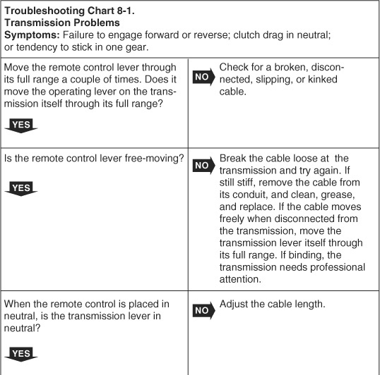
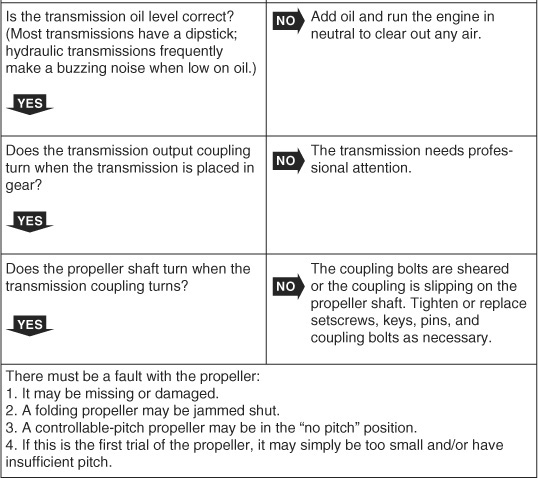
If the transmission operates stiffly, fails to go into either or both gears, stays in one gear, or slowly turns the propeller when in neutral (clutch drag), perform the following checks (Troubleshooting Chart 8-1):
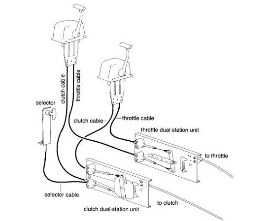
FIGURE 8-24. Typical remote engine and transmission controls comprising three sections: the cockpit or pilothouse control, the cable system, and the engine control unit. Top left: An enclosed cable-over-pulley system. Input motion is transmitted from the pilothouse control via the cables to the actuating mechanisms on the engine and transmission. Top right: A dual-station installation, with the main station using push-pull cables, and the remote station using a cable-over-pulley system. Bottom: A dual-station installation using remote bellcrank units and single-lever controls. On many modern boats, the cockpit control unit incorporates an electronic device that sends a signal to an operating unit at the engine and transmission (fly-by-wire). The only physical connection between the cockpit and engine is the data cable. (Courtesy Morse Controls, adapted by Jim Sollers)
• See that the transmission actuating lever (on the side of the transmission) is in the neutral position when the remote control lever (in the cockpit or wheelhouse) is in neutral (see Figures 8-25 and 8-26).
• Ensure that the actuating lever is moving fully forward and backward when the remote control is put into forward and reverse. This is particularly important on two-shaft transmission boxes—the travel should be an equal distance in both directions, without the operating lever snagging the transmission case at any point. It may be necessary to undo the clamp that holds the lever to its shaft and slide the lever out a little bit.
• Disconnect the cable at the transmission and double-check that the actuating lever on the box is clicking into forward, neutral, and reverse. Note: Two-shaft transmission boxes do not have a distinct click when a clutch is engaged. However, the lever must move through a minimum arc of 30 degrees in either direction. Less movement will cause the clutches to slip. More is OK. As the clutches wear, the lever must be free to travel farther (up to 45 degrees). If the transmission actuating lever is stiff, or not traveling far enough in either direction, make sure that it is not rubbing on the transmission housing or snagging any bolt heads (see above).
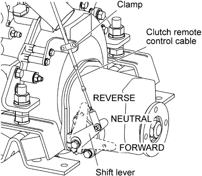
FIGURE 8-25. Check that the transmission shift lever is in neutral when the remote control is in neutral, and that the lever can move freely through a minimum of 30 degrees in either direction. (Courtesy Yanmar)
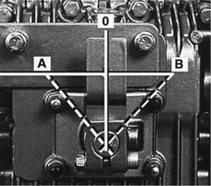
FIGURE 8-26. Clutch adjustment for many Volvo Penta transmissions. The travel of the control arm from 0 to A and from 0 to B must be equal. When the control cable has traveled no more than 1.2 inches (30 mm) in either direction, the relevant gear (forward or reverse) should be engaged. If the travel from 0 to A and 0 to B is not equal, adjust the position of the cover until it is as equal as possible. The travel increases in the direction in which the cover is moved. (Courtesy Volvo Penta)
• While the cable is loose, operate the remote control to see if the cable is stiff. If so, replace the cable. Note that forcing cables through too tight a radius when routing them from the control console to the engine is a frequent cause of problems.
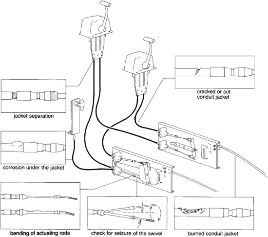
• Inspect the whole cable annually, checking for the following (see Figure 8-27):
a. seizure of the swivel at the transmission end of the cable conduit
b. bending of actuating rods
c. corrosion of the end fittings at either end
d. cracks or cuts in the conduit jacket
e. burned or melted spots
f. excessively tight curves or kinks (the minimum radius of any bend should be 8 inches)
FIGURE 8-27. Checking transmission control cables. (Courtesy Morse Controls, adapted by Jim Sollers)
g. separation of the conduit jacket from its end fittings
h. corrosion under the jacket (it will swell up; see Figure 8-28)
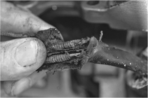
FIGURE 8-28. A corroded engine control jacket. The inner cable is stainless steel and is just fine, but the spiral-wound outer case is steel that has rusted right through.
If at all possible, remove the inner cable and grease it with a Teflon-based waterproof grease before replacing. Replace cables at least every five years and keep an old one as a spare.
If the oil is kept clean and topped off and the clutch or cables are properly adjusted, problems tend to be few and far between.
Heavily loaded transmissions, especially hydraulic transmissions, tend to get hot (too hot to touch). In fact, many that do not have an oil cooler would benefit from the addition of one. Excessively high temperatures, however, are likely to arise only if the oil level is low (a smaller quantity of oil has to dissipate the heat generated); the clutches are slipping (creating excessive friction); or an oil cooler is not operating properly.
A slipping clutch should be evident from a loss of performance. The intense heat generated will soon warp clutch plates and burn out clutch discs. The oil in the transmission will take on a characteristic black hue and may well smell burned.
Oil cooler problems may arise on the water and oil sides. Transmission oil generally remains pretty clean, but a slipping clutch and other problems occasionally create a sludge that can plug up the oil side of a cooler. And if the clutch is slipping, the oil will be darkened in color. If the cooler is raw-water cooled, a more likely scenario is that silt, corrosion, and scale are interfering with the heat transference on the water side. Note that some entry-level transmission coolers are nothing more than a box bolted to the outside of the transmission case with raw water circulating through the box—i.e., there are no heat exchanger tubes inside the cooler.
If the transmission has an oil cooler, the cooler is the most likely source of water, especially if it is a rawwater type. Pinholes form in cooler tubes just as in engine oil coolers. Regularly inspecting and changing sacrificial zinc anodes is essential. The only other likely source of water ingress is through the transmission output seal. For this to happen, the seal must be seriously defective and the bilges must have large amounts of water slopping around, both of which were far more common years ago when leather seals and wooden boats were the norm.
If you discover the water in a reasonable time and remove it, eliminate the source, and change the transmission oil a couple of times to flush the transmission, you stand a good chance of preventing any lasting damage.
The rupture of an external oil line will produce a sudden, major, and catastrophic loss of oil, which will immediately be obvious. Less obvious will be the loss of oil through a corroded oil cooler. If it is raw-water cooled, the oil will go overboard to form a slick; if freshwater cooled, it will rise to the top of the header tank (see page 142).
Although the seal around the clutch actuating lever or the seal on a hydraulically operated shaft brake occasionally leaks small quantities of oil, the most likely candidate for this kind of leak is the output-shaft oil seal. This is particularly true if the engine and propeller shaft are poorly aligned (which leads to excessive vibration), or if the propeller shaft has been allowed to freewheel when the boat is under sail. Alignment checks are covered in Chapter 9; seal replacement is dealt with below.
On rare occasions, the oil gets pumped through some ruptured seal into the flywheel housing.
With a two-shaft transmission, a delay in engagement when shifting into gear normally indicates wear in the thrust washers. The transmission should be professionally serviced before too long.
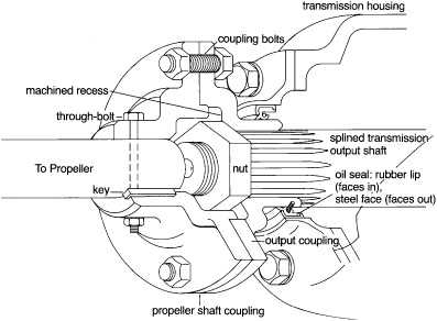
FIGURE 8-29. A transmission oil seal and output coupling arrangement. The recesses machined into the faces of the two coupling halves assist in shaft alignment. (Jim Sollers)
1. Unbolt and separate the two halves of the propeller coupling (see Figure 8-29). Mark both halves so you can bolt them back together in the same relationship to each other.
On some boats with vertical rudderposts, the propeller shaft cannot be pushed far enough aft to provide the necessary room to slide the transmission coupling off its shaft! The propeller hits the rudderstock and will go no farther. In this situation, remove the rudder or lift the engine off its mounts to provide the necessary space (this is an awful lot of work to change an oil seal; to avoid this problem in the future, you may want to consider having the propeller shaft shortened and installing a small stub shaft in-line between the transmission and propeller shaft).
2. Remove the coupling half attached to the transmission output shaft. This coupling is held in place with a central nut, which is done up tightly on most modern boxes; on some older boxes, it is just pinched up and locked in place with a cotter pin (split pin).
The coupling rides on either a splined shaft (one with lengthwise ridges all the way around) or a keyed shaft. (In the latter case, do not lose the key down in the bilges when removing the coupling!) The key will most likely stick in the shaft. If there is no risk of its falling out and getting lost, leave it there (tape it to the shaft for the time being); otherwise, hold a screwdriver against one end and tap gently until you can pry up the end and remove the key.
Some couplings are friction-fit on their shafts and should be removed with a proper puller (see Figure 8-30). This is nothing more than a flat metal bar bolted to the coupling and tapped to take a bolt in its center. The bolt screws down against the transmission output shaft, forcing off the coupling.
3. Transmission oil seals are press-fit into either a separate housing or the rear transmission housing. Most seals consist of a rubber-coated steel case with a flat face on the rear end and a rubber lip on the front end (the end inside the transmission). A spring inside the seal holds this lip against the coupling face to be sealed.
Removing a seal from its housing is not always easy. If at all possible, unbolt the housing from the transmission and take it to a convenient workbench. This is often fairly simple on older boxes and boxes with reduction gears, but may not be feasible on many modern hydraulic boxes. You may be able to dig out the seal with chisels, screwdrivers, steel hooks, or any other implement that comes to hand; it doesn’t matter if the seal gets chewed up as long as the housing and shaft (if still in place) are unscratched.
FIGURE 8-30. Removing an output shaft coupling with a simple coupling puller. (Courtesy Allison Transmission)
4. New seals go into the housing with the rubber lip facing into the gearbox and the flat face outside. Place the seal squarely in its housing and then tap it in evenly using a block of wood and a hammer. If you force the seal in cockeyed, it will be damaged. A block of wood is necessary to maintain an even pressure over the whole seal face— hitting a seal directly will distort it. Push in the seal until its rear end is flush with the face of the transmission housing. Once in place, some seals require greasing (there will be a grease fitting on the back of the gearbox), but most need no further attention.
5. Reassemble the coupling and propeller shaft by reversing the disassembly steps. Check the alignment of the propeller shaft (see Chapter 9) anytime the coupling halves are broken loose and reassembled.
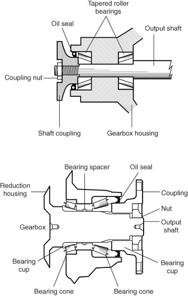
FIGURE 8-31. Top: A typical thrust bearing arrangement and location of the engine gearbox oil seal. Bottom: Preloaded thrust bearings. (Fritz Seegers)
Some transmissions have preloaded thrust bearings. The transmission output shaft, on which the coupling is mounted, turns in two sets of tapered roller bearings—one facing in each direction (see Figure 8-31). Between the two sets is a steel sleeve. When the coupling nut is pulled up, this sleeve is compressed, maintaining tension on the bearings and eliminating any play. Anytime the coupling nut is undone, use a torque wrench and note the pressure that is needed to break the nut loose. When reinstalling the nut, tighten it to the same torque plus 2 to 5 foot-pounds. In any event, the torque should be at least 160 footpounds on most BorgWarner boxes, but the couplings should still turn freely by hand in neutral with only minimal drag. If the transmission needs a new spacer between the thrust bearings, a special jig and procedure are necessary, and the whole transmission reduction gear will have to go to a professional.
On an older transmission in which the coupling nut is done up less tightly and restrained with a cotter pin, it is essential that you replace the nut properly. The best approach is to moderately tighten the nut, making sure everything is properly seated, then back it off an eighth of a turn or so before inserting the cotter pin. Put the transmission in neutral and turn the coupling by hand to ensure there is no binding. This type of coupling sometimes leaks oil between the shaft and the coupling; to prevent this, smear a little gasket sealer around the inside of the coupling before fitting it to the shaft.