Levers and linkages are some of the simplest machines and form the basis for countless more complex mechanisms. While levers are mostly used to provide a mechanical advantage that allows us to move heavy loads, linkages are mostly used to transform one type of a motion into another. Both are common in everyday life: If you have ever played on a seesaw or used pliers, you have relied on levers and linkages.
A basic lever is simply a beam that has one point of support in the form of a hinge or a pivot, as shown in Figure 7-1. We will call this point a fulcrum. A lever also has input and output forces. We will call the applied, or input, force the effort and the reaction force the load. Finally, we will call the sections of the lever between its fulcrum and its ends arms.
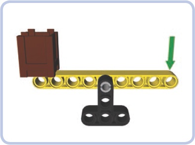
Figure 7-1. A simple lever, consisting of a beam (yellow) supported by the fulcrum (black). The brown crate is the load and the green arrow represents the effort. When effort is applied downward, the load is lifted up.
When a lever provides a mechanical advantage, our input force is amplified. But that increase in force does come at a cost, just as it does with all other simple machines. A lever with a mechanical advantage of 2 allows us to move the load using half the force it would take without the lever but covering only half the distance (traveling at half the speed).
The mechanical advantage of the lever depends on the distances between the fulcrum, the load, and the effort. The so-called law of the lever states that the mechanical advantage of a lever is equal to de/dl, where de is the distance between the effort and the fulcrum, and dl, is the distance between the load and the fulcrum. For example, for the lever shown in Figure 7-2, de (indicated by the blue arrow) is 5 studs long, and dl (indicated by the red arrow) is 3 studs long. Therefore, the mechanical advantage of this lever is 5/3, or 1.67. This means that in order to lift 1 kg of load 1 meter with this lever, we have to apply the effort needed to lift 0.6 kg and move the end of the lever 1.67 meters. The mechanical advantage still benefits us because we’re trading time, which we have plenty of, for force, which is limited.
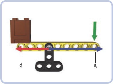
Figure 7-2. This lever has a mechanical advantage of 5/3, or 1.67, because the distance between the fulcrum and the effort is 5 studs and the distance between the fulcrum and the load is 3 studs.
The law of the lever also means that the force applied to the arm of a lever is inversely proportional to the arm’s length. Therefore, it takes more force to move a lever with a short arm than it takes to move a lever with a longer arm. A lever with a 3-stud-long arm will take twice the force as a lever with a 6-stud-long arm to move the same load. The lever with the 6-stud-long arm, though, will move the load twice as far because of its longer length.
Figure 7-3 illustrates the distance/force proportion. We have a lever with a 3-stud-long arm and a 7-stud-long arm. If we apply force to the longer arm, the lever offers a mechanical advantage of 2.33 (7/3), and if we apply force to the shorter arm, the lever offers a mechanical advantage of 0.43 (3/7). If we put a 1 kg load on the longer arm and a 2.33 kg load on the shorter arm, the loads will balance each other.
Note that a lever can have equal de and dl distances, resulting in a mechanical advantage of 1. This simply means that there is no mechanical advantage and the distance/force balance remains unaltered. Such a lever can still be useful, as it reverses the direction of movement (that is, by pushing down, you lift a load up).
Finally, note that a lever does not necessarily have to be a straight beam. It can be bent and work just the same. A simple crowbar is a good example of a bent lever (see Figure 7-4): It has a long arm, a short arm, and a central part that we put on the floor, thus creating a fulcrum. By shoving the short arm under the load, we are able to use the long arm to lift that load using less force than without the crowbar.
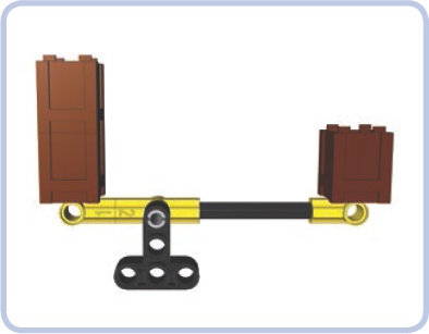
Figure 7-3. This lever has a mechanical advantage of 2.33, meaning that one of its arms is 2.33 times as long as the other one. Therefore, any load put on the longer arm can balance a 2.33 times heavier load on the shorter arm.
The positions of the fulcrum, the load, and the effort on a lever can vary. There are three possible combinations, which are called classes. Fortunately for us, the law of the lever is exactly the same for each class, meaning that the mechanical advantage is calculated in the same way for all of them.
The lever classes are as follows:
Class 1 (see Figure 7-5): The fulcrum is located in the middle of the lever and the load and effort at its ends. This is the only class of lever where effort and load are applied in opposite directions (that is, to lift a load up, you have to apply effort downward). Examples: a seesaw or a crowbar.
Class 2 (see Figure 7-6 and Figure 7-7): The load is located in the middle of the lever and the fulcrum and effort at its ends. Example: a wheelbarrow, with the wheel being its fulcrum.
Class 3 (see Figure 7-8 and Figure 7-9): The effort is located in the middle of the lever and the load and the fulcrum at its ends. Because of this arrangement, the class 3 levers have a mechanical advantage of less than 1 and are used to trade force for distance rather than the other way around. This makes them useful when there is plenty of force that can be used to move the load over greater distance. Example: a boom of a crane elevated by a pneumatic cylinder attached to its middle.
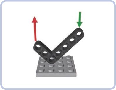
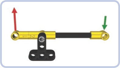
Figure 7-5. Class 1 lever with the fulcrum in the middle and the effort (green) and load (red) at its ends
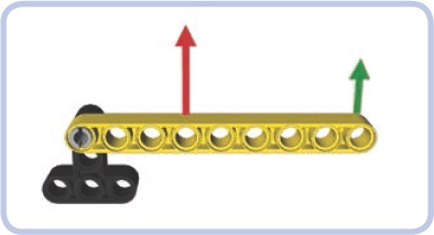
Figure 7-6. Class 2 lever with the load (red) in the middle and the fulcrum and effort (green) at its ends
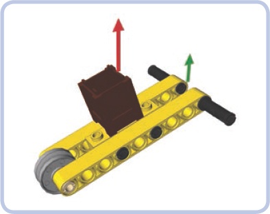
Figure 7-7. An ordinary wheelbarrow is an example of the class 2 lever, with its wheel being the fulcrum. The load is located in the middle of the wheelbarrow, and the effort is applied to the end of it. Wheelbarrows usually provide a mechanical advantage greater than 1, unless you apply the effort exactly where the load is located.
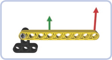
Figure 7-8. Class 3 lever with the effort (green) in the middle and the fulcrum and load (red) at its ends
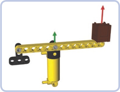
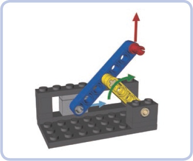
Figure 7-9. A boom of a crane is an example of the class 3 lever, with the load and the fulcrum at its ends and the effort applied to its center (in this case, by a pneumatic cylinder). Class 3 levers have a mechanical advantage less than 1, meaning that they require plenty of effort but can move loads over large distances. This is favorable when it comes to pneumatics, which can exert huge force but have limited reach.
An interesting thing happens when you connect ends of two identical levers located one above the other: The elements connecting their ends will maintain the same position as the levers move. This happens at every point in the levers’ range of movement, regardless of their length. We can use this system of parallel levers, also known as a 4-bar linkage, to our advantage.
As Figure 7-10 shows, we can expand our crane’s boom in Figure 7-9 by adding a parallel lever to it. This addition provides two advantages: First, we can move both levers by applying effort to only one of them because the elements connecting them will transfer the movement from one to the other. Second, and more importantly, the element at the “load” end of the levers will move with the levers while maintaining constant orientation. This means that the load’s angle won’t change as it moves up and down with the levers, which is useful when moving loads that we don’t want to tip over.
Many kinds of machines—front loaders and telescopic forklifts, for example—use parallel levers to handle loads. The LEGO 8265 set, shown in Figure 7-11, is an excellent example of a front loader: Its bucket is connected to arms that form parallel levers. Note that a linear actuator on each side acts as the lower lever, and by extending or retracting, it controls the bucket’s height. When it extends or retracts to the point that its length differs from that of the upper levers, an additional linkage between it and the bucket keeps the bucket level. The same additional linkage allows us to tip the bucket with another linear actuator. The bucket’s orientation depends entirely on the lengths and locations of the levers.
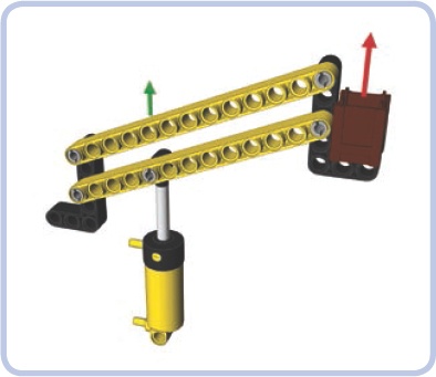
Figure 7-10. A boom of a crane made of parallel levers. The parallel levers ensure that the element on the end of the levers maintains constant orientation as the levers move it up and down.
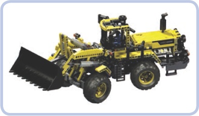
Figure 7-11. The LEGO 8265 set features a complex front loader whose arms (elevating the bucket) form parallel levers.
For the orientation to be maintained, the two levers have to be of identical length, and their ends have to be connected with identical spacing, as shown in Figure 7-12.
Note that the levers connected in this way can’t make a full rotation: They limit each other, colliding at a certain point. Therefore, their rotation is limited to a certain range, which can be adjusted by locating the levers not exactly one above the other but with a small displacement, as shown in Figure 7-13. Also note that the elements connecting the two ends of the levers don’t have to be identical, nor do they need to be set at the same angle—it’s only the angle and distance between the points of attachment that matter (see Figure 7-14).
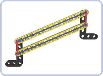
Figure 7-12. The parallel levers maintain the orientation of the elements at their ends only if the levers’ length and spacing are identical.
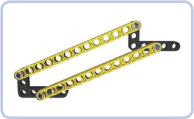
Figure 7-13. The parallel levers are displaced to adjust their range of movement. By moving the upper lever a little backward (left in the figure), we can increase the maximum reach upward at the cost of maximum reach downward.
Other variations are possible with a parallel-levers arrangement. For example, the element connecting the levers at the fulcrum can be rotated, making the element at the other end rotate at the same angle, as shown in Figure 7-15. This is one way to tip the bucket of our front loader.
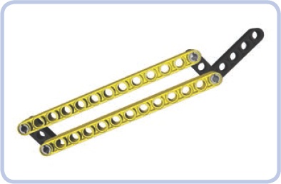
Figure 7-14. The functioning of the parallel levers relies on the positions of their points of attachment. These positions can be made identical on both ends using various elements set at various angles.
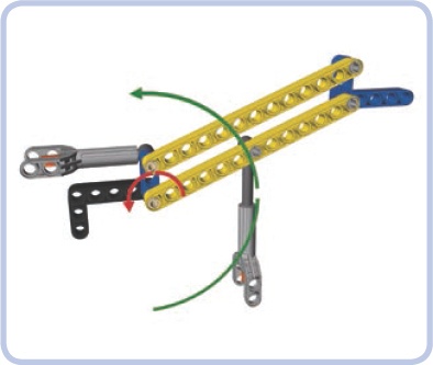
Figure 7-15. This boom variant uses one actuator to lower and raise the parallel levers (green arrow) and another to rotate the element that connects them at the fulcrum (red arrow), thus making the element at their other end rotate.
As Figure 7-16 shows, there is an interesting effect if the levers are not exactly parallel: Rotating the levers makes the element connecting their ends rotate slightly as well. This limits the levers’ range of movement but can sometimes be desirable—in particular, when we want the element at the levers’ end to be oriented differently in the lowermost and uppermost positions. This is the case with the LEGO 8460 Pneumatic Crane Truck set, where such an arrangement is used to control the stabilizing outriggers. This arrangement makes the outriggers nearly horizontal when lowered and nearly vertical when raised, effectively increasing their reach.
Finally, you can use the fact that the parallel levers rotate relative to the elements that connect them to your advantage. By putting gears on the axles that rotate together with the levers, we can transfer that rotation through these elements (for example, to another pair of parallel levers connected to it).
Figure 7-17 shows two pairs of parallel levers connected in such fashion—gears that transfer the rotation of one pair (left) to another (right). All the levers are identical and the gears maintain a 1:1 ratio, the result being that the element at the end of the series moves along a horizontal line. There is technically no limit to how many pairs of levers can be used in a series; the only constraint is the friction and the sum of the gears’ backlash.
Linkages are groups of rigid links connected by joints that allow them to perform certain restricted movements. They are mostly used to convert rotary or rocking motion into linear motion, allowing elements of various machines to move along straight lines. They can also be used to achieve mechanical advantage using the law of the lever. The lever is, in fact, the simplest linkage possible.
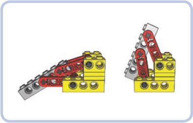
Figure 7-16. An outrigger mechanism from one of the LEGO mobile cranes uses levers that are not exactly parallel. The yellow part is the chassis, the levers are red, and the actual outrigger is grey.
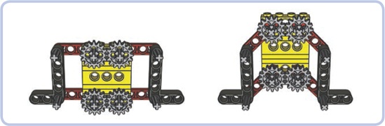
Figure 7-17. Two pairs of parallel levers connected by gears are installed on the element between them. The gears make the pairs rotate in opposite directions, moving the parts at both ends horizontally.
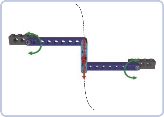
Figure 7-18. Watt’s linkage consists of two long side links and one shorter central link. A rocking movement of any of the side links makes the central link move so that its center (marked by the red pin) follows a straight line.
Note
In all the figures of linkages here, beams in the same color are of the same length. A dark grey color is used to mark the supporting structure, which remains stationary and to which the linkage is attached, and red pins mark the point of the linkage that performs the desired motion.
The key advantage of linkages is that their movement remains restricted without the need for external guiding elements, as shown in Figure 7-18. This makes them convenient for many uses. In the real world, linkages are used to control the movement of suspension components. Note also that usually only one particular point of a linkage follows the desired movement, and we can use pins located at this point to transfer this movement elsewhere—for example, to the base of the element we want to move using the linkage. A nearly infinite variation of motions can be achieved by varying the lengths and positions of just three or four beams!
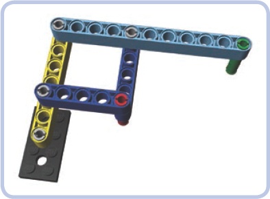
The Chebyshev linkage, also known as Tchebycheff’s linkage, consists of three links and is driven by the rocking motion of the lower links (light grey). This motion makes the central link (yellow) move so that its center (marked by the red pin) follows a straight line. The motion continues to the point at which the central link becomes vertical. The central link needs to be the shortest of the three to prevent it from colliding with the supporting structure (dark grey).

Hoeken’s linkage consists of three links and is driven by the rotary motion of the shortest one (yellow). The proportions of the following three dimensions are crucial to make this linkage work: the length of the shortest link (yellow), the length of the medium link (light grey), and the distance between points of attachment to the supporting structure. The proportions should be 2 to 5 to 4. The longest link (blue) can be extended to any length beyond its upper joint. The tip of this link traces the shape of a flattened oval cut in half (the dotted line in the illustration), and the size of this oval is determined by the extended link’s length. A little less than half of this link’s movement is linear. Such an unusual motion pattern can be used, for example, to drive the legs of walking vehicles.
A pantograph is a particular type of linkage with four links and two points, and its movement is quite interesting. In a pantograph, the point marked by the green pin mimics every movement of the point marked by the red pin, but on a larger scale. The difference in scale depends on the length of the longest link (light blue) and on where other links are attached to it (note that the longest link actually works like a lever).
The most interesting and popular use of this property is creating enlarged or reduced copies of drawings by attaching pens to both these points and “drawing” with one of them manually. This also works with handwriting; Thomas Jefferson used this method to duplicate his correspondence. Today, scaled copies can easily be created using a computer. However, pantographs still remain in use where certain tools require accurate manual control, as in engraving and sewing.
The Peaucellier–Lipkin cell, also known simply as Peaucellier’s cell, consists of seven links and is driven by the rocking motion of the central link (yellow). Note that the spacing between the cell’s two points of attachment to the supporting structure needs to be equal to the length of the central link.
The Peaucellier–Lipkin cell works on the principle of inversion of a circle (with the central link tracing part of it), and it was one of the first linkages capable of producing perfectly linear motion. Its invention was crucial for the development of 19th-century industry and, most notably, for its use in steam engines.
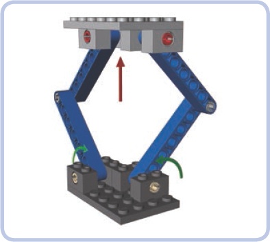
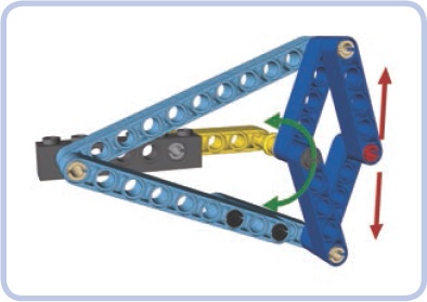
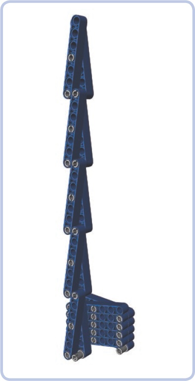
The Sarrus linkage consists of four links in two identical groups that are perpendicular to each other. All links are of equal length, and the linkage is driven by the rocking motion of both lower or both upper links. The advantage of the Sarrus linkage is that it can be used to lift the structure connecting the upper links, providing an impressive range of movement as seen in Figure 7-19). Note that the perpendicular links work in different directions and thus exert stress on each other, which is why they need to be very rigid and preferably several studs wide for the linkage to work properly.
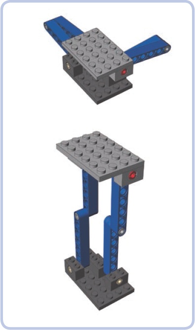
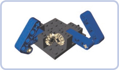
The disadvantage of the Sarrus linkage is that it requires one link from one group to be moved simultaneously with a second link from a second group. In other words, the motion of the links needs to be mechanically synchronized. Figure 7-20 shows one of the simplest synchronization methods. Note that the Sarrus linkage can consist of three or four groups as well, but two properly synchronized groups are enough to provide stable movement of the upper structure.
The Scott-Russell linkage consists of two links and is driven by the rocking motion of the shorter one (yellow). The longer link (blue) has one end attached to the supporting structure so that it can slide on it along a straight line. That makes the other end of that link move in a straight line as well. Both ends of that link move as if they were locked between guiding elements, but only one end actually is.
Note that the spacings between all joints of the linkage (marked by pins in the illustration) have to be equal. In this example, they are all equal to 3 studs.
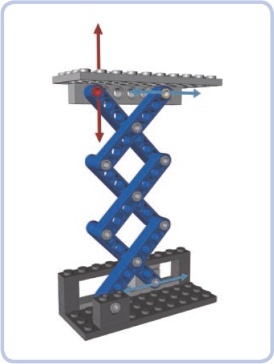
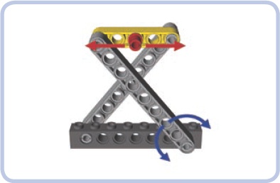
A scissor linkage, also known as a scissor mechanism, combines Scott-Russel and Sarrus linkages to create a compact mechanism capable of lifting with impressive range. It can consist of any even number of identical links—for example 2, 4, 6, and so on—and is driven by either the rocking motion of any link or by moving the end of the link that can slide within the supporting structure. Note that one of the top links also has an end that slides within the upper structure, but its movement can be restrained by simply making the upper structure’s weight rest on it. In the illustration, the end has an axle pin with a bush attached to support the upper structure while sliding.
The two key advantages of the scissor linkage, its range (shown in Figure 7-21) and its stability, combined with its compactness make it a very popular mechanical solution. For example, it appears in car doors to make windows move up and down; in so-called scissor lifts; and even in high-end computer keyboards, where it’s used to stabilize keys. There is no limit to how many links can be used in a scissor linkage, except that every joint adds extra friction. There are also no special length or distance requirements, except that all links have to be equal.
Watt’s linkage (shown earlier in Figure 7-18) consists of three links: a short central link (light blue) and two longer side links (blue). The linkage is driven by the rocking motion of either side link. As the side links rotate, the central links move so that the mechanism’s center follows the dotted line, which remains straight most of the time. Note that while the ends of that line deflect to the left and right, you can limit motion of the linkage to the straight part only.
Watt’s linkage is sometimes used in suspension systems to keep suspension components moving up and down rather than sideways. In most configurations, its side links are two or even three times longer than the central link.