The LEGO pneumatic system is a miniature model of real-life pneumatic and hydraulic systems. It consists of three basic modules: a pressure generator, such as a manual pump or a motorized compressor; a control module, one or more valves that direct the flow of air; and cylinders, which convert pressure to linear movement. The modules are connected by elastic pneumatic hoses.
The basic working principle of a pneumatic system is based on the tendency of air to move from areas of high pressure to areas of low pressure. The pressure generator fills the pneumatic system with pressurized air, and then the air is directed to the cylinders using the control module, which makes the cylinders extend or retract. When the pressure of the system is equalized, all movement stops.
Every pneumatic system has limited capacity for air pressure. In the case of LEGO models, that limit is normally three bars, which is roughly equivalent to three times atmospheric pressure. If a LEGO pressure generator exceeds this capacity, the pneumatic hoses may pop off the ports of pneumatic pieces.
Because the LEGO pneumatic system relies on hoses and connectors, it is not perfectly closed and is subject to microleaks. Microleaks, small amounts of air leaking out of the pneumatic system, usually occur at the ends of pneumatic hoses (or in the middle if they are damaged). These microleaks result in reduced efficiency. And of course, as with any mechanical system, complexity is the enemy of efficiency in pneumatics.
Note
Although LEGO connectors in the pneumatic system are technically called inlets and outlets, I’ll call them ports for the sake of simplicity.
There are actually two different LEGO pneumatic systems: Old and New. Each works a bit differently, as described in the next sections.
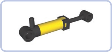
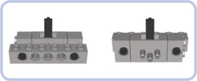
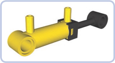
Introduced in 1984, the Old LEGO pneumatic system (shown in Figure 9-1) is relatively complex. Its control module includes two interconnected pieces and one pneumatic hose that connects the pressure generator to the cylinders. Although the last LEGO set that included the Old system was released in 1987, this durable system continues to be widely available.
The pump shown in red at  usually has a spring. When pushed, it pumps the surrounding air through its port, and the spring returns the pump to its initial rest position when released.
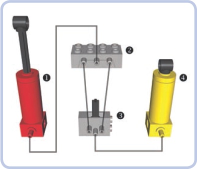
Figure 9-1. The Old-style pneumatic system uses two blocks to control airflow. The grey lines in this diagram represent hoses.
The light-grey element at  is a distribution block, which includes a special one-way valve. Air is delivered from the pump into the distribution block’s middle port, and the one-way valve forces the two side ports to pump air in only one direction: The port on the left takes air in, and port on the right expels the air. Thanks to the distribution block, we can not only increase the pressure in the LEGO pneumatic system but also decrease it by expelling air from the system.
The light-grey element at  is a valve, which is connected to the distribution block by two hoses. A single distribution block can be connected to many valves using forked hoses. The total number of valves depends on how many pneumatic cylinders are meant to be controlled independently.
The valve has a lever that can be switched to one of three positions. One position extends all connected cylinders, another retracts the cylinders, and the third (middle) position cuts the connection that goes through the valve, effectively locking all cylinders. This third position is called neutral, and it is needed when you have many valves in a system because it prevents the valves from interfering with each other. Additionally, with the valve in neutral, the pressurized air remains sealed and thus can be used more efficiently in other parts of the system.
The yellow element at  is a cylinder, which extends when air is delivered to it and retracts when air is sucked from it.
Note
When a cylinder is subjected to suction, the air pressure inside it drops until it becomes lower than the atmospheric pressure surrounding it (one bar), at which point the cylinder starts to retract. For this reason, the LEGO pneumatic system can exert up to three bars of pressure for extension, but only up to one bar of pressure for retraction.
Compared with the New pneumatic system (discussed below) the Old pneumatic system does offer one advantage: It requires only one hose to connect a cylinder to a valve. But it also has several disadvantages. One is that it applies much less force to retract a cylinder than it does to extend it because air is expelled from the cylinder during extension and drawn in during retraction. Since the force exerted by the cylinders in a pneumatic system depends on whether they extend or retract, this is often considered a significant disadvantage, and this disadvantage is one of the main reasons why the New system was created.
Also, the control module in the Old system is complex, requiring two hoses for every valve connected to the distribution block. Finally, the Old system has many unique pieces (the pump, distribution block, and cylinders) that haven’t been produced since 1987, making it virtually obsolete.
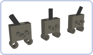
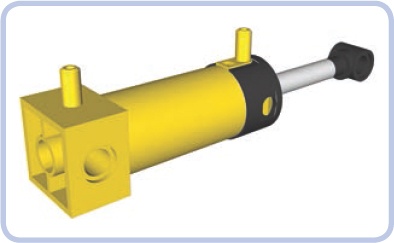
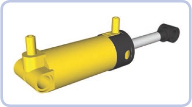
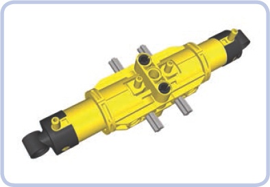
LEGO introduced the New pneumatic system (shown in Figure 9-2) in 1989 with the goal of simplicity and efficiency. The New system eliminated the distribution block and redesigned the pumps and cylinders, though it does use the Old valves. This new system is much more like real pneumatic and hydraulic systems.
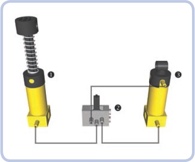
The yellow element at in Figure 9-2 is a pump that works only with the New system. The light-grey valve at is the same as that in the Old system except that it is connected a bit differently: Air is delivered into it through the middle port, and its side ports are connected to the cylinder. Either valve’s port can be connected to either cylinder’s port; this connection determines which of the valve’s two extreme positions makes the cylinder extend or retract.
The yellow element at is a cylinder. It extends or retracts depending on which port the air is delivered to.
Unlike the Old system, the New one expels air through the valves, resulting in distinctive hissing sounds when valves are switched under high pressure. Also, because the New system doesn’t use suction, retraction is only slightly weaker than extension.
Note
You can swap the cylinders between the Old and New systems, but the cylinders from the Old system will perform poorly due to their different internal construction.
Compared with the Old system, the New system offers the advantage of using a simple control module, and the same force is exerted by the cylinders regardless of whether they extend or retract. Its main drawback is that two hoses are required for every cylinder connected to the valve, which can make multicylinder pneumatic systems very complex.
The New pneumatic system is used by most LEGO builders today, though some choose the Old system in order to reduce the number of hoses needed to connect cylinders or simply because they prefer the red cylinders.
Although the principles of the New system haven’t changed since 1989, some new pieces have been added and existing pieces have been updated.
This section describes all existing pneumatic pieces, in order of function, from pressure generators, control modules, and cylinders to miscellaneous pieces. Since most of the pieces in the New and Old systems are interchangeable, I’ve listed them together.
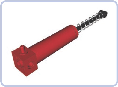
This is a large manual pump with a single port and a spring-loaded rod. It comes in two lengths and in both red and yellow. It draws air in from the outside when the rod is pushed; when the rod is released, the spring returns the pump to its initial, neutral position.
The pump’s bottom can be mounted on studs, and both its ends have regular Technic holes. The lower end (the one with the port) is 2 studs wide, and the upper end is 1 stud wide. The pump’s upper end makes manual pumping uncomfortable: When pumping fast for a prolonged time, it quickly becomes hot due to the compression of the air inside it.
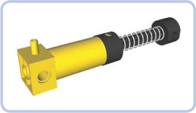
This is the large manual pump from the New system. This part is always yellow in LEGO Technic sets and transparent light blue in LEGO Education sets.
Like the Old system’s pump, it contains one port and a spring-loaded rod. It works just as the old pump does, and its dimensions are almost identical, except for the addition of a contact pad on its upper end. This contact pad is designed to make manual pumping much more comfortable, and it does, but the pump is still prone to heating up just like the Old one.
This small pump with one port has a rod that extends by 2 studs and no spring. It is best used with motorized compressors rather than manual pumps. Because it’s so much smaller than the other pumps, it takes longer to provide comparable pressure, which is why compressors often include more than one such pump. It is also much less prone to heating.
This pump comes in yellow, blue, and a transparent light blue. In 2011, a new version was released with the 8110 set; it’s light grey and is half a stud longer, resulting in slightly increased capacity.
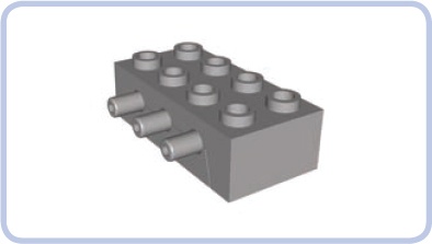
The distribution block is a light grey piece that’s the same size as a 2×4×1 LEGO brick. It is used exclusively in the Old pneumatic system for sucking air out of the cylinders and hasn’t been produced since 1987. It has three ports on one side, and air is delivered to the middle one. A one-way valve inside affects how the ports work: The middle port allows air to flow both ways, the left allows air to flow in only, and the right allows air to flow out. If you use the ports incorrectly, the valve will close, stopping all air circulation inside the block. The valve will reopen once you connect the ports properly.
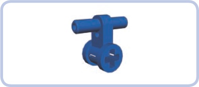
The valve is the size of two 1×2 bricks and a 1×2 plate stacked, and it is always light grey. It has three ports on one side, with air delivered to the middle one.
A lever (roughly 1.5 studs long) on one of the valve’s narrow sides can be switched to one of three positions. The middle position, called neutral, cuts the connection inside the valve, effectively disconnecting the side ports from the rest of the pneumatic system. The top and bottom positions control the flow of air through the valve’s side ports, as shown in Figure 9-3, making cylinders connected to these ports extend or retract. (The valve does not actively take in air; it only receives air through its ports and expels it through the hole that houses the switch.)
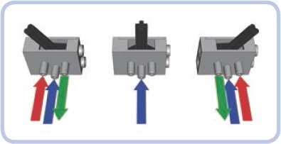
Figure 9-3. The direction of airflow through the valve’s ports: Blue arrows show air coming from the pump, green indicates air coming out from the valve to the cylinder, and red indicates air returning from the cylinder to the valve.
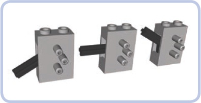
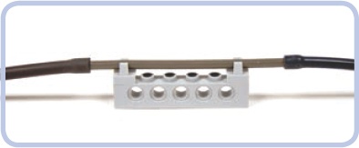
A valve can be attached on the top or bottom of any studded LEGO piece. It can also be mounted between two 1×2 Technic bricks, which can then be connected with pins to any piece that has at least five pin holes (see Figure 9-4).
Introduced in 2003, this New valve works the same as the valve with studs. Unlike the Old valve, it comes in dark grey, but it has similar dimensions. Aside from the color, the only difference is its lack of studs and the addition of two pin holes, 1 stud apart, at one side of the valve. These changes make it better suited for studless constructions. Also, because the valve’s points of attachment are on one side and the valve’s lever is on the other, the lever remains conveniently exposed when the valve is attached to something.
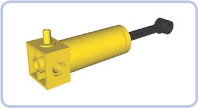
This cylinder from the Old system, which hasn’t been produced since 1987. It includes a single port and a plastic rod that extends by nearly 4 studs. Available in yellow and red, its dimensions are the same as those of the Old large pump. Unlike the Old pump, however, it has no spring. The cylinder’s upper part expels air when extending and draws it in from the outside when retracting, and the cylinder exerts more force when extending than it does when retracting. It’s only partially useful with the New pneumatic system because it can be extended but not retracted.
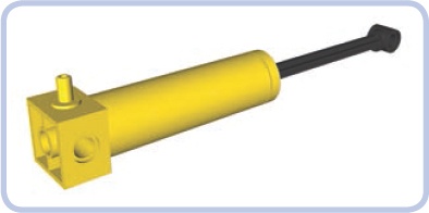
This yellow cylinder is basically just a longer version of the Old system’s large cylinder. It has a single port and a plastic rod that extends 6 studs, and it has no counterpart in the New pneumatic system; in fact, it is the only pneumatic cylinder this long. Its plastic rod and long reach make it more likely to break under stress than any other cylinder.
As with all Old-style cylinders, its upper part expels air when extending and draws it from the outside when retracting, and it exerts more force when extending than when retracting. And, just as with the regular large cylinder, its usefulness in the New system is limited because the New system doesn’t allow it to retract.
The New system’s small cylinder has two ports and a plastic rod extending 2 studs. In the Technic sets, it’s always yellow, though it comes in a transparent light blue in the Education sets.
This rare and expensive pneumatic piece is easily confused with the small pneumatic pump. This piece is unable to exert large force due to its small capacity, but it’s valued for its small size. As with all cylinders in the New system, it is completely airtight.
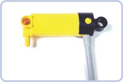
The New system’s large cylinder is one of the most common pneumatic pieces. It has two ports and a metal rod extending by nearly 4 studs that makes it very robust. It is similar in size to the large pneumatic pump.
This updated version of the large cylinder, introduced in 2002, has two ports and a metal rod extending by nearly 4 studs. The only difference between this cylinder and the Old one is that it has a round rather than a square base; the round base takes up less space and cannot be mounted on studs. However, the rounded design allows the New cylinder to tilt in tight spaces, which has made it very popular.
The square, Old version of this pump requires a large margin of free space around its lower end in order for the cylinder to tilt, which makes it less realistic. Real hydraulic cylinders are almost always mounted on a pin joint so that they can pivot during their stroke, which prevents loads from bending the actuator. The round base on the New cylinder allows for this type of action, making it more realistic than the square version.
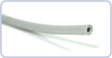
The 4 mm thick elastic rubber hose is a vital part of the Technic pneumatic system. It comes in various lengths and colors—black, grey, and blue—and is easy to insert through Technic holes and connect to ports of the pneumatic system.
When working with hose, remember that LEGO pneumatic systems cannot maintain high air pressure for prolonged periods and each hose leaks somewhat, so the system becomes increasingly inefficient with each hose you add. Additionally, hoses tend to pop off ports when the pressure exceeds three bars, and if a hose is stretched or damaged, it can pop off even below three bars. The oldest hoses, rarely found today, were made of a material that slowly broke down when exposed to UV light, causing them to develop cracks and leaks. The newer hoses are made of silicone and are mostly immune to these problems.
The 4 mm hoses make it easy to circulate air through any pneumatic system, no matter how complex, and they take up very little space in LEGO constructions. Their flexibility and resilience allows them to span components that need to have relative motion, but their inner ducts are narrow and can easily become blocked. To avoid blocking the tubes, be sure that the surrounding structures do not press on a hose and that no hose is stretched or bent sharply.
Figure 9-5 shows a pneumatic hose connected to the upper port of a (New) large cylinder. Note that when a hose is attached to a port, it becomes thicker than 1 stud. As a result, the part of the hose with the port inside it can’t fit through a Technic hole.
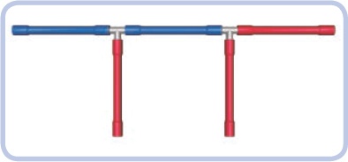
In addition to ports, pneumatic hoses can also be connected to 3 mm thick rigid tubes in order to join several pneumatic hoses to create longer ones.
In real hydraulic and pneumatic systems, hose is always used to describe a flexible part, and tube is used to describe a rigid part. In keeping with this terminology, I’ll refer to the flexible silicone parts as hoses and the 3 mm rigid parts as tubes. Figure 9-6 shows how a 3 mm tube can connect two pneumatic hoses. But these tubes can also be connected to any studded structure, such as a brick, in a way that would not be possible with the regular pneumatic hose.
Note
Real machines equipped with pneumatic or hydraulic systems often use rigid tubes to traverse structures that do not bend, such as the boom of a crane. The 3 mm tube makes this type of construction easy to model with LEGO pieces.
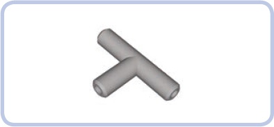
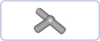
The Old version of the T-piece, which hasn’t been produced since 1996, is simply a small, T-shaped piece with three ports. When air is forced into one port, it flows into the two other ports, making the T-piece work as a pneumatic parallel connector.
T-pieces are used to divide pneumatic hoses in two by connecting a hose to each port (see Figure 9-7). Two of the hoses act as a single section with the T-piece in the middle, and the third one acts as its branch. Because every T-piece adds one new branch to a pneumatic hose, in order to split a hose into four, you need three T-pieces: one to split the hose in two, and two more to split each of the two resulting hoses into two again. The rule is a universal one: splitting a single hose into n hoses requires (n − 1) T-pieces.
Note
Splitting hoses lowers the effectiveness of the whole pneumatic system because changing the direction of airflow by 90 degrees produces drag.
The updated version of the T-piece has a ball-shaped center, which makes it easier to disconnect from hoses. It works the same as the Old T-piece, but it is stronger and slightly more effective in reducing drag. T-pieces are always light grey.
This piece was introduced with the 8110 set in 2011. It looks a bit like the T-piece, but instead of splitting hoses, it’s used to extend them.
Designed to connect two sections of pneumatic hose in a way that makes the hoses easy to remove, this piece allows you to easily connect or disconnect two pneumatic systems. Due to its design, this piece is especially handy for creating pneumatic power take-off (PTO), a connection that powers external attachments like a pneumatic snowplow or a knuckleboom crane, as in the original 8110 set. Many agricultural machines also come with PTOs; for example, a tractor might swap between different attachments.
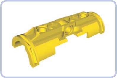
The new pneumatic system doesn’t include 6L cylinders, and the regular large cylinders, which have nearly 4 studs of extension range, are too short for certain purposes. The solution is to join two cylinders with the bracket shown in Figure 9-8 so that they work like one cylinder with rods extending from both ends, effectively doubling both the length and extension range.
The brackets are symmetrical, so you can have one cylinder with ports facing up and the other with ports facing down, but having all ports on one side will make it easier to connect hoses.
Note
For the cylinders to work as one, you have to couple their lower and upper ports separately with hoses forked using T-pieces.
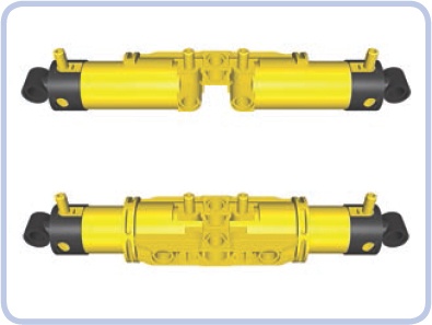
Figure 9-9 shows two brackets secured around two cylinders by two axles and two 3L beams with pins. The brackets are not physically attached to the cylinders or to each other. To attach them, either insert axles through their axle holes or add pins to their central holes and connect them with 3L beams. The pins-and-beams method is more reliable because it prevents the brackets from coming apart; however, it uses the brackets’ central holes, which are often better used for routing hoses.
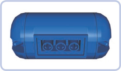
The airtank stores compressed air. This part is blue in Technic and white in the Education system. It comes in handy particularly when you want to create a pneumatic system that doesn’t require constant pumping. While with a little tinkering you can connect pneumatic hoses to plastic bottles or bags to store air, the airtank is the only original LEGO piece designed for this purpose.
Note
Each pneumatic system has a capacity equal to the volume that can be filled with pressurized air. This volume is typically related to hoses: Adding several long hoses adds to the capacity significantly. The airtank’s capacity, however, is far greater than that of any number of hoses.
To have the air stored in the airtank available for the whole pneumatic system, place the airtank between the pressure supply and the control module.
According to LEGO, it takes 30 to 35 repetitions with a large pneumatic pump to fill the airtank completely. At roughly 40 repetitions, the pressure will reach the critical three bars, causing either the pump to stop working or the hoses to pop off its ports. (If a breach occurs, the pressurized air will escape the airtank in a split second.)
Despite its apparent simplicity, the airtank’s shape is actually quite complex. Its bottom has a 2×4 connecting area that can be used with any bricks or plates. To attach it to anything larger than a 2×4 piece, try adding a 2×4 plate as a buffer (see Figure 9-10).
The airtank’s connecting area also includes three 1-stud-deep axle holes, which you can use to mount the airtank on axles or axle pins. You can do the same with the single axle hole above each of the airtank’s ports.
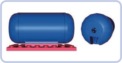
Figure 9-10. Because of the shape of the airtank’s bottom, a spacing of at least a single plate is required to connect it to anything larger than a 2×4-stud area. A 2×4 plate is used here. Note that despite the presence of the large red plate, it’s still possible to connect hoses to this airtank, thanks to its angled ports.
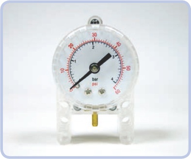
The manometer was released in 2008. It is designed to measure the air pressure in a pneumatic system in both pounds per square inch (psi) and bar units. It is enclosed in a semitransparent 5×8×3 case, with a single metal port at the bottom.
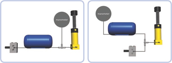
To use the manometer to measure air pressure in the pneumatic system, place it between the pressure supply and the control module. It can be connected with a single section of pneumatic hose to practically anything, whether that’s the airtank or any two sections of a hose using the T-piece. Figure 9-11 shows two examples of manometer placement.
The manometer’s usefulness is limited. If you choose to use it, remember that it is best used with the airtank. If you choose to use the manometer on a pneumatic system without an airtank, its readings will change drastically with each movement of a pump or valve.
The pneumatic system is ripe for experimentation. Here are some common ways to tinker with it.
It’s easy to replace the original LEGO pneumatic hoses with custom ones, as long as the custom hose is elastic and 4 mm thick (if you want to be able to insert it through Technic holes) and as long as it has reasonably large inner ducts. Some industrial hoses may come in handy for this purpose—for example, the fuel hoses used for radio-controlled models. Medical drip hoses—that is, IV lines—can be used too, but they tend to be sticky and to collect massive amounts of dust.
Although the LEGO airtank is quite useful, you can replace it with practically any airtight container. Plastic bottles or bags and even balloons can work very well as long as you connect them to the pneumatic system in a way that keeps them airtight.
Since the large pneumatic pumps are so much more powerful than the small ones, they can be used to advantage in motorized compressors. The one problem you’ll encounter is that the spring in the large pump resists the force of the compressor’s motor and slows the entire mechanism down. To solve this problem, remove the spring by pulling it off the Old large pump or, with the New pump, cutting it (because the contact pad gets in the way).
In heavy models, you can use the large pneumatic cylinders instead of shock absorbers to create a kind of pneumatic suspension. Depending on the pressure of the air inside them, the cylinders will tend to retract under the load and extend back to their neutral position once the load is reduced or gone.
The advantage of pneumatic suspensions is that they’re tough and they allow you to adjust ground clearance simply by changing the air pressure. But they also have a few disadvantages: Their performance is worse than that of traditional shock absorbers, they’re best used with heavy models, and their pneumatic system needs to be refilled from time to time due to microleaks.
In real life, pneumatic systems are less popular than hydraulic ones. Liquid-filled hydraulic systems are widely used by machines that handle heavy loads, especially construction equipment like excavators, cranes, front-end loaders, backhoes, skid-steer loaders, forklifts, dump trucks, and so on.
If your constructions need to handle heavier loads, you can turn the pneumatic system into a hydraulic one by replacing the air with liquid, although this has to be done carefully. Liquids are much denser than air and much less prone to compression.
Of course, there are certain risks in filling the LEGO pneumatic system with fluid, the most important of which is that you may damage large cylinders: They have metal rods, which can corrode depending on the fluid you use. Also, the rods are covered with grease for lubrication, which may react with the fluid you choose or be removed by it. And even if you use a “safe” fluid, there is still the matter of drying the cylinder after use—a difficult task given that the cylinder is almost fully closed.
The following is a list of tips for using fluids in LEGO pneumatic systems. I’m not recommending that you fill the system with fluid, and if you do so, you may damage your pieces in the process. Remember that if you decide to experiment with fluids, you do so at your own risk. Be advised that when things go wrong, it can get pretty messy!
The best choice of liquid is a mineral oil—a noncorrosive, nonreactive, odorless fluid that is safe for human contact. Mineral oil is 20 percent thinner than water, inexpensive, and available at most drug stores.
You should only convert the New LEGO pneumatic system to hydraulics because the valve is the only exhaust in the system; the fluid will exit only from there instead of exiting from cylinders, as in the Old system.
You’ll need a constant supply of fluid, and the LEGO pumps must be fully submerged in the fluid in order to pump it.
The fluid’s viscosity will improve the way the cylinders handle heavy loads, but this also means that you will need to apply much greater force while pumping.
The integrity of the seals in the pneumatic system is very important when fluid is used. Any leaks can introduce air into the system, which could block its function completely.
Any leak in a fluid-filled pneumatic system can affect its surroundings. Make sure that there are no electric or metal pieces near the pneumatic system in your construction. Also, try to build the system so that if a hose pops off, you can access the hose quickly and block it or lift its end to stop the fluid from leaking out.
Never use the manometer with fluids; you’re likely to damage it permanently.
It’s very difficult to dry the insides of pneumatic pieces unless you disassemble them. Pumping warm air through them continuously for a prolonged period of time will help; you can also try leaving them for a while in a bag of uncooked rice, as rice absorbs moisture.