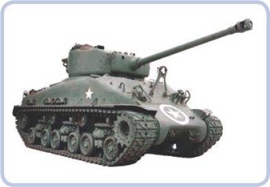
Tracked vehicles are superior to wheeled vehicles for covering rough terrain. In a manner of speaking, tracks allow tanks and construction vehicles to “carry their own road” wherever they go. To create tracked LEGO vehicles, we have two options: rubber tracks and hard plastic tracks, each with a different set of advantages.
LEGO’s rubber tracks are made of a single, solid loop of rubber. LEGO produced seven rubber track variants, three of which are obsolete and difficult to find. The remaining four are quite similar to each other, and one variant dominates in terms of popularity (see Figure 16-1).
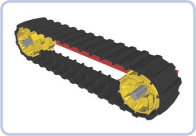
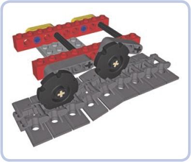
This track has 34 segments and is a little less than 3 studs wide. With its deep tread, the rubber provides excellent traction. The loop must be driven with a special type of sprocket wheel called a tread hub; the track requires two hubs 13 studs apart to be fully stretched, as shown in Figure 16-1. Tread hubs have a diameter of 3 studs, and their width is just a little bit less. They come in a variety of colors, and they use pin holes. In order to make your sprocket gears rotate with an axle, you must lock them with 16-tooth gears, as shown in Figure 16-2. You’ll need two 16-tooth gears per hub—one on each side—or, to save space, you can use a single gear on one side and a bush on the other.
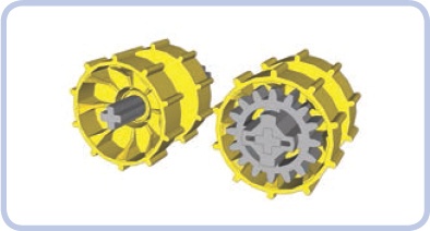
Figure 16-2. Two tread hubs: one empty (left) and one with a 16-tooth gear inserted (right). Since the hub is less than 3 studs wide, the gear sticks out slightly.
Advantages of rubber tracks:
They are a single, unbreakable loop.
They provide superb traction.
They create minimal noise when driving.
Disadvantages of rubber tracks:
Their length is limited and fixed.
Their sprocket wheels are available in only one size.
Rubber becomes less and less elastic over time.
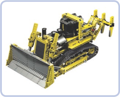
Hard plastic tracks (also known as solid tracks) are individual plastic links connected with one another. Their length can be easily adjusted, and they come in two versions: an older (and smaller) one and a newer (and bigger) one, both shown in Figure 16-3. Figure 16-4 shows a vehicle using the new plastic track type.
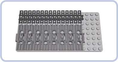
Neither type of hard plastic track measures a whole number of studs in width. Instead, the tracks are slightly narrower, which prevents them from abrading the structure around them as they rotate. The older tread type is slightly less than 3 studs wide, and the newer one is slightly less than 5 studs wide. The length of tracks is a little difficult to compare, as no link is an equal number of studs long either; however, a 15-link-long section of older track is equal to an 8-link-long section of new track, and those lengths are both equal to 13 studs, as shown in Figure 16-3. A single link of the newer type is thus equal to 1.875 links of the older type. A link of the new track is 1.625 studs long, while the older link is 0.867 studs long.
The older tracks come primarily in black, and they are similar in construction to LEGO chains, as you can see from their links in Figure 16-5. This means that any gear that works well with a chain can be our sprocket wheel for a tracked vehicle. As shown in Figure 16-6, a single link occupies two teeth on a gear.
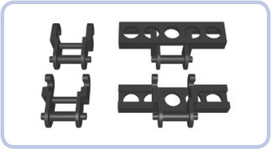
Figure 16-5. Regular LEGO chain links (left) and older-type track links (right). The older track links are just modified chain links.
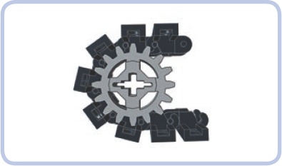
Five types of gears can be used as sprocket wheels for the older tracks (see Figure 6-5 in chains). Other gears just aren’t suitable because of the shape of their teeth or simply because of their small diameter.
The small openings in the older tracks can hold a plate, a tile (as shown in Figure 16-7), or even a brick that is at least 4 studs long. While bricks aren’t typically used because they fall off too easily, plates and tiles can make the tracks wider and improve their appearance.
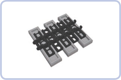
Figure 16-7. A section of older track with tiles added. Note that only every other link can have a piece inserted into it.
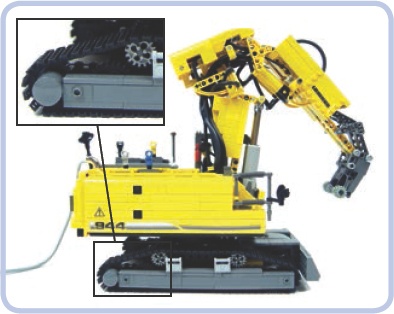
Figure 16-8 shows my model of a Liebherr R944C excavator, which combined two types of gears to keep the tracks in place. I used 24-tooth gears at the ends of the tracks and 16-tooth gears to give shape to the tracks’ upper sections.
The newer tracks are made of massive links that come primarily in dark grey; black and metallic silver versions are available as well. Each link comes with two pin holes, which allow for modification (see Figure 16-9).
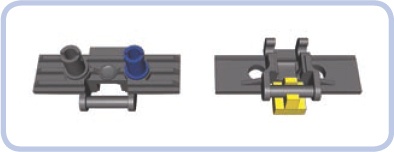
The new solid tracks can’t be driven by regular Technic gears; instead, they use special sprocket wheels. There are two options: a big wheel and a small one (both shown in Figure 16-10). The big sprocket wheel can have up to 10 links wrapped around it, is almost 2 studs thick, and comes primarily in yellow, with orange and black available, too. The small one can have up to 6 links wrapped around it, is 1 stud thick, and comes in black and pearl grey.

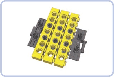
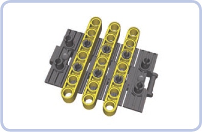
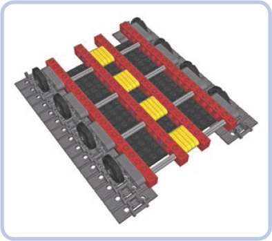
The pin holes on top of the newer links can be used to attach Technic bricks (as shown in Figure 16-11) or beams (as shown in Figure 16-12) to them, making them wider and suitable for driving in snow. Both bricks and beams can be attached to every link using two half or three-quarter pins, with the latter ones being less likely to fall off. It is also possible to weave a regular rubber band into the pin holes, improving the traction of the tracks and reducing the noise they create while driving.
The two solid track types differ in how much they can be stretched; the older type is more elastic but, at the same time, more fragile and prone to break. The newer type is much sturdier but very rigid, and as a result, it’s difficult to obtain optimum tension with it. If your tread is too loose or too tight, it will affect how a vehicle drives. The rule of the thumb is to tighten it as much as possible and then give it at least half of a link of play.
Advantages of solid tracks:
Disadvantages of solid tracks:
They have poor traction.
They’re prone to coming apart (especially the older type).
It’s difficult to obtain optimum tension (especially with the newer type).
They’re noisy while driving (especially the newer type).
Tracks greatly improve a vehicle’s off-road performance, especially on mud, snow, or other unreliable surfaces. But how well a vehicle moves on its tracks depends largely on its wheels.
Strange as it may seem, wheels are no less important for tracked vehicles than they are for a car or truck. Firstly, they provide power to the tracks and keep them from falling off. Secondly, they can be suspended in order to improve the flotation of the vehicle, which describes how well the suspension handles obstacles. A suspension that adapts well to rough terrain provides good flotation, reducing the shock transferred to the vehicle as it moves.
Note
The first tanks ever built provide a good example of just how important suspension is. Because these tanks lacked any kind of suspension, the crewmen of such tanks would often be knocked unconscious by shocks while traversing trenches.
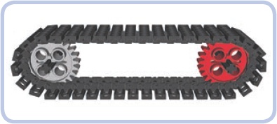
Let’s discuss the basic wheel systems. The simplest wheel system consists of two sprocket wheels per track, as shown in Figure 16-13. Usually about half of such a wheel comes in contact with the track, more than any other wheel in the system—which is why it’s important that these wheels are those that drive the tracks. Usually only one sprocket wheel is actually driven, and it’s often the rear one because it’s convenient to have propulsion systems at the back of the vehicle. But it doesn’t really matter which sprocket wheel is driven, as the track works like a chain and transfers the drive to the other wheel.
The second function of the sprocket wheels is to maintain the track’s tension, which is particularly important as the vehicle moves over obstacles. Sprocket wheels can be suspended on an elastic element to maintain this tension. A loss of tension can cause the track to slip or even separate.
But with the basic two-wheel-per-track system, it would be difficult to add any suspension. We could suspend the nondriven sprocket relatively easily, but suspending the driven one would be much more challenging. This is why road wheels were invented.
A more advanced wheel system includes road wheels at the bottom of the vehicle (shown in blue in Figure 16-14). Road wheels can be used in any number, they are not driven, and they can be easily suspended. They are usually located closer to the ground than sprocket wheels, and they support the weight of the vehicle. Some vehicles come with sprocket and road wheels on the same level, making the road wheels difficult to suspend but increasing the total area of contact between the track and the terrain. Real tracked vehicles have been built both with many small road wheels (as shown in Figure 16-15) or with a few big ones. As a kind of compromise between the two extremes, modern tanks usually have six or seven road wheels per track that are just over half as big as the sprocket wheels.
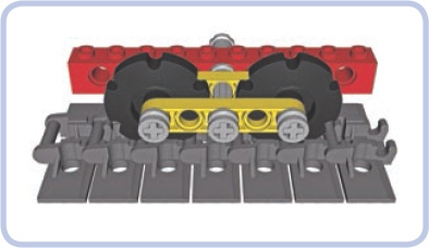
The most complex wheel systems also include return rollers (shown in yellow in Figure 16-16). They are neither driven nor suspended, and their only function is to support the upper portion of the track. Return rollers can have minimal contact with the track and, in fact, don’t even have to rotate—it’s enough if the track can slide over them. As tracks are always more or less loose, vehicles with long tracks usually need at least two return rollers. It is also possible to use road wheels large enough to function as return rollers, as shown in Figure 16-17.
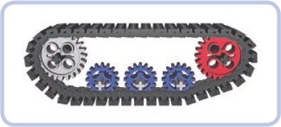
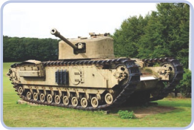
Figure 16-15. With 11 road wheels per track, the British churchill tank is an extreme example of using a design that includes many small road wheels.
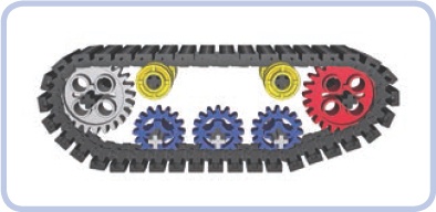
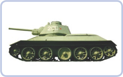
Figure 16-17. Soviet tanks from the World War II era—such as this T34—used road wheels so big that they had contact with both the lower and upper portion of the track, thus eliminating the need for return rollers.
A good example of a modern wheel system is the one used on the classic Sherman tank. It includes two large sprocket wheels, six smaller road wheels, and two return rollers per track (see Figure 16-18). Note that the forward sprocket is driven and the rear one is idle.
Now that you know what types of wheels are used in tracked vehicles, we can move on to the suspension systems.
The primary function of a suspension system is to increase stability and reduce the shock transferred to the vehicle. Its secondary function is to prevent the tracks from falling off. A suspension system achieves this function by keeping road wheels in close contact with the tracks regardless of the shape of the ground. The vast majority of tracked vehicles have suspension only on the road wheels, largely for simplicity’s sake. All the suspension systems described below are designed for road wheels but can be used with sprocket wheels as well.
Note
The type of LEGO track you use doesn’t affect the suspension; it only determines the type of sprocket wheels you can use. The examples of suspensions in this chapter show variants for both LEGO track types to demonstrate how a given suspension works with various wheels.
A bogie is the simplest type of tracked suspension. It is simply a beam that has one road wheel on either end; this beam freely rotates around a central axle connected to the vehicle, as shown in Figure 16-19. As the road wheels on the bogie go up and down, only half of their travel is transferred to the bogie’s central axle—for example, when a wheel moves upward by 2 studs, the axle will only move upward by 1, as shown in Figure 16-20. So bogies provide reasonably good flotation, but they don’t reduce shock.
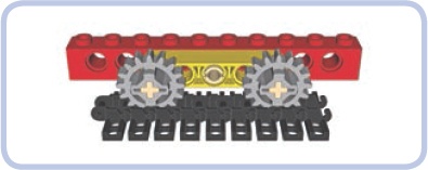
Figure 16-19. The yellow beam rotates around the central pin, creating a bogie with two road wheels.
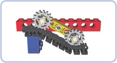
Figure 16-20. In this example, one road wheel is raised by 2 studs, but the bogie’s central axle (and thus the vehicle) is raised only by 1 stud.
Note
The basic principle of bogies is that only 50 percent of the road wheels’ vertical travel is transferred to the vehicle. But note that this principle is true only if the obstacle is shorter than the length of the entire bogie—that is, shorter than the span of two road wheels.
Figure 16-21 shows an example of a bogie for the newer LEGO track type. The newer tracks are larger and usually used with larger and heavier vehicles, which is why this bogie variant is reinforced on the front and back sides (and is therefore sturdier).
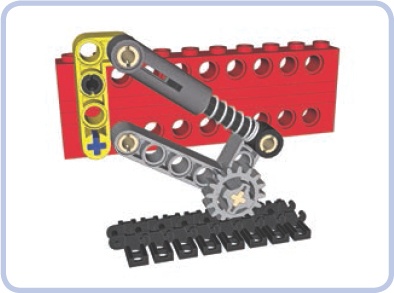
Trailing arms are used in more advanced suspension systems, where each road wheel is located on the end of an arm and supported against the weight of the vehicle by a shock absorber (or another elastic element), as shown in Figure 16-22. As most tracked vehicles usually have relatively low profiles, 6.5L shock absorbers are better suited to most tracked vehicles than their longer variants.
Trailing arm suspensions are sensitive to the direction of the tracks’ rotation, and tracks always rotate more freely in one direction than the reverse. The arms are located in front of the road wheel.
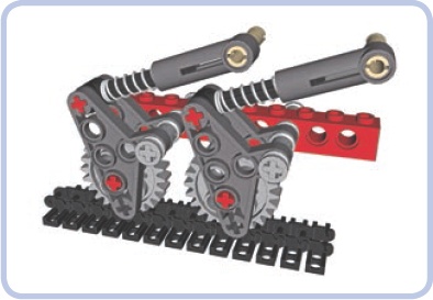
There are a number of possible variants for this suspension system, depending on how much load each road wheel has to handle, how much space you can use, and what suspension travel and hardness you want to achieve. Figure 16-22 through Figure 16-24 show some common variations.
Note
The first and last road wheels in a track usually handle more load than the middle ones. It is therefore a good idea to use harder shock absorbers for these wheels than for the middle wheels. The weight distribution of the vehicle (front-heavy, center-heavy, or rear-heavy) should also be considered.
The setup in Figure 16-23 works only with 24-tooth gears and isn’t that soft but takes little vertical space, which is helpful when you need the road wheels to be very close to each other.
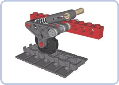
Figure 16-24 shows another compact setup that works with all types of wheels, including those for the newer track system. It allows a lower overall profile, but it needs the road wheels to be spaced farther apart.
Shock absorbers are efficient but large; their length can force us to build our vehicles taller than we would otherwise need to. Thankfully, there’s a very attractive alternative when building a trailing arm suspension: torsion bars.
A torsion bar is a long, slightly elastic element, positioned perpendicular to a vehicle’s hull. One end of the bar is locked to the chassis so that it can’t rotate. The other end is attached to a trailing arm with a road wheel on the other end, and it rotates together with the arm. So as the road wheel goes up, the arm twists the bar around its axis, as shown in Figure 16-25. And the great news is that all LEGO axles (except for the very short ones) are elastic enough to function as torsion bars.
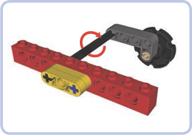
In the figure, the black 8L axle is functioning as a torsion bar; its one end is locked into the chassis (represented by the red brick), and its other end is locked into the trailing arm (represented by the dark grey beam). Now, if the road wheel at the end of the arm meets an obstacle that makes it go up, the trailing arm will oscillate around the axle, making it twist a little. Once the obstacle is passed, the axle will untwist, returning the arm and the wheel to the initial position. Of course, in a real vehicle the torsion bar needs to be supported.
Figure 16-26 shows a more complex example of the torsion-bar suspension in action, including such a support. Note that the 8L axles go through two bricks, but they are locked only with the one closer to the middle of the hull. They can freely rotate inside the outer brick, which is used only to support them.
The torsion-bar suspension requires only common pieces, and its hardness can be adjusted by using shorter or longer axles or by simply changing the point at which the axles are locked to the chassis (the closer to the trailing arm, the harder the suspension). Twisting LEGO axles may seem risky, but they are surprisingly resistant to damage. I have used 8L axles as torsion bars in a model with a total weight of around 3.5 kg, where each torsion bar handled an average load of almost 0.25 kg and a much greater load when negotiating obstacles. Even after the model went through a lot of tests on rough terrain, the axles were in pristine condition.
This kind of suspension, unlike shock absorbers, also has the advantage of using minimal space inside the tracks. Its disadvantages are that it takes 1 stud of vertical space at the bottom of the hull (as shown in Figure 16-27) and that this space is so densely filled with axles that it’s usually impossible to use it for anything else. A torsion-bar suspension also doesn’t work well for lightweight models. If the average load per road wheel is less than 100 grams, the effect of this suspension is barely noticeable.
In the example in Figure 16-27, only 1 stud of vertical space inside the hull is taken by the suspension system, but it is taken quite completely. Note that the bars on each side are separate axles—in this case, 7 studs long each. It is possible to use a single axle that traverses the whole hull as long as it’s locked securely in the middle so that twisting one of its ends doesn’t affect the other end.
Early tracked vehicles were built with road wheels of solid metal. Later, engineers observed that vibrations between the tracks and the vehicles could be reduced by putting rubber rims over the road wheels. Today, rubber rims are considered standard for real-life tracked vehicles. Note that these rims are different from conventional tires: They are made of solid rubber, they’re thin, and they have no tread.
There is an easy way to re-create a road wheel with a rubber rim using LEGO pieces so that it looks accurate: You can use a wedge belt wheel with a special solid tire (#70162), as shown in Figure 16-28.
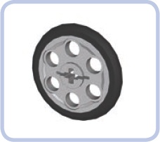
Figure 16-28. A belt wheel with a tire. The tire is solid rubber and very easy to put on and take off.
We can use a pair of wedge belt wheels to create a single road wheel that braces the track from two sides, as shown in Figure 16-29. Wedge belt wheels look more accurate while modeling some tracked vehicles, and they also allow you to build compact suspensions, as shown in Figure 16-30. (LEGO models aren’t heavy enough to effectively compress solid rubber, so the shock absorption effect achieved with these tires alone is minuscule.)
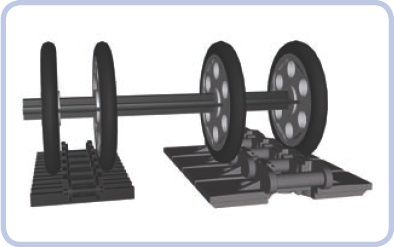
Figure 16-29. A pair of wedge belt wheels 1 stud apart can firmly secure the older type of track. If they are 2 studs apart, they can do the same with the newer type of track.
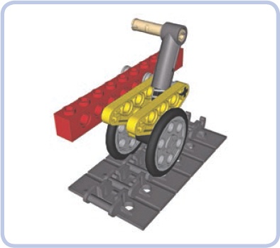
Figure 16-30. This suspension, which uses a trailing arm and a shock absorber, takes advantage of double road wheels to position the absorber as low as possible. With a central road wheel, the shock absorber would have to be moved to the outer side or be located much higher.
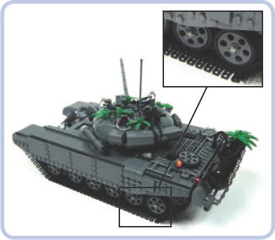
My model of a Soviet T-72M tank, shown in Figure 16-31, employed yet another approach: The wedge belt wheels with tires were simply inserted into the central portion of the track, and they held it in place surprisingly well. At the same time, they were all suspended on torsion bars.
Another interesting thing about wedge belt wheels is that without the tire, they have a diameter that perfectly matches that of certain sprocket wheels. They can be used to conceal colorful sprocket wheels for aesthetic effect, as shown in Figure 16-32 through Figure 16-34.
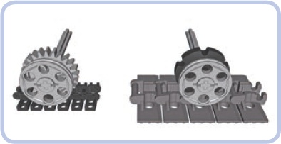
Figure 16-32. The diameter of a wedge belt wheel matches the diameter of a 24-tooth gear meshed with the central protrusion of the older track (left) or the diameter of a smaller sprocket wheel meshed with the central protrusion of the newer track (right). Thus, the wedge belt wheels can be used to conceal the real road wheels and improve aesthetics.
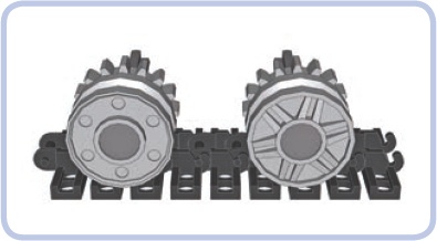
Figure 16-33. Concealing 16-tooth gears behind 18×8 mm wheels (#56902). As shown here, the two sides of these wheels look different and can be used together to create an interesting aesthetic effect.
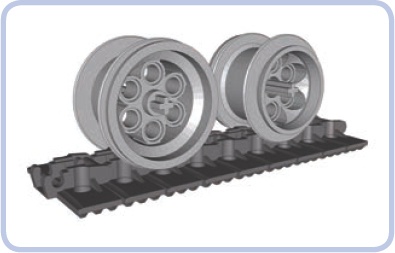
Figure 16-34. The newer type of track works fairly well with 49.6×28 VR wheels (#6595). These wheels also have two sides that look different, and their size and appearance make them very suitable for large models.
If you’re curious about how we can power tracked vehicles like tanks and bulldozers, skip to subtractors in adding more than two motors, where you’ll learn the methods of steering tracked vehicles and independently driving each track.