Builders are usually inspired to create their own models for two reasons: the desire to model a real-life object (like a favorite car or truck) or the desire to model a real-life mechanism or function (for example, a 4×4 drive or a pneumatic system). If you’re inspired by mechanisms, just look for models that could include one. When you decide to build a model, you’ll want to start by asking yourself three questions:
Can I make it work well?
Can I make it look good?
Can I find sufficient reference material to accurately model this object?
Finding a balance between the aesthetics and functionality of the model is an extremely sensitive task, and it often helps to decide which is more important to you before you start building. As you build and rebuild your models, you’ll likely reexamine your priorities. It’s best to accept one of two options before you even start building: I can compromise the look in favor of functionality, or I can compromise functionality in favor of the look.
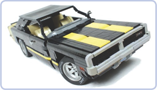
Figure 19-1. My 1969 Dodge Charger model appears to have a massive hood with plenty of space beneath it. However since I decided to model the car’s huge engine, almost none of this space was available for mechanical components, and I was barely able to fit a mechanism to lift the distinctive grille that reveals the car’s headlamps. Most of the electric components ended up in the trunk.
Looking at the silhouette of the object you want to model may also help in the early stages. Bear in mind that most LEGO pieces fit well within straight lines, right angles, and rectangular shapes. This makes trucks much easier to build than motorbikes, for example. You can, of course, use flexible axles and Technic panels to model curved, flowing shapes, but the resulting aesthetic is generally poorly received outside the Technic community and sometimes within it, as well.
Your typical car is challenging to model because of the limited space it provides for electric and mechanical components (see Figure 19-1). Big elements, such as power supplies, IR receivers, and motors, are difficult to incorporate into a car. In most cases, the only spaces available for those elements are the cabin floor, the central space between the seats, the trunk, and the space normally taken by the engine (if you choose not to include a replica of the engine in your MOC). You can also build a motor-free model, with all the functions activated manually, in the spirit of many LEGO sets.
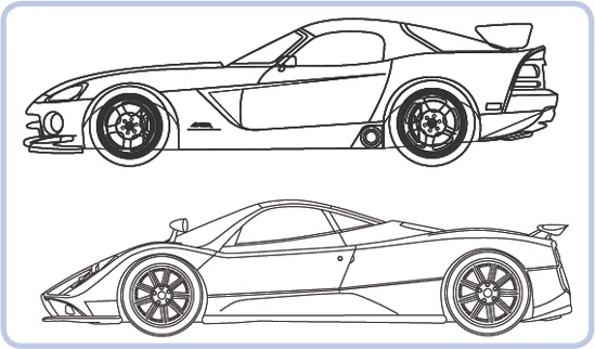
Space constraints become even more challenging with sports cars, which are slung low to the ground and often have open tops, exposing any mechanism installed in the cabin. Cars of this type often use wide tires and independent suspensions, which can result in width issues if you decide to include both in your model. Finally, as sports cars’ engines are particularly huge, choosing between a front-engine and central-engine car greatly affects the amount of space available in the front and in the rear, as well as the silhouette of the model. Figure 19-2 shows an extreme example of this, comparing a front-engine Dodge Viper and a rear-engine Pagani Zonda. Note how the silhouettes of the cars differ—the Viper’s cabin is moved far back, adjacent to the rear wheels, while the Zonda’s cabin starts just behind the front wheels. Both cars, although similar in many respects, offer different challenges and opportunities to a model builder.
Off-road cars, such as SUVs, have taller silhouettes and offer more space, especially in the chassis, but they also have more complex and space-consuming drivetrains and suspension systems. Their engines are usually under the hood, as in the Jeep Wrangler Rubicon shown in Figure 19-3. And many SUVs have hard-top bodies, making it possible to use some of the cabin’s internal space (but also making the car more top-heavy).
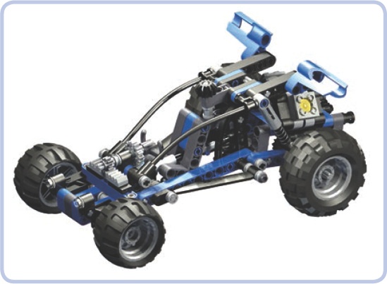
Finally, there are cars such as buggies and truggies, whose bodies are built primarily with pipes and whose internal elements are exposed, as shown in Figure 19-4. There are many ways to install elements of the Power Functions system, such as motors and battery boxes, in these cars so as to mimic the original cars’ fuel tanks and other parts.
Trucks have many qualities that make them easy to model, and they are one of the favorite themes of model builders. They are technically simple to build, and they offer plenty of space for internal components and many possibilities for experimenting with aesthetics. They are also often large enough to conceal even very complex mechanisms—for example, my tow truck model housed 17 motors.
Trucks can be divided into two categories with different appearances and different amounts of space available: longnose (or US) trucks and cab-over-engine (or European) trucks. Longnose trucks, which are designed to travel over longer distances, have a hood (or bonnet) with the engine in front of the cabin. They often have a sleeper module behind the cabin—that is, a simple structure adjacent to the cabin, where the driver can sleep or relax (see Figure 19-5). The cab-over-engine variant is generally smaller and more compact with, naturally, a simple cabin over the engine. European-style trucks have no hoods, and the optional resting space for the driver is located inside the rear part of the cabin rather than in a separate body module.
Note that trucks of both categories usually have air deflectors on top of the cabin. In longnose trucks, however, the sleeper modules may have their own extensive air deflectors that direct the air flow between the cabin and the trailer. With cab-over-engine trucks, the deflectors appear only on the cabin and may be quite tall to compensate for the difference in height between the cabin and the trailer, as shown in Figure 19-6.
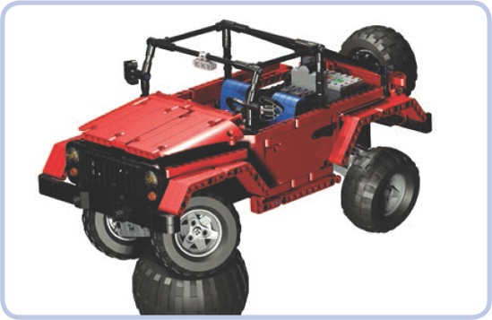
Figure 19-3. My model of the Jeep Wrangler Rubicon, which is a small open-top car, had motors under the hood and the battery and IR receiver in the trunk. This way it had a good weight distribution and plenty of space left for some decorative elements in the cabin interior, including seats and the steering wheel.
Longnose trucks definitely have more advantages for model builders: They offer more internal space, especially with the addition of a sleeper module, and there are more ways to experiment with their aesthetics. Note that in the trucks with no hood—longnose and cab-over-engine alike—the engine is accessed by lifting up the cabin, which tilts forward. This is difficult to include in a model, and engines are often omitted completely from the models of cab-over-engine trucks, especially since engines use space that is best suited for the steering system. Trucks with hoods, on the other hand, can have working hoods with replicas of the engine beneath, and this still leaves plenty of space below the cabin for steering mechanisms. As Figure 19-7 shows, the space under the hood can be used to create a fairly complex engine replica, as well as to house some electric components.
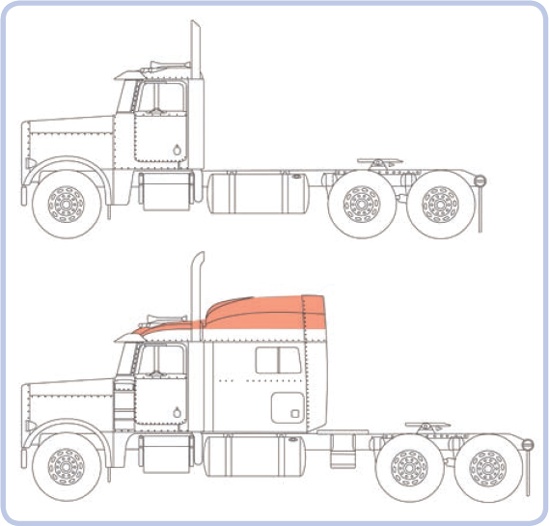
Figure 19-5. The longnose Peterbilt truck, shown without the sleeper module (top) and with sleeper module (bottom). The air deflector is marked with orange.
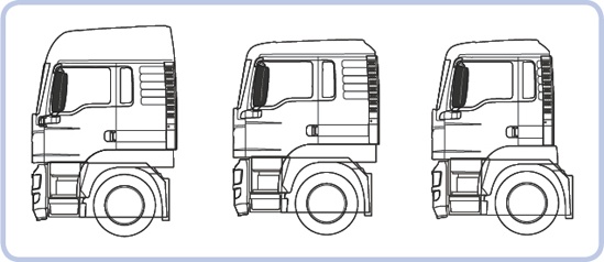
Figure 19-6. Three cabin variants of the same European MAN TGS truck (from left to right): with tall airfoil and resting space, with low airfoil and resting space, with low airfoil and no resting space
Motorcycles, like the one shown in Figure 19-8, are very challenging to model for a number of reasons—the most important one being the fact that they have only two wheels. In order to stand on its own, a model requires at least three wheels (or wide, flat tires). To enable a motorcycle model to stand on its own, we can add a small, unobtrusive wheel or a full sidecar. Sidecars have the advantage of offering plenty of internal space near the bike’s rear wheel, so they can be used to house a propulsion motor. Another alternative is to build a trike or a quad, which is something like a four-wheeled bike.
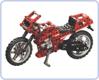
Other difficulties you may encounter while building bikes include motorizing the steering system, the limited variety and size of matching LEGO wheels, and the overall small size and exposed body, which make it difficult to install any large electric components. All in all, motorcycles are aesthetically interesting models to build but difficult ones to motorize. Among the LEGO sets, as well as among MOCs, most motorcycles have only basic functions, such as a suspension system and drivetrain with a replica of an engine, while motorized models are a rarity. For an example of a motorized model, see Figure 19-9.
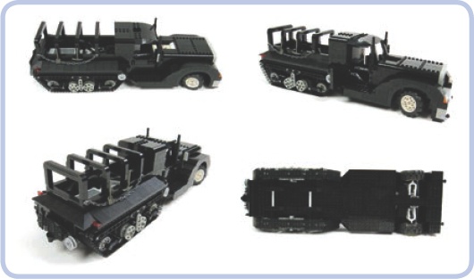
Tracked vehicles are a diverse group, but they are almost always fairly easy to model. First of all, the use of the tracks eliminates the need for any complex steering system (unless we decide to use a subtractor). Secondly, the suspension system is located either on the sides or on the bottom of the hull, taking little or no space inside the model, as shown in Figure 19-10. In fact, the hull of most tracked vehicles is a simple box with tracks on its sides and plenty of space inside, and it also functions as a body frame.
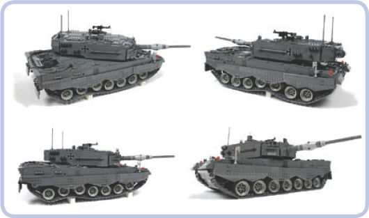
Tanks have large hulls whose space can be arranged in several ways. After building plenty of tank models, I have developed a reliable arrangement: The propulsion motors go in the lower-rear part of the hull, with IR receivers on top of them. For modern tanks with large turrets, the receivers have to be moved to the very rear end of the hull to avoid being blotted out. The central part of the hull can house the power supply with the turret rotation mechanism on top of it. The front part can be used for the power supply as well, but not for the IR receivers, as the models are typically controlled from behind. The turret itself can house the gun control mechanism, but it’s also a good, well-exposed place for the IR receivers if it’s tall enough to house them. See examples of tanks I have modeled in Figure 19-11 and Figure 19-12.
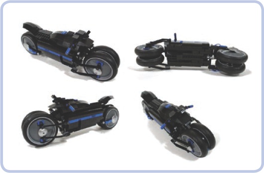
Figure 19-9. The Dodge Tomahawk concept motorcycle comes with double front and rear wheels, thus providing four fulcrums rather than two. I built a motorized model of this bike to prove that it could be motorized and drive stably; however, it couldn’t turn because it was too small to house a steering system and a propulsion system at the same time.
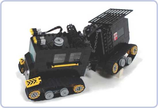
Figure 19-10. The Swedish Hagglunds BV 206 personnel carrier consisted of two parts connected by an articulated joint. This very tiny model housed one steering and two propulsion motors, a battery and an IR receiver, while its simple suspension was located entirely within the tracks.
You might also want to model half-track vehicles, which have regular steered front wheels and tracks replacing the rear wheels, as shown in Figure 19-13. This rare combination is used almost exclusively in military vehicles, such as trucks and armored personnel carriers. Most of the vehicle, including the cabin, the front axle, and the engine bay, needs no alteration from a wheeled version, while the tracks need no steering system, as steering is provided by the front wheels. Some of the heaviest historical half-tracks, however, included a braking system that slowed one of the tracks while turning to improve handling of the vehicle.
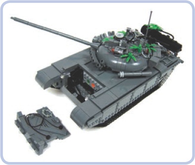
Figure 19-11. My T-72M tank model was small and low, with an angled glacis plate that left very little space in the front of the hull. The very front of the hull housed only some wires, and the glacis plate was removed to access the battery.
Modeling aircraft offers plenty of intriguing possibilities and challenges. Such vehicles can be motorized to have rotating propellers or turbines. They can also have working ailerons, elevators, and rudders, as well as retractable gears and flashing position lights. But LEGO aircraft can’t fly.
Note
Building a 100 percent LEGO plane or helicopter capable of flying is physically impossible because of the weight of LEGO pieces and the limited power of LEGO motors. Additionally, an aircraft built exclusively with LEGO pieces would have difficulties with balance and with achieving an aerodynamic profile.
Any aircraft you model can be made even more impressive when installed on a boom that can lift it up and move it around, imitating free flight. The LEGO 8485 set includes such a model, shown in Figure 19-14.
One of the main challenges involved in building a model of a plane is the shape of its hull. A plane hull’s cross section is more or less circular. You can model it with studfull pieces using curved slopes, or you can just mark some edges of the hull with flexible axles. The wings and tail can be modeled with slopes, plates, and tiles, or with axles or even bricks and beams if you mark only the edges, as Figure 19-15 shows. Minifigure-scale planes can use the ready-made tails, noses, and hull sections that can be found in regular LEGO sets.
Your model can also take advantage of one of the large number of ready-made LEGO propellers, shown in Figure 19-16. These propellers can work in air as well as in water, and when motorized, some of them can generate thrust that is noticeable, though still insufficient for flying.
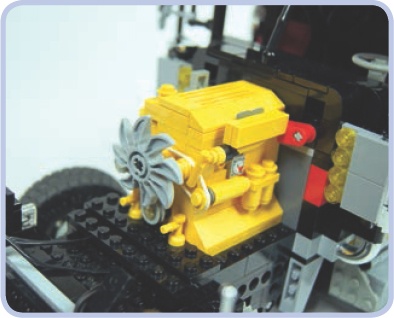
With jet engines, it’s relatively easy to create mock-ups of turbines that can rotate. Figure 19-17 shows a simple example of a mock-up built around a 4-stud-long bar. You can also use LEGO LEDs with translucent red or translucent orange pieces to illuminate the engine’s nozzle. Installing a small LEGO propeller inside a duct with a round cross section can generate more thrust than when the same propeller works outside the duct.
Helicopters are generally easier to model than planes. They have dense hulls, tiny wings or no wings at all, and a single boom with a tail rotor. They offer plenty of internal space and often include more functions than planes do: Some helicopters come with winches to lift loads off the ground, some come with retractable gear, and even the simplest helicopters have large rotating blades that look impressive when motorized.
When it comes to modeling a helicopter, the primary challenges are the windscreen, which has a complex shape in some machines, and the rotors. A typical helicopter comes with a single main rotor with two to six blades and a single tail rotor with two to four blades. Figure 19-18 provides an example of a helicopter with a six-bladed main rotor, which helps the aircraft handle its weight. Some helicopters, such as the Kamov Ka-50 Hokum, come with two main rotors and no tail rotor. The two rotors rotate in opposite directions, and if they are coaxial—which is not always the case, as Figure 19-19 shows—modeling them can be an interesting technical challenge.
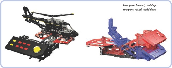
Figure 19-14. The LEGO 8485 Control Center II set features a large helicopter on a simple boom (left). By manually lowering the control panel (right), which acts as the helicopter’s counterbalance on the boom, we can lift the model up and simulate the movement of free flight—for example, the tilting of the hull.
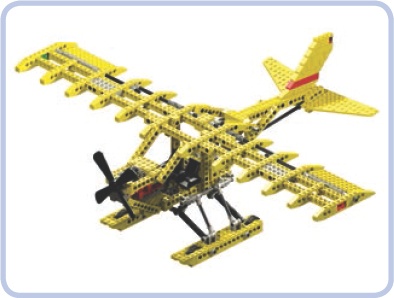
Figure 19-15. The LEGO 8855 Prop Plane set is a fairly typical example of a Technic plane. It has no motors and just basic functions, with parts such as ailerons and elevators controlled by a single yoke.
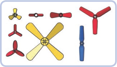
Figure 19-16. The LEGO ready-made propellers with pin holes (red) and axle holes (yellow), along with the #2952 propeller (blue), which can be used in pairs to create a 1-stud-thick, four-bladed propeller.
The tail rotor is usually located on one side of the tail fin. In some helicopters, however, it is mounted inside an opening in the fin. Such a design, shown in Figure 19-20, is called a fantail, and rotors used in it are smaller and have between 8 and 18 blades. It’s very difficult to properly model a fantail because there is no easy way to mount and drive a LEGO rotor inside it.
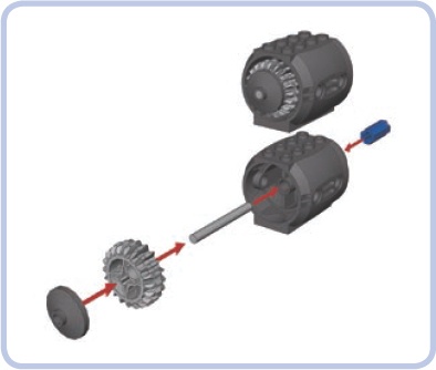
Figure 19-17. One of many ways to build a small mock-up of a turbine engine with just a few LEGO pieces. The axle joiner (blue) allows us to connect the central bar to a regular axle and thus motorize the “turbine.”
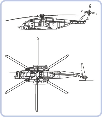
Figure 19-18. The Sikorsky MH-53 Pave Low is a massive military transport helicopter. Its six-bladed main rotor helps to handle its weight, which can reach 21 tons when the chopper fully loaded.
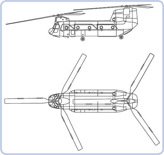
Figure 19-19. The Boeing CH-47 Chinook also comes with two main rotors, located at opposite ends of the hull and at different heights. Such an arrangement is called a tandem.
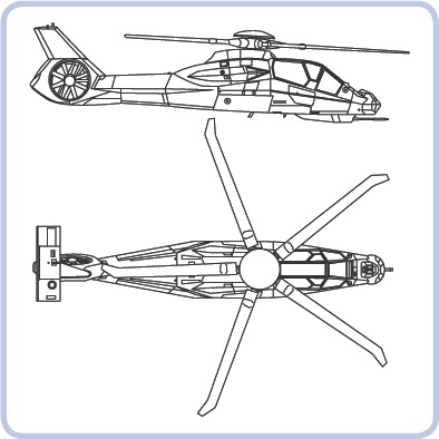
Figure 19-20. The Boeing Sikorsky RAH-66 Comanche was designed to be an advanced reconnaissance and attack helicopter. It used a fantail instead of a typical rear rotor, and the complex shape of its hull resulted from incorporating stealth technologies.
The real main rotor head of any helicopter is an advanced mechanism, allowing adjustments to the pitch of its individual blades or all blades together to weather conditions. This enables the vehicle to perform complex movements, such as flying backward or sideways. A simple mechanical solution allowing the rotor to tilt forward and backward or left and right is shown in Figure 19-21. Tilting the rotor in multiple planes is also possible with the use of towballs and links, as shown in Figure 19-22.
The rotor itself consists of a rotor hub with blades attached around it. The blades can easily be built with plates and tiles or with ready-made pieces from the 9396 Helicopter set, though building the rotor hub to connect these blades can be more difficult. Figure 19-23 to Figure 19-25 show example hubs, with short red plates noting blade placement.
Now that you’ve seen the possibilities and challenges of different vehicle types, it’s up to you to choose what to model. Assuming that you have a model in mind ready to scale, proceed to the next chapter, which explains how to model it accurately.
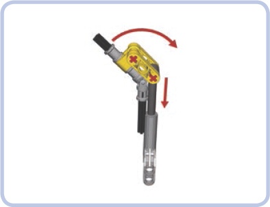
Figure 19-21. An example of a simple rotor-tilting mechanism. The black axles with a universal joint are the driveshaft, connecting the rotor on the top with a motor on the bottom. Retracting and extending the linear actuator changes the angle of the axle above the joint and thus of the whole rotor.
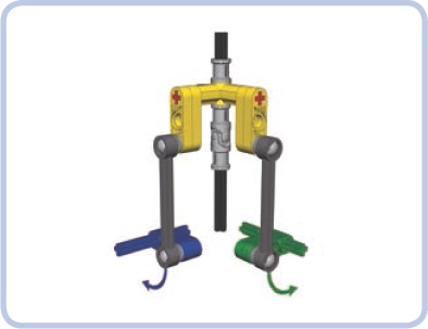
Figure 19-22. A mechanism for tilting a rotor in two planes. Rotating the green axle tilts the rotor in one plane—for example, forward and backward—while rotating the blue axle tilts the rotor in another plane—for example, left and right. Thanks to the use of links and towballs, both angles of the rotor can be changed simultaneously without interference.
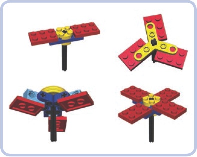
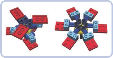
Figure 19-24. A six-bladed hub can be built by doubling the three-bladed version or by simply attaching the blades to a wedge belt wheel with pins so that the centrifugal force of the rotating rotor aligns them.
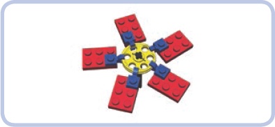
Figure 19-25. Finally, a hub with any number of blades can be built by attaching 1×1 plates with clips to the edge of a wedge belt wheel. This solution, invented by Polish builder Marcin “Mrutek” Rutkowski, results in a surprisingly robust setup, which can be made even stronger if you attach blades using two wedge belt wheels and two clips. You will, however, need to align the blades by hand, so a protractor may be useful.