
Now we are ready to commence our picture guide detailed in a step-by-step tour of a PV solar rooftop system installation. For the reader’s convenience, the entire illustrated process is divided into four general “Photo Groups” and each “Group” is divided into several “Steps.” Each “Step” is further divided into several photos, all in chronological order of the installation process.
1. In the photo, we can see the installer has located the main service panel and in this instance we can see that he is in the process of installing a combination PV meter/main service panel.
2. This photo shows the inside of the main service panel being installed and integrated with the utility meter. The installer is about to install as many internal circuit breakers as the home may require. Most will be 120V breakers but a few will be 220 to 240V breakers for certain appliances, such as the electric water heater.

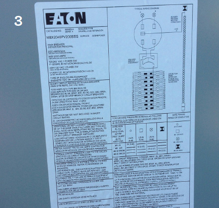
3. This photo shows the large label that contains all the specifications of the main panel. You will find this label affixed inside the main service panel door.
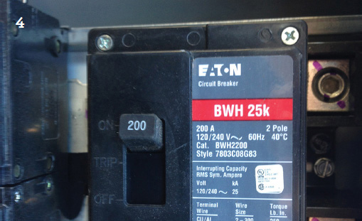
4. This photo is a close-up of the main breaker inside the main service panel. Notice that the switch is labeled with the overall amperage of the panel—in this case, 200 amps. In terms of electrical infrastructure, this is a fairly large home.
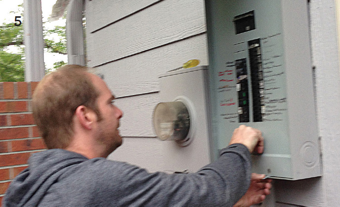
5. This photo shows the site evaluator removing the face plate of the main service panel. Since this is a new installation, he is in the process of inspecting the main panel to see that all connections are secured and tight.
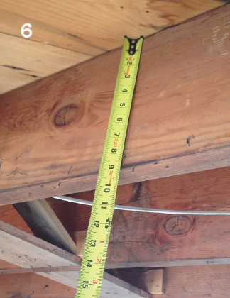
6. In the photo, the installer is measuring the sub-roof structural beams. We can see by the tape measure that the width of these beams is a standard 9 inches, which is sometimes quoted as 10 inches.
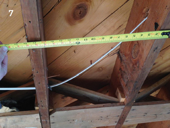
7. In this photo, the installer is measuring the spacing between structural members. In this case it is a standard 16 inches between centers. With these two measurements we can easily find the load bearing capacity of this roof per square foot. To determine the load limits for specified open areas, we also need the length of the open beams between vertical supports. Standard load bearing tables will give us the answers. The lumber supply depot supplies tables with this load bearing information.
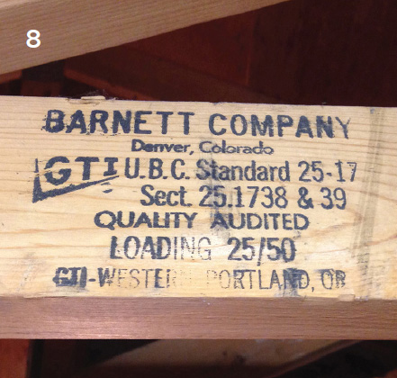
8. The information in this photo, namely the data printed on the side of the main beam, provides us with the basic truss identification and the manufacturer or the supplier/distributor can supply the load bearing tables.
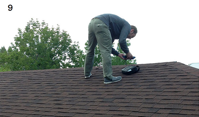
9. In the photo to the right, we can see the site evaluator is taking solmetric readings to determine the level of solar access. This is the key number for calculating the average seasonal solar production that can be expected from each PV module and from the total array.
You do not have to possess a solmetric measuring device. As explained in detail in subsection 5.6, you can obtain the insolation or irradiation index number for your precise location from the table provided, and also from the website identified in the same subsection. We explain how to use this irradiation index number, which gives you the average number of “sun hours” (summer average, winter average, and yearly average) for practically any location in North America.
10. In the photo to the right, we see the DIY installer is taking accurate measurements of the roof surface to calculate a simple plan for a potential layout for the PV array.
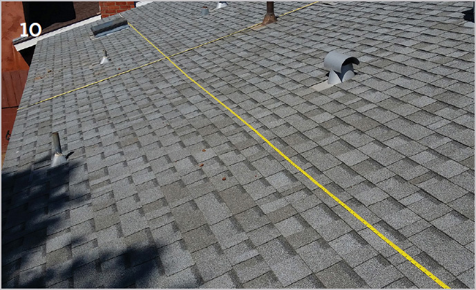
11. In the photo to the right, we see the DIY installer is taking and recording careful measurements from the edge of the roof to all the built-in roof obstructions. These measurements will enable the installer to prepare a drawing with an optimal and accurate layout for the panel array.

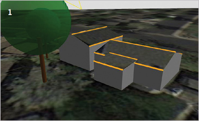
The objective here is to avoid shading onto the PV panels from nearby trees or other rooftop structures (chimneys, satellite dishes, etc.).
1. This is a frame taken from a simple 3-D modeling software that enables the homeowner to evaluate the effects from possible shading on the roof surfaces at different times of the year caused by nearby trees, other buildings, chimneys, satellite dishes, and other roof structures. This can be very useful for choosing a general layout and configuration for how you will eventually mount your solar array.
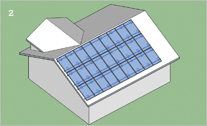
2. The image here is a 3-D rendering of the solar array as it is proposed to be mounted of the south slope of the roof. It is prepared on a user-friendly software that allows the homeowner to get a bird’s eye view of what a 27 module array would look like in different configurations on the rooftop before deciding on a final layout configuration. Spacing can easily be adjusted to allow for a chimney or other obstruction as may be required.
3. In the image on the next page, our DIY solar coach has prepared an interactive graphic that enables the homeowner to experiment with alternative layouts for the array. In this example, there are a total of 27 modules divided into two strings, or groups, one string of 13 modules at the lower section of the roof and the other string of 14 modules fits into the space immediately above the lower 13 PV panels. The model indicates the positioning of the rail supports under the array of modules. It also displays the location of the junction box (lower right) and conduit that will contain the DC wiring of the modules (“homeruns”) and channel the wiring safely from above the roof and down through the roof to the AC disconnect switch located below on the side of the house under the eaves trough.
4. In the photo, we see the DIY installer is in the process of choosing the best angle against the horizontal to enable the solar modules to optimize energy production. He does this by adjusting the height of the 3 vertical supports (that are each fixed at the bottom end of each support) to a fixed steel flashing bolted into one of the roof joists with lag bolts (see close-up photos below) and the flashing is fitted topside, above the shingles, with a mounting bracket that attaches to the vertical support. The same vertical support at the top end is attached to a long horizontal support tube and this tube is attached to the upper section of the 4 PV panels. Your solar contractor or installer will supply all of the specified items of the support hardware required by your PV panel supplier, if you are using one.
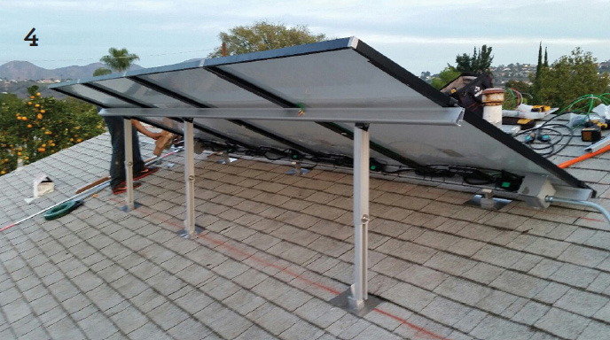
The small array above of 4 modules may be additional to modules installed on the other side of the roof to increase total system production, or, on the other hand, the main array might be mounted on this side to avoid a shading problem on the other side.
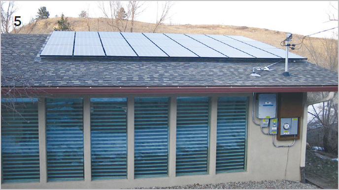
5. In this photo, the installer has mounted the PV panels in an array on a plane parallel to (or flush with) the surface of the roof. Even if the flush mount does not give the optimum tilt angle, it is often used for ease of installation and aesthetic reasons. Lowering the tilt angle below the optimum angle will result in very minor energy losses. (See details in Chapter 5.) In the lower right-hand corner of the photo we can see the location where the homeowner decided to install the central inverter, disconnect switches, main distribution panel, metering device, etc. This is apparently at the back of the house beside the living room windows. If you look closely you will also see the sky is partially overcast with sunshine at the top of the hill behind the house but with shade on the PV panels. So at this particular moment, we can assume that the PV solar rooftop system is not generating any power.
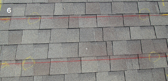
6. In this photo, the DIY installer has just laid out the parallel markings (red lines) for the panel support mountings. The yellow 90-degree markings indicate the corners of a two-module group. The yellow circles indicate the drill points where the lag screws will attach the steel flashing mounts to the roof joists just below the shingles. The exact location of the joists is revealed to the installer with the use of a quality electronic handheld stud-finder with the depth reading adjustment button set at maximum depth. This instrument is not expensive and it is accurate and reliable. The DIY installer will definitely want to buy one if he doesn’t already own one.
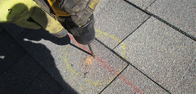
7. In the photo, the installer is drilling a pilot hole for the flashing. The procedure to determine the exact locations for the drill holes and lag bolts is explained in detail in the subsection of the previous photo. For this job, if you are a DIY installer, you will need a good quality 1/2 HP portable electric drill with a spare rechargeable battery and a good set of drill bits if you don’t already own these items.
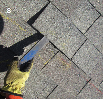
8. In the photo, the installer is prying up a shingle where the steel flashing will be inserted between shingles and secured with a lag bolt to a roof joist below the shingles to hold the mounting framework.
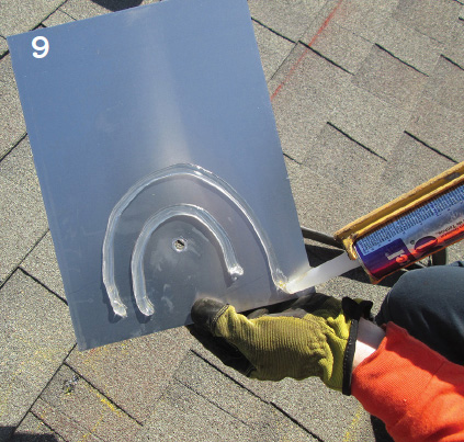
9. In the photo, we see the installer applying a clear silicon sealant in a double semicircle fashion to the back of the steel flashing. The sealant semicircles will be pointed downward when the flashing is in final position and this way water leakage through the roof at the point of the lag bolt is prevented.
10. In the photo, the installer is applying the sealant to the pilot hole. This is a backup precaution in addition to the sealant applied to the underside of the steel flashing to prevent rainwater from getting into the hole. The hole in the center of the flashing will then be lined up with the pilot hole as shown in the following photo.

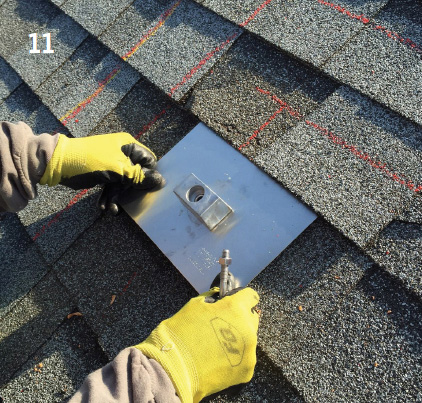
11. In the photo, we can see the DIY installer is fitting the steel flashing with a mounting bracket between the shingles as indicated by the red markings.
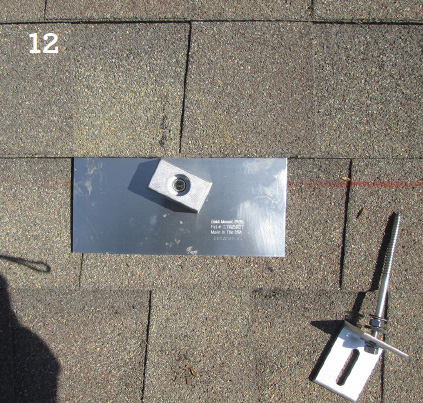
12. In the photo, we can see the installer has inserted the steel flashing into position between the shingles.
13. In the photo, we see the installer has positioned the lag screw ready to be screwed into the roof support framework joists immediately below the shingles. Drill holes are positioned with the use of a good quality “stud finder.” The details of this procedure are discussed in the subsection of the photo above.
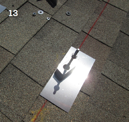
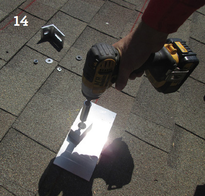
14. In the photo, our DIY installer is in the process of installing a lag screw into the roof support beam below the shingle. The lag screw will provide strength to the support framework rails that will be attached to one or several solar modules. (See additional photos below.)
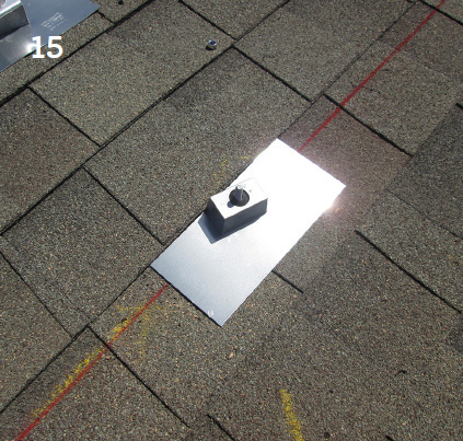
15. In the photo, we can see one of the flashings that has just been installed.
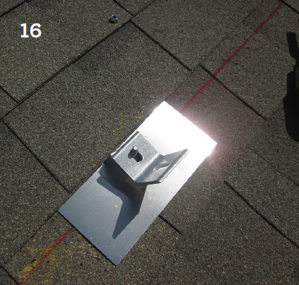
16. In the photo, the installer has just prepared the steel support bracket for drilling through the flashing to the roof joist below. The joists below the shingles can be precisely located with a good quality large depth stud-finder.
17. In this photo, we can see the DIY installer is midway through installing one of the steel support brackets. Vertical supports will then be attached to a horizontal support railing. In this way, all the vertical supports will connect the horizontal railing to all the support brackets as illustrated in the photos below.
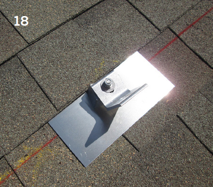
18. In the photo, we see the installer has just finished installing the steel support bracket on top of the steel flashing in line with the same red marking that lines up with the support brackets on either side of this one. This is how the vertical supports will align properly with the horizontal railings. Each PV solar module is attached with fittings called end-clamps or mid-clamps (see close-up photos below) to 2 horizontal railings, one about 20 centimeters from the top of the module and the other also at 20 centimeters from the bottom of the module. This means that each module or panel is attached firmly at 4 points around the outside of the panel to hold the panel tightly and securely, even in high wind conditions.
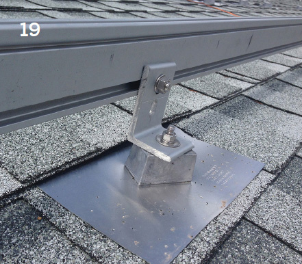
19. In this photo, our DIY installer has just attached the support hardware (90 degree steel bracket) to the roof on top of the steel flashing with a steel spacer and he bolted the bracket onto the lower horizontal railing of the mounting frame support. The 2 horizontal railings (upper and lower) will provide the mounting support framework for the solar panels.
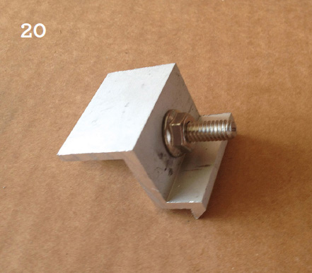
20. End-Clamp
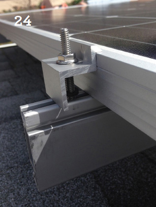
A close-up photo of an “end-clamp.” Two end-clamps attach the outside edge of one of the PV modules to the support railing. Usually there are 2 or sometimes 3 rows of modules in an array, so this means there would normally be 4 or 6 end-clamps on the same railing on the left and the same number of end-clamps on the right where the array ends.
21. Mid-Clamp
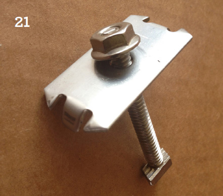
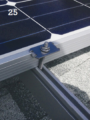
The other fitting shows a close-up photo of a “mid-clamp.” There are usually 2 mid-clamps on the left and right of every module except for modules that are on the outside of the array, since the outside edge will be secured to the support railings logically with end-clamps, not mid-clamps.
We recommend that the DIYer purchase a few extra end-clamps and mid-clamps because a worker might accidentally kick one or two clamps lying on the roof into the garden and they won’t be easily found. A little precaution here may save a lot of time not having to stop work to go to the suppliers shop to buy more clamps.
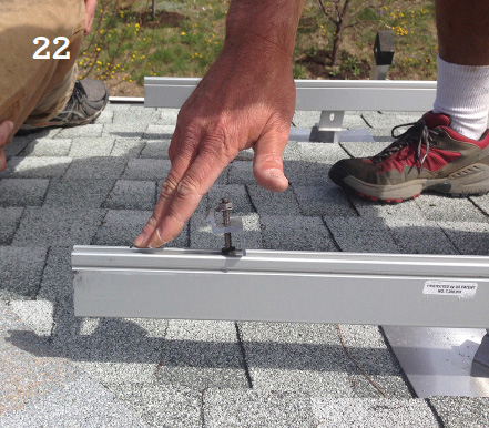
22. In the photo, the installer and his assistant are installing 2 end-clamps on the horizontal support railings, getting ready to secure an outside PV module.
23. In the photo on the next page, our DIY installer is using an open-end wrench to tighten up one of the 2 end-clamps (upper and lower), which will attach the PV panel outer frame to the horizontal support railing.
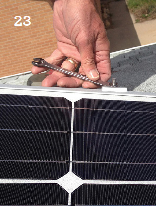
Also, in the photo, we can see that this PV installation is using monocrystalline silicon PV modules as opposed to polycrystalline silicon modules. The differences in appearance and performance and the various pros and cons of these two types of modules are discussed and illustrated in Chapter 1.
24. In the photo on the next page, the DIY installer has captured a good close-up shot of exactly how an end-clamp is attached to the support railing below and how the clamp secures the solar panel above to the support railing.
25. In the photo, we can see that the DIYer has installed one of 2 mid-clamps, getting ready to install the next panel parallel to the panel already installed.
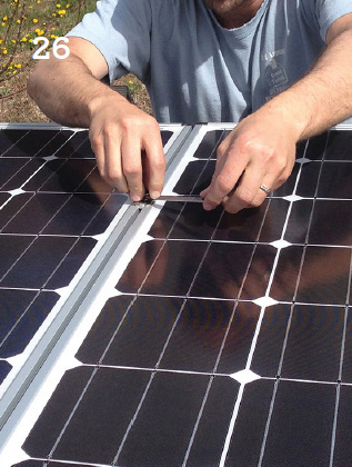
26. In the photo, the installer is using a standard open-end wrench to tighten 2 mid-clamps holding in place 2 modules in perfect parallel position to one another.
27. In the photo, the installer has just connected the wires (homeruns) from the PV panels together and he is feeding them down through the shingles of the roof through a waterproof steel and rubber fixture called a “weather-head.”

The homeruns are then connected to a DC disconnect switch and then to the DC/AC inverter installed on the outside of the house in the electrical equipment area. More details are provided in photo groups 3 and 4.
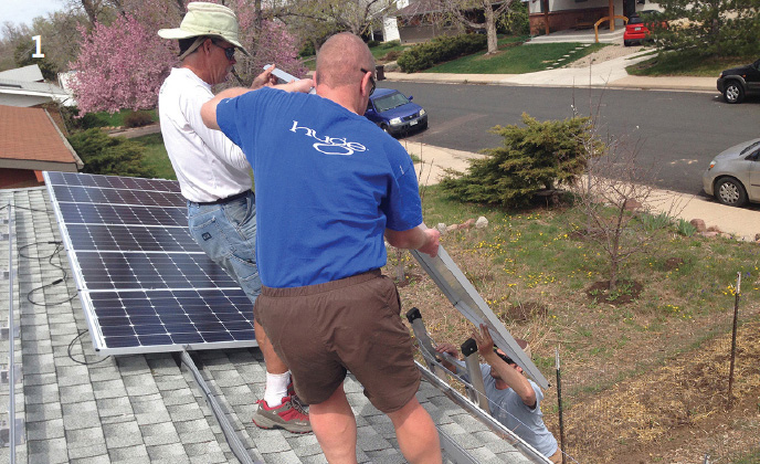
1. In the photo, the DIY homeowner and his assistant are manually uploading a solar panel from the man on the ladder (there is another helper at the bottom of the ladder). In this manner, each PV module can be safely and manually transferred from the ground level or the driveway up to the roof.
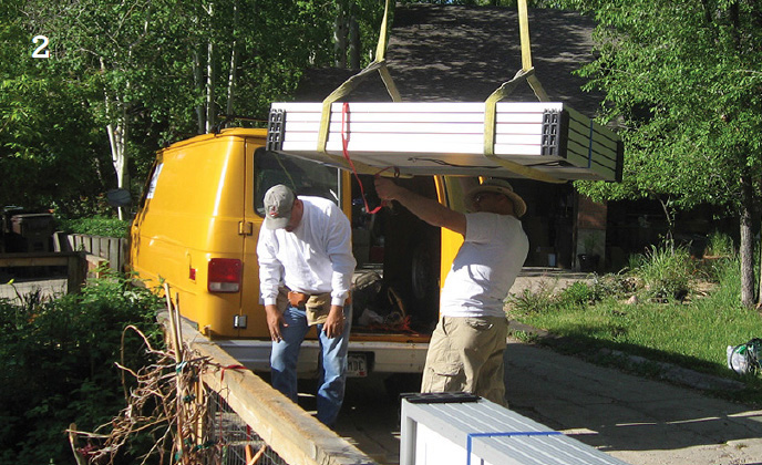
2. In the photo, the DIY installer’s assistants are helping the delivery truck and crane to unload the solar PV modules and rails at the job site. These workers should be wearing construction hard hats and for safety should avoid standing directly under the load.
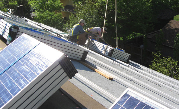
3. In the photo, we see the DIY installer and his crew guiding the crane driver and unloading the PV module packages onto the roof from the truck below. Notice that the horizontal support railings have already been installed and provide a bracing to prevent the module packages from sliding down or falling to the ground. A precautionary note: Be careful not to unload your module bundles in an unsafe position or on a dangerous slope of the roof where they might slide down and get damaged.
This is a fairly large installation but for smaller systems, the installer and his crew will often manually raise the PV modules up to the roof one by one using a ladder.
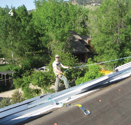
4. In the photo, we see one of the installer crew using the recommended safety harness with a safety rope firmly attached at the peak of the roof. When handling fragile, heavy loads, you must always think “safety first.” Not only for the safety of the PV glass and aluminum modules, but also for the safety of yourself (if you are a DIY installer) and for the whole installation crew.
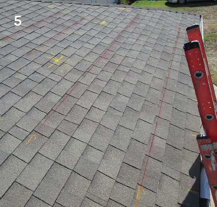
5. In the photo, we can see that the DIYer is using an insulated fiberglass ladder that provides another measure of safety. Standard aluminum ladders are not recommended since they can act as electrical conductors. Once again, think “safety first!”
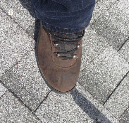
6. The photo demonstrates the kind of steel-toed standard safety boot recommended to be worn at the job site by all members of the installation crew.
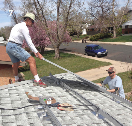
7. In the photo, the DIY installer and his assistant are in the process of installing the first PV module after they have installed the horizontal support rails. You will observe that the installer is not wearing his safety harness, a common lazy habit we recommend you avoid. “Safety first” should always be the number one rule for crews working on rooftops.
8. In the photo, we can see the DIY installation crew is in the process of installing the first PV module of the array on the bottom right hand corner of the roof. An observant reader may notice that the horizontal support railings are installed parallel with the bottom edge of the roof and that they are also secured equidistant from both the top and bottom edge of the module. When firmly installed, this mounting arrangement gives optimum strength for the modules to resist high wind conditions without damage.
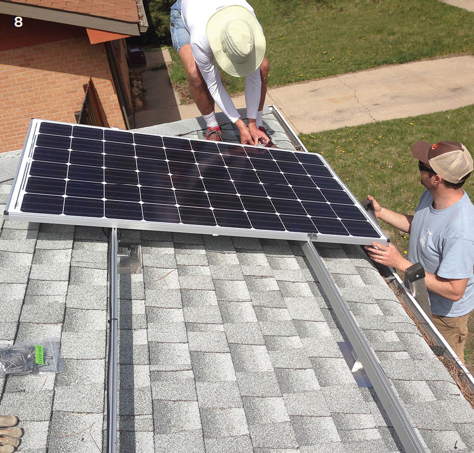
9. In the photo, the DIY installer has selected the approximate position for installing the end module at the opposite end of the bottom row of the array.
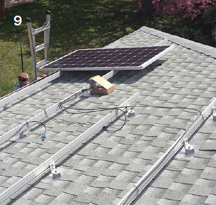
10. In the photo, we can see that the install crew is getting ready to attach a “tension string marker” for the purpose of aligning the bottom row of modules. This process is continued in the next photo.
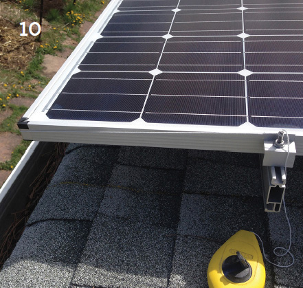
11. Here, in the photo, we can see the installer has tightened the alignment string marker the entire length of the bottom row, which will facilitate aligning all the panels in the bottom row to be parallel with the edge of the roof and parallel with each other.
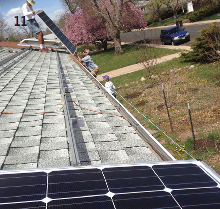
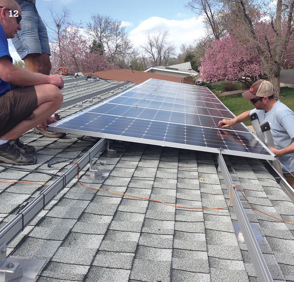
12. In the photo, we can see that the install crew has progressed and is now lining up and installing module (approximately) number 9, working from right to left. By taking extra care in the proper alignment of the bottom row of PV modules, the DIY installer is ensuring that the second and third rows will also be perfectly aligned and this will give an attractive finish to the final array that would make any homeowner proud of his PV solar system.
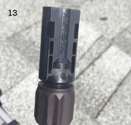
13. The photo is a close-up shot of a female connector used to interconnect the modules together. These are used with quick-connect male connectors (as shown in the following two photos).
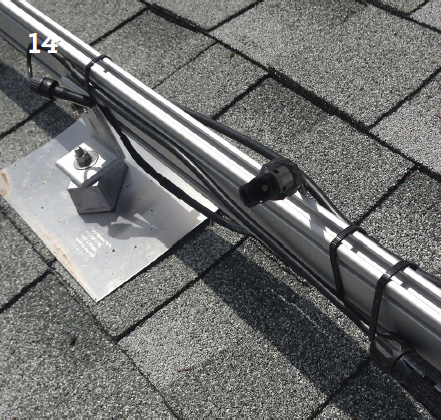
14. In the photo, we can see that the install crew has just mounted an upper railing to which they are attaching the PV DC conductor wires or homeruns between the modules. These wires are secured to the railing with plastic tensor strips to resist high winds and will not be visible after the modules are installed, but the male–female connections will remain accessible for service if needed.
15. This close-up photo shows a male and female connection that have been attached to one another and this line is labeled as part of “string 1” that includes the 13 modules of the bottom row shown in the photos above.

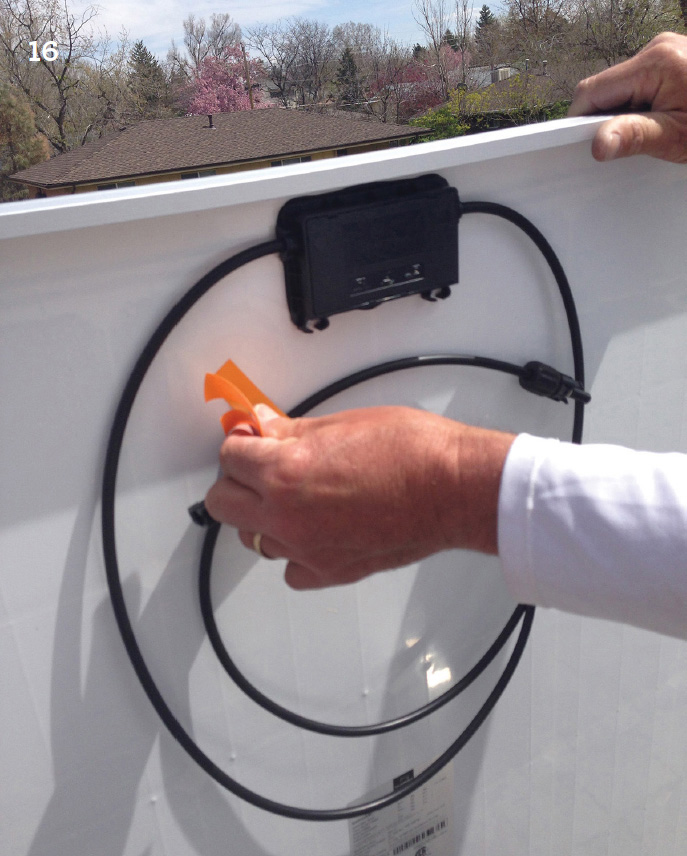
16. The photo shows how the cables or leads arrive from the manufacturer, carefully taped to the back of the panel so they’re easy to free up when the installer is ready to interconnect the modules into a “string.” It appears that our DIY installer is about to install and connect this PV panel.
17. The photo shows the DIY homeowner or his helper in the midst of wiring the first 3 PV modules of the bottom row of the array.
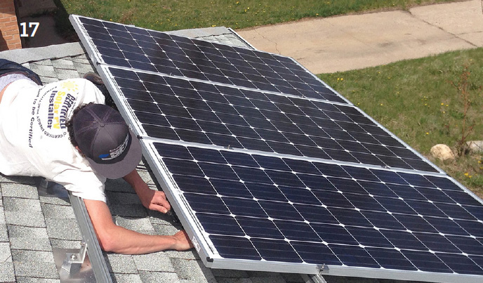
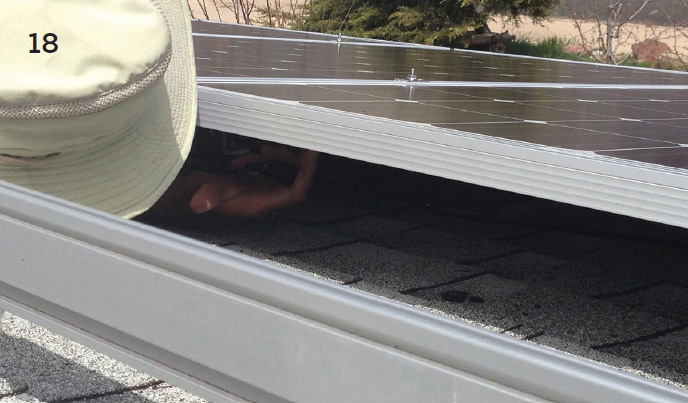
18. As shown here, it can be a bit of a tight fit to make the final connection between the leads of adjacent PV modules but the mounting support frames are engineered to allow a normal size person or worker to reach under the modules and complete the task of wiring the system.
1. This is a close-up photo showing how the installer has just attached a junction box at the end of a string of PV modules (the array). The junction box simply unites several PV production wires or homeruns from the modules and combines them to run through the Electrical Metal Tubing (EMT) commonly referred to as the conduit, which then passes through a waterproof fitting from above the roof to below the roof where the wires will be connected to the electrical controls in the equipment area.
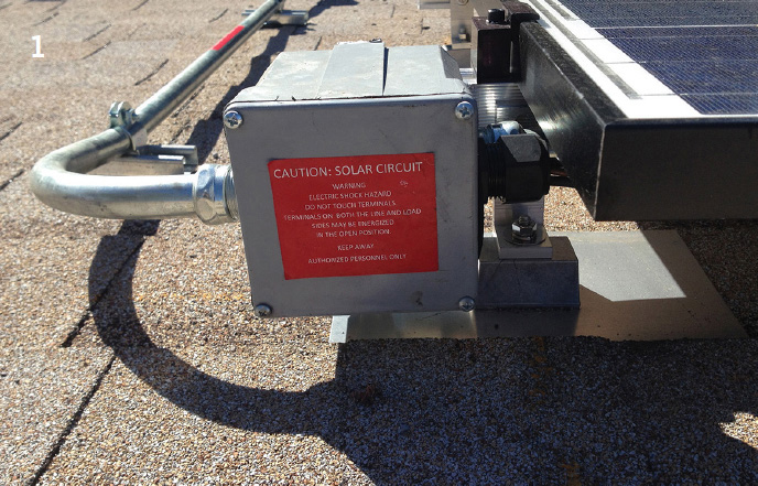
2. The photo is taken from the other side of the junction box and it shows how the DIY installer can use the conduit and a 90-degree conduit fitting to penetrate the roof. Notice the use of silicon to weatherproof the holes. The alternative is to feed the homeruns directly through a weather-head.
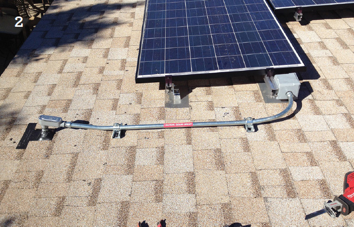
3. The photo shows how the DIY-install crew makes a 90-degree bend in the conduit tubing without the need to connect or disconnect interior wires. This part of the conduit is held in place by a steel flashing, clamp, and lag bolt.

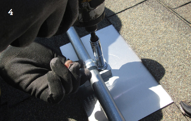
4. In the photo, we can see the DIY-install crew is attaching the conduit to a flashing with a lag bolt, spacer, and clamp.
5. The photo shows a DC disconnect switch installed after the PV panels and just before the central inverter. When activated, this switch will isolate the solar modules when the inverter needs inspection or servicing, or for adding additional modules or other modifications to the system.

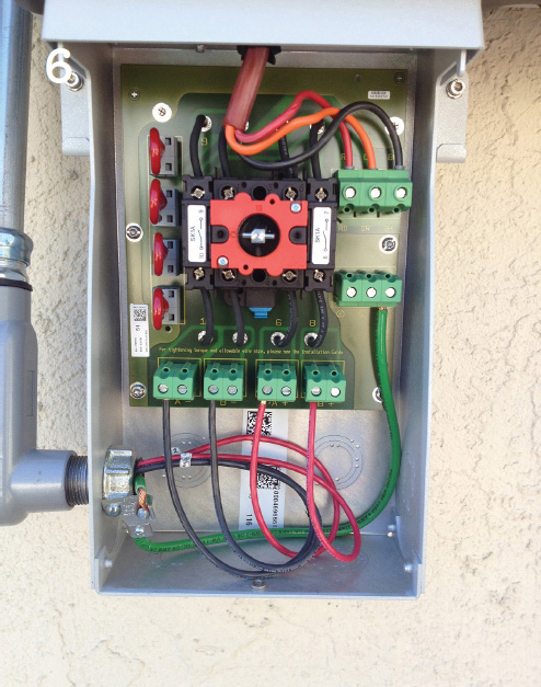
6. The photo shows the inside of the DC disconnect switch box. This switch is ready to be installed between the array modules and the central inverter.
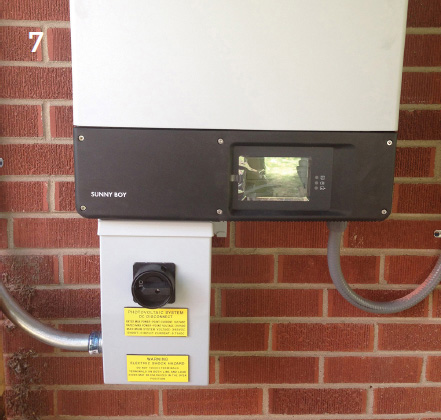
7. In the photo, the DIY installer has just connected and wired a DC disconnect switch under the “Sunny Boy” central inverter.
8. In the photo, we see that the installer has removed the cover plate from the DC disconnect switch and we can see all of the wiring including the 4 (black) leads from the conduit coming from the module string. At the top of the switch box, we can see the red wires leading into the central inverter.
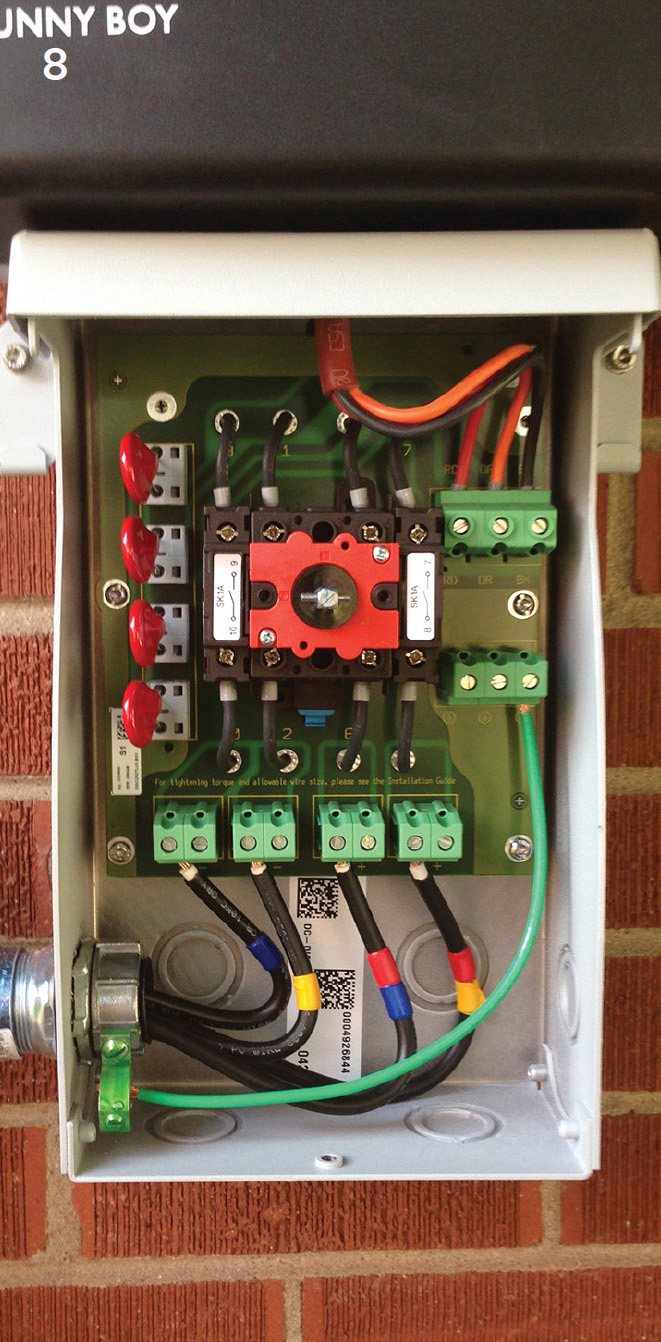
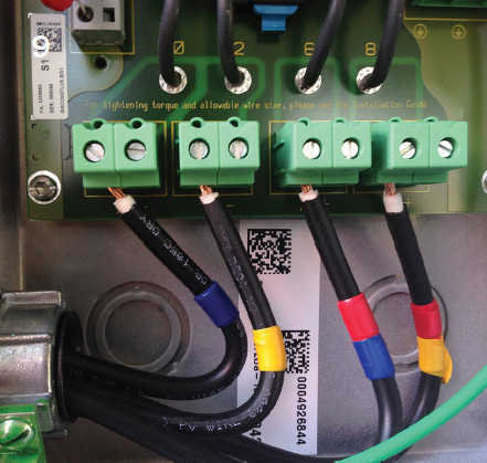
9. The photo is a good close-up of the 4 black wire homeruns entering through the conduit into the box and attached to the 4 green terminals of the DC disconnect switch. A standard good quality straight-blade small screwdriver is used to supply sufficient torque to fasten the homeruns.
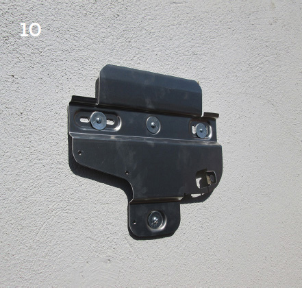
10. In the photo, the installer has just attached an inverter attachment fixture to the wall with an easy disconnect bracket in order to detach the central inverter for service.
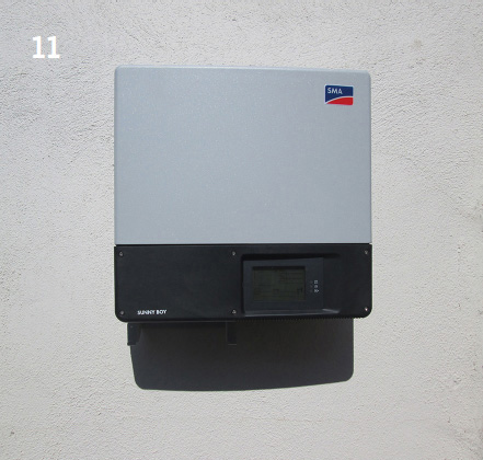
11. In the photo, the inverter is hung on the wall attachment bracket but has not yet been wired.
Micro-inverters are an excellent alternative to central inverters. The basic differences as well as the advantages and disadvantages of each type of inverter are explained in detail in Chapter 4.
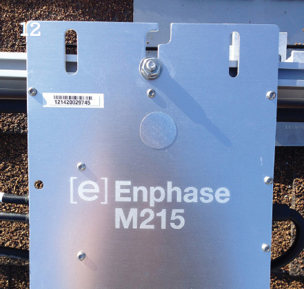
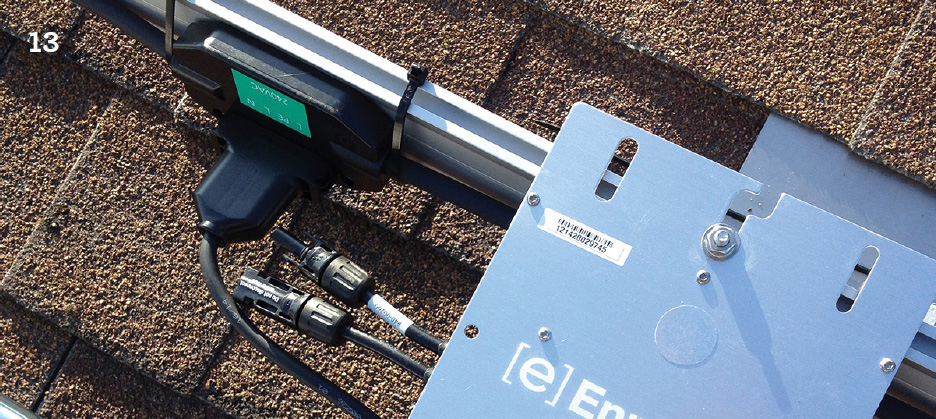
12. This is a close-up photo of a standard Enphase 215 watt micro-inverter being attached to the upper railing before installing the corresponding PV module. This system is being installed with micro-inverters instead of a central inverter. Micro-inverters have been experiencing considerable success since their introduction into the market a few years ago. They have significant technological advantage (among other advantages) over central inverters and these advantages are explained in considerable detail in Chapter 4.
13. The photo shows a small micro-inverter with its 2 leads ready for connection. When micro-inverters are incorporated into each PV panels, you can find them installed on the backside of each module along the upper edge right-hand corner and they are not visible after installation from the side or from above.
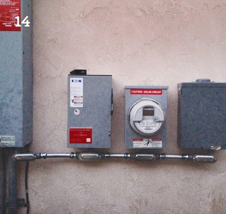
14. In the photo, several electrical devices are being connected in series, including: (L to R) the main service panel, the AC disconnect switch (this is separate from the DC disconnect switch), the photovoltaic system production meter, and the AC combiner panel.
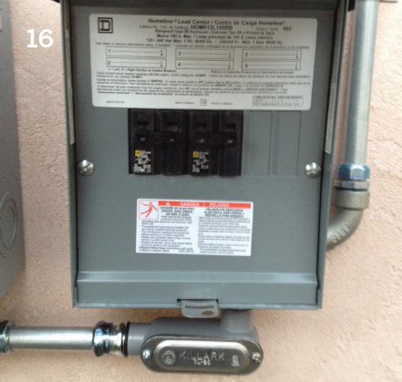
15. The photo shows a close-up shot of the inside of the AC combiner panel with the wiring coming from the PV production meter (through the conduit at the bottom left side of the photo) and, after being combined in the box, the wiring carrying the current exits through the other conduit on the lower right side.

16. This photo shows the AC combiner panel all wired up with its face plate attached.
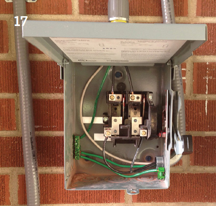
17. The photo shows an AC disconnect switch in the process of being installed.
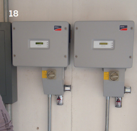
18. The photo shows how the DIY installer crew has just installed an electrical gutter box that combines the output AC lines from the 2 inverters above.
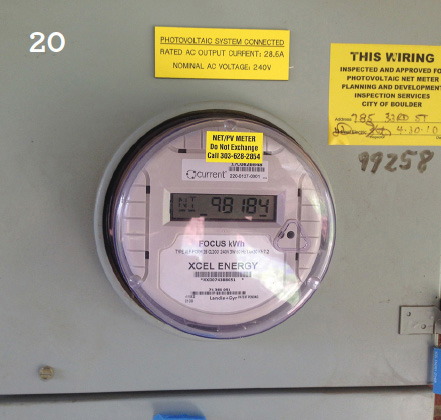
19. The photo shows the next step of the installation, which is the utility net meter. This meter charges the house account with the electricity consumed as received from the utility but it also credits the same account with any excess electricity generated from the PV system that is not used by the home; rather, it is fed back into the grid. The sum of these credits during the month can reduce your net electric utility bill significantly.

20. The above photo shows a large panel combining a utility meter with the main service panel. They can be together in the same panel but are often installed separately. The PV production meter (a separate meter) is then connected to the main service panel.
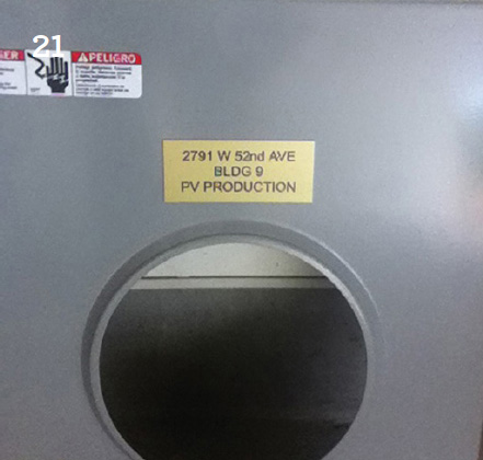
21. The above photo shows a close-up shot of a house waiting to be fitted with a photovoltaic production meter.
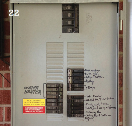
22. The above photo shows that the DIY installer is beginning to install the main service panel and we can see he has started to label some breakers for easy identification of circuits when anyone is inspecting or servicing the main panel. The hand-written labeling identifies which breakers control which circuits or appliances.
23. The above photo shows how the installer has used two different breakers to connect to two separate PV circuits. For example, and for convenience, one breaker might control the lighting of a certain area of the house and the other breaker might protect specific appliances that need electric backup in the event of a grid blackout.

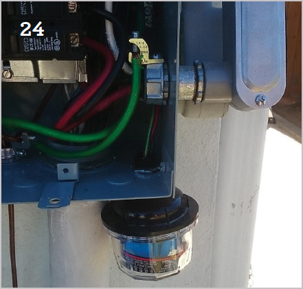
24. This is a close-up photo of a panel that has just had a surge protector installed.
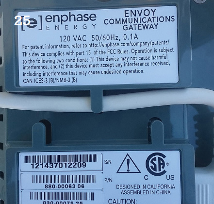
25. In the above photo, we see the DIY-install crew has installed a final optional device known as a "monitoring gateway." This device will permit the homeowner and any service personnel to monitor the production performance of all the individual PV modules in the system and can help locate any defects that might need attention.
26. The above photo shows a relatively simple system where we can see the equipment area with the PV system equipment items installed. From left to right, the DIY-install crew has installed in series the DC disconnect switch that is connected directly into the bottom left of a central inverter; the inverter is then connected to the AC disconnect switch and then to the PV production meter and then it is connected to a combined utility net meter and the main service panel. Note that the PV production meter housing is installed with conduits and wires but the PV meter has not yet been installed.

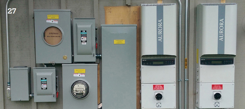
27. The photo shows a second system that is slightly larger than the system shown in the previous photo because it has two central inverters instead of one.
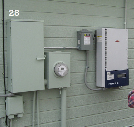
28. The photo shows the setup of the equipment area of a third, relatively simple PV solar system. Most of the same equipment items in the previous two systems are repeated here with only a few exceptions, but in this installation the current will flow from right to left.
