One category of use cases[214] that seems to recur frequently is a variation on the theme of input traffic monitoring or classification, and then taking some sort of triggered action (or actions). The general premise is one of interception or detection of some traffic pattern somewhere in the network—often at the edge or access point—that then results in one or more triggered actions. The action or actions can vary and be quite robust: from as simple as dropping incoming packets or as complex as triggering a query to a radius server or an HTTP redirection. Once those actions are triggered, the system can either return to its original state and simply process traffic as if it had never happened, or alter its actions to do something else either implicitly, or as a consequence of receiving a response from a query such as a radius request. Let’s investigate a few canonical examples to help illustrate how this all might work, starting with the most basic input traffic interception mechanism available: the firewall.
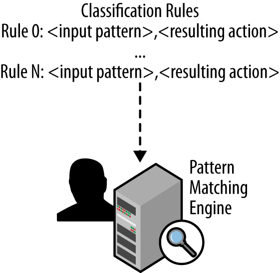
At its heart, a firewall is a system comprised of an input traffic pattern-matching engine populated with a set of classification rules to match input traffic on. Classification rules range in capability from quite simplistic and primitive, to complex regular expressions. In all cases, each classification rule has a corresponding action that is taken by the engine based on a positive match of the classification rule. Thus, the basic function of a firewall is to pattern match input traffic, and take an action. The action, incidentally, can be as input to another rule, which might result in recursive or iterative rule triggers and processing. In effect, the firewall rules become almost their own programming language. This is, in fact, how the most sophisticated firewalls operate today in order to handle the myriad of rules needed to protect and control a modern corporate or service provider network.
As an aside, another similar and often equivalent concept is called access control lists (ACLs). These were the precursors to firewall rules and are often still limited to fairly rudimentary matching rules. The advantage is that most high-performance routing platforms implement the matching logic in hardware and can do the processing at quite high rates, which is something that many firewall devices still cannot do. ACLs are features you might encounter as a feature of most network routing and switching devices, not to mention the most inexpensive wireless routers you have at home.
Let’s investigate how firewall classification rules can be specified, as well as the resulting actions. As mentioned earlier, at their heart, firewall rules are a 2-tuple consisting of {<input pattern>, <action>}. A firewall typically stores the rules in an array format, numbering each rule sequentially. Figure 12-1 illustrates this basic concept.
The match-action rule can be something as simple as “allow all” or “deny from any interface <n>” which would either forward any matching traffic or drop all incoming traffic on interface n, respectively. Or they can be as complex as matching multiple pattern fields within incoming packets, such as filtering on TCP port ranges, “drop from any ipv4 TCP PORT 61000:65095”. Match-action rules can be then chained together to form more complex actions, too. For example, you could jump to a matching rule group if input traffic matched a certain pattern as in, “ACCEPT from 192.168.1.0/24 to Interface eth0 –j GOOD-DMZ”. In that example, you would jump to another set of rules defined in the “GOOD-DMZ” rule group. To put these concepts together, let’s look at some sample output from the Mac OS X pfctl firewall:
Firewall
#
# anchor ruleset for the Adaptive Firewall
# anchor name: 400.AdaptiveFirewall
# see afctl(8), pfctl(8), pf.conf(5)
#
block in quick from 122.110.1.78 to any
In this example, traffic from a specific host (122.110.1.78) is explicitly blocked. This is achieved by specifying an explicit classifier match pattern in the last line. If the firewall matches input traffic coming from that IPv4 source address, the resulting action is to block or discard the traffic.
As mentioned, rules can be chained to form more complex rule sets that give network operators the ability to narrow down traffic patterns based on input conditions, or to allow subsequent match rules to be fired only based on certain, possibly dynamic, input conditions to exist. For example, input traffic rate limiting or input traffic shaping, as it’s more well known, is really an action function triggered by receiving traffic above a certain threshold. The resulting action is to drop or sometimes selectively drop (i.e., shape), input traffic matching those criteria.
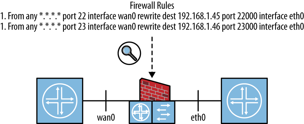
It should be noted that firewall pattern matching can be quite sophisticated. Until now, the discussion has centered on simple rules such as “allow” or “drop,” but there are other possibilities, too, such as “rewrite” which instructs the firewall to modify parts of the packet upon matching. For example, it is possible to do network port mapping within the firewall. That is, when a pattern is matched, say, receiving a packet from any host on any externally facing interface, it translates some port to one that is internally used. This is a function that can be used to map a variety of services accessible externally to internal hosts behind a Network Address Translation (NAT) gateway. For example, you could define a rule set such as:
From any *.*.*.* port 22 interface wan0 rewrite dest 192.168.1.45 port 22000
From any *.*.*.* port 23 interface wan0 rewrite dest 192.168.1.46 port 23000
The first rule would match traffic from any host that arrives on the device’s “wan” or externally facing interface with IPv4 port 22 and rewrite the ipv4 destination address to 192.168.1.45 and the port to 22000. This could be used to map the normal secure shell (SSH) traffic that comes to this network to a special gateway host that is configured as the server with special authentication capabilities. The second rule similarly rewrites traffic coming to this device with port 23 to port 23000 and sends it to host 192.168.1.46. This effectively rewrites that traffic stream’s port to a special incoming one and sends it to another special host. Figure 12-2 illustrates how these input rules could be applied to a firewall device.
So far, the discussion has been about the capabilities of just about any firewall you will encounter in a network today. Traditionally, these functions were implemented in system software that ran on physical devices that were dedicated to that specific function. In fact, many of these devices were built with hardware that was optimized for these functions, including optimized input pattern matching hardware interfaces and switching fabrics that connected the input port(s) to the output port(s) of the firewall.
So the question is: why virtualize this function? The answer is simple: flexibility and cost. Firstly, the flexibility of taking the software out of a custom designed device and running it on commodity hardware—let’s call it Intel x86—is very appealing. It allows network operators to have a variety of options about how they assemble their network, or more importantly, change it later. The other option they have is to also shut that software off and run something else in its place! If you imagine the requirements to physically move a firewall—both physical and those of the operational support system (OSS)—it should be clear that it is cheaper and far faster to move the firewall software rather than its hardware. The flexibility of placement also lends itself to service chaining, as we discussed earlier in Chapter 7, as a potential use for chaining together physical and virtual services; a firewall, virtual or otherwise, is considered a network service.
It should be noted that running commodity hardware is not a new idea, and in fact, many of the firewall devices that you will encounter are and have been running on x86-based devices for quite some time. That is, the control plane software (the software responsible for maintaining the rule sets and the general control configuration, user interface, etc.) has been executing on an x86 CPU for quite some time. That CPU did not actually process user packets; instead, special switch fabrics and purpose-built port processors were created to connect the input and output ports, with special pattern matching hardware that was then essentially statically programed to look for specific patterns and ultimately forward, drop, or modify a packet. The instructions (i.e., rules) were programmed in that hardware by the system software or control plane that ran on the CPU. In effect, you had a split system with the brains residing in the x86 CPU, and the brawn doing the heavy lifting of the packets down in purpose-built hardware.
What is new in the modern hardware scene is that off-the-shelf network interfaces that were once woefully inadequate are now approaching the packet processing performance characteristic of custom-designed hardware. Furthermore, modern CPUs can handle a great deal of pattern matching capabilities, especially when optimized for packet processing such as been done by the Intel Data Plane Development Kit (DPDK) system.
Given the great improvements in packet processing with cheap, off-the-shelf hardware, we now can not only imagine but actually run virtual firewall instances. While not at 100% the same processing performance as dedicateed hardware, when you attach the virtual firewall instance to a single CPU and network interface, you can attach the problem using a divide-and-conquer approach and achieve nominally the same approach, albeit with more moving parts to manage. That is, if you spread a copy of the virtual firewall instance to a number of x86 CPUs, all with their own network interfaces, and appropriately steer input traffic to them to handle a subset of the overall input traffic, you have effectively sliced the input traffic workload among many devices rather than relying on one big (and expensive) piece of custom hardware.
This leads to the second advantage: price. There is a break-even point for spreading workloads across commodity hardware that differs depending on the actual product in question, so let’s not attempt a guess at the actual point here. However, since many network operators are moving to generic x86-based data centers for other computational tasks, one can imagine that they have spare capacity available for firewall processing. Being able to use the same hardware for multiple purposes is a clear optimization of the overall equipment cost.
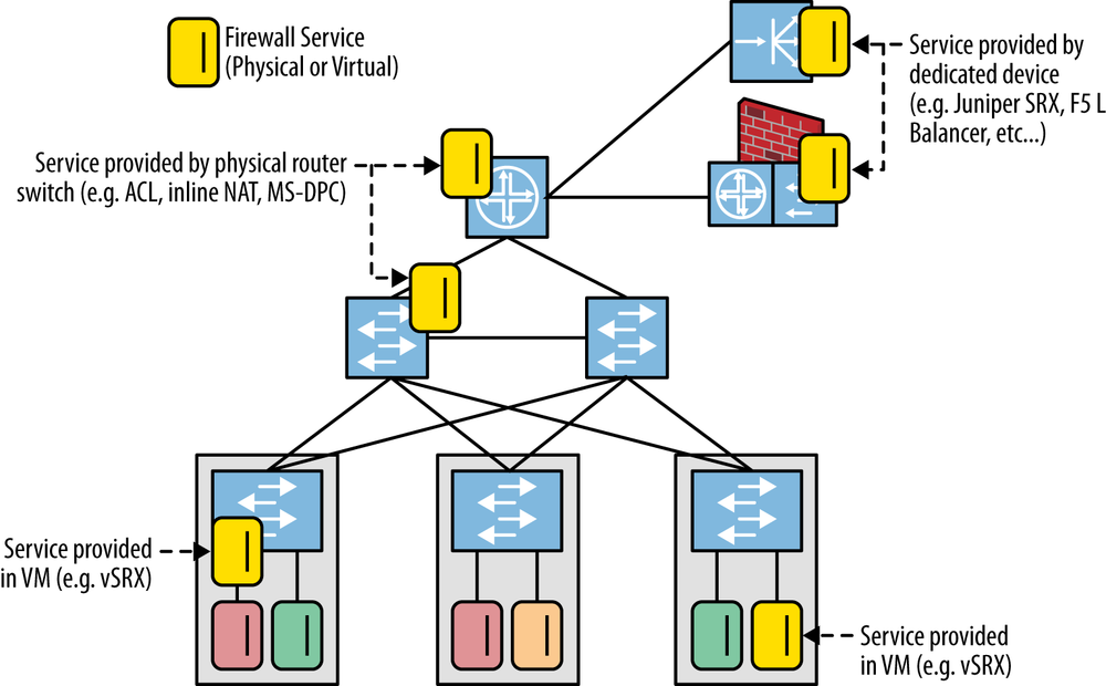
Figure 12-3 demonstrates how this scenario could be set up. Notice the mixture of real and virtual firewall services deployed in the network. One note is that the operator must understand that the virtual machine’s placement within the network is critical, as is its connection to the actual network, because this will affect its packet processing rate, as well as the delay the packets it processes experience. For example, poor placement of the virtual machine, geographically, will result in additional hops of forwarding, thereby adding delay to the packet’s journey through the network. Also, placement of a virtual firewall on a physical system that is already well-loaded, either in terms of CPU processing or packet processing on its input interfaces, can also result in delay or even packet loss.
A final twist on the virtualization of firewall services is to add centralized control of the firewall service itself. This can be implemented as a combination of centralized control of not only the service (and the virtual machine in which it lives), but also the actual firewall rules that are used to drive the pattern matching function of the firewall. If you look at the instances of firewalls both virtual and real in the previous example, you can imagine how a centralized controller could control and orchestrate the network of firewalls from a centralized point, as well as from a distributed approach. In the case of the former, a network operator would have the advantage of a single point of control (logically centralized) from which to enact changes to the configuration state of any firewall in the network. In the second decentralized case, the operator would have to first understand which control point controlled which subset of firewalls before then adjusting the configuration.
Network Access Control (NAC) might be considered a derivative or simplified case of firewall as a service. NAC is commonly achieved through the use of switch/router Access Control Lists (typical of fixed port ownership relationships like those exhibited in an Enterprise VPN environment) and/or policy-based solutions hinging on radius/diameter interaction between a policy server and the switch/router (typical of per-subscriber sessions on shared access infrastructure).
These solutions have their limitations. Critically, most implementations allow for a pre-compiled (i.e., statically programmed) ACL that is less suitable for a dynamic (fast-changing) environment. That is, the rules are pushed down to every switch in a network via a provisioning system, effectively reconfiguring every switch. For most devices, this is rather time-consuming because configuration operations take on the order of minutes to tens of minutes. Some early adopters of SDN technology want to use the more dynamic nature of SDN as a NAC replacement strategy.
To illustrate Network Access Control with a centralized SDN controller, let’s use an OpenFlow-based example. It should be noted that you can use other mechanisms to implement this use case, but OpenFlow has characteristics that make it particularly appealing for solving this problem, such as the completeness of the solution compared to alternatives (at the time this book was written). Also in particular, OpenFlow allows matching across a wide swath of the datagram header, while alternatives like BGP flowspec (IETF RFC5575), though more dynamic than the static ACL, lack this range and are currently limited in universal address family support and IP prefix related filters.[215] Further, if the vendor implementation of OpenFlow rules does not reuse the ACL or firewall filter structures effectively, implementing OpenFlow as a true forwarding table entry rather than a feature phase of forwarding, you can avoid the compilation dilemma of typical ACLs. That is, you can achieve rather painless and dynamic adjustment of NAC rules.
Of course, this would normally relegate the privilege of first lookup to the OpenFlow table as a tradeoff.[216] In cases where the implementation does not reuse the ACL or firewall structures, the implementation will suffer from a variety of performance and scalability penalties. In particular, a naïve implementation will attempt to literally program each OpenFlow rule verbatim without the benefit of rule compilation. Rule compilation effectively compresses and optimizes the rules down to their salient components and effectively shrinks down the number and complexity of the actual rules used to program the hardware. This not only means less space needed to store the rules in hardware, but potentially more optimal processing by avoiding unnecessary look-ups or recycling of rules.
Using the central controller, we will attempt to address what at first seems like a relatively simple problem. That is, constraining the use of the corporate IMS/SIP subsystems to approved desk or wireless IP phones and restricting access to the corporate network to registered devices in a rapidly evolving bring-your-own-device (BYOD) environment.
Let’s preface the discussion first with some background information. Though the IT department originally considered using 802.1X manufacturer identification, the truth is that not all devices support 802.1X, and the brand of IP phone selected for their offices falls into this category. Furthermore, after examining a multivendor solution, the IT department also noticed a number of incompatibilities between devices. So in an effort to not get hemmed in to a single vendor for their enterprise Ethernet switches, this example was constructed.
The building blocks of the solution are illustrated in Figure 12-4. The approach of the
solution is straightforward and involves the use of a simple radius
glue-logic application that resides above an OpenFlow controller to verify
the registration of the each device entering the network. The capability
of an OpenFlow (v1.0) enabled device (i.e., the access switches) is only
required to match traffic based on source MAC address and perform
PACKET_IN and PACKET_OUT functions.
Switches must also be able to punt packets matching a rule to the
controller, or shunt the traffic to a VLAN. It needs to be noted that the
underlying network uses IP/MPLS forwarding to provide layer 2/IP
infrastructure for packet delivery from edge to edge.
The combination functions as an OpenFlow hybrid network.[217] The connection between the two functional sides of the hybrid can be made using an Integrated Route-Bridge instance in the OpenFlow domain and OpenFlow NORMAL functionality, or by using a logical port structure (e.g., logical tunnel) that has ends in the OpenFlow domain and a layer 3 routing instance (a RIB association) as the incoming/outgoing port in OpenFlow rules.
When a client device sends its first packet, a lookup is done to see
if a rule matching that specific source MAC exists already in the switch.
If this fails, the packet is sent using a PACKET_IN
operation to the active controller. This same controller is responsible
for creating rules for the virtual switch inside the access switch. This
switch is also where the controller delegates the ingress port.
In order to avoid wasting cycles in the authentication glue logic on
the controller, a cache is maintained of recently authorized flows on that
same controller. This is the case even if the flows are inactive on a
particular switch. Since the IT network users are expected to be mobile,
they conceivably could change wireless access points resulting in a
potential change in their association with a physical access point at the
edge of the network. If a rule exists, the controller will populate the
switch with that rule and perform PACKET_OUT, which
will return the original packet to the pipeline for forwarding.
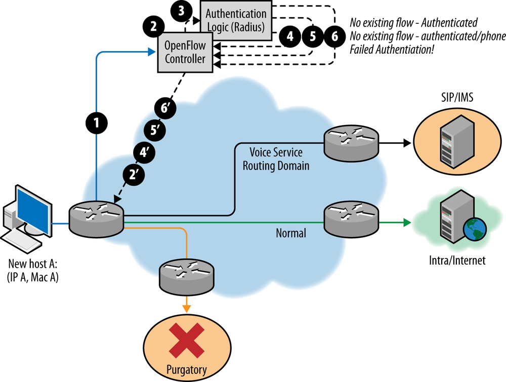
The authentication lookup can result in one of the following:
- AUTHENTICATED_MAC_PHONE
The MAC is a registered MAC and it is an approved phone type for the IMS/SIP subsystem. In this case, the flow modification sent to the switch will indicate that all traffic matching that MAC will be allowed to access the IMS/SIP region of the network. This would be expressed simply in an outgoing port action for that match of the logical port that connects to that infrastructure (be it layer 2 or layer 3). Depending on the underlying network plumbing (for example, if a logical tunnel doesn’t represent this access, but a shared layer 3 construct and the NORMAL action does) the rule may need further embellishment to specifically match on the IP prefix(es) assigned to the IMS/SIP system as destination IP.
- AUTHENTICATED_MAC
The MAC is a registered MAC, but not a phone. In this case, the flow modification sent to the switch will indicate that all traffic matching that MAC will be allowed to access the intra/internet regions of the network. This could be done by matching a fairly generic flow rule based on the source MAC with an outgoing port connected to that region of the network, with similar caveats about the underlying plumbing (in the case of a shared layer 3 construct and NORMAL operation, additional match rules would explicitly deny access to NORMAL for flows with a destination IP in the prefix of the SIP/IMS region).
- AUTHENTICATION_FAILED
The MAC isn’t a registered MAC. In this case, the flow modification sent to the switch will indicate a rule that matches all traffic from that MAC with an outgoing port that represents the PURGATORY region of the network (this is the customer’s own colloquialism for either DROP or a network on which a registration server exists0.
There are potential modifications or problems unaddressed by this example that will lead to some refinements. To this point, we’ve only exhibited some minimal policy dynamics that were hard to express with a traditional access control list on the access switch. [218] In typical networks, it is common to find more complex ACLs.
The limits to the model, and where we depart from simple Network Access Control, are seen when supporting any authenticated MAC address. This opens up the realm of possibilities from just VoIP devices to any computing device that could be attached to the corporate IT network. Further complicating the simple scenario might be treating the traffic from both a desk phone and the laptop softphone or media application with higher quality of service (e.g., by marking the packets in the flow with a special DiffServ Code Point (DSCP) that results in that traffic being honored as a higher class of service in infrastructure forwarding devices).[219]
The unfortunate truth is that a simple flow-matching rule won’t work here for a variety of reasons. First, most media applications use RTP in UDP encapsulations. These in turn use amorphous ports for the sender and receiver once flows are established. The flows are established by a separate control protocol. This is typically SIP, but in some evolving services, the control channel may be encrypted, potentially making signature detection much less efficient. The alternative of not using the firewall at all and simply treating all unknown UDP packets preferentially is considered too easy to exploit by end users. At this point we are going to need the services found traditionally in the firewall to detect these flows through an application signature, requiring the firewall to monitor a certain percentage of traffic or a flow sample that can then be used for detection of an application signature.
This approach has two potential solutions. First, build the
firewall-like application on top of the controller,[220] or second, identify the traffic using a firewall (real or
virtual) somewhere in the flow. This application would then perform
appropriate QoS treatment. To build the application on top of the OpenFlow
controller, you would have to use the PACKET_IN
capability of the OpenFlow switch/controller combination or create a tap
rule.
To avoid overloading the firewall application, you can use proactive
flow rules limiting the PACKET_IN traffic to unknown
UDP ports. In this case, you have to be both careful and aware of the
changes in this mechanism in the different versions of OpenFlow. If our
controller and switch don’t support OpenFlow 1.3, then the
PACKET_IN mechanism has to use the TCP control session
between controller and agent. Because the agent is maintaining the
sequence number for the TCP session, it’s difficult (if not impossible) to
remove it from the packet path[221] or do any sort of performance enhancement for the packet
processing, making this approach to a firewall application infeasible. It
should be noted that with the advent of OpenFlow 1.3, a UDP flow can be
used for PACKET_IN, which could make the application on
top of the controller more palatable.[222]
Another way to build an application on top of the controller is to create a tap rule that mirrors the traffic to the firewall app. The rule will duplicate outputs to two separate ports as the action on matching the unknown UDP flow.[223] In this scenario, the application would sink/drop the matching traffic and send back flow modifications via the controller API when the application senses the media applications and identifies the ports for specific flows.
An example of this approach is seen in the FortNox[224]/FRESCO[225] combination (SRI), which combines a conflict mitigation module (making sure flow rules from multiple sources follow policy) and a scripting/development framework that can allow plug-in type modules to reflect/scan/affect traffic forwarding.
Since the appeal of the on-top and the tap solutions may be limited, you could try an alternative solution that uses an in-line firewall but manipulates the UDP traffic in a way that reduces the burden on the firewall (Figure 12-5).
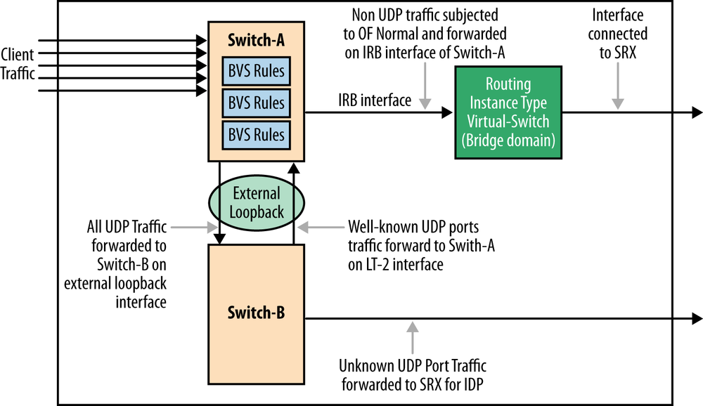
The particulars of the sample design include:
There is one IRB (or logical tunnel) interface for forwarding all “non-UDP traffic” to routing instance using OpenFlow action “Normal”. This IRB (or logical tunnel) interface is configured as an OF port in OpenFlow configuration stanza(s) on the switch/router.
Two logical switching constructs are used to create a loop for the unknown UDP traffic to be treated (by the firewall) for QoS. The logical switches allow for some rule partitioning for administrative reasons. The external loopback could be created physically via the firewall (versus between the logical switches). There was some thinking that the switch port resource was less expensive than the firewall resource at the time of this design.
A port-to-port OpenFlow rule in Switch B pushes all traffic returning from the firewall, including the (potentially) treated unknown UDP through the loopback toward Switch-A. A port-to-port rule in Switch A then pushes the traffic from the loopback to the IRB (and a static associated QoS policy).
Both the firewall application on the controller and in line within the firewall will have a common optimization goal: minimize the traffic sent through the firewall. This is based on the assumption that the firewall resource introduces additional hardware or operational costs that are defrayed by managing the scale of the solution. Once a specific media flow, including the amorphous ports, has been identified by the application, a feedback mechanism that puts in place a specific flow rule should pipeline this traffic to the egress port.
However, in our OpenFlow example, QoS treatment requires the controller/switch to support either the optional SET QUEUE primitive as mentioned in previous footnote with an associated dependency on the support of messaging to discover port queue assignments and properties, or the optional ability to set DSCP of a packet directly. The latter will rely on the externally configured QoS policy on the egress port. The minimum version required for either of these capabilities is OpenFlow 1.2.
The ability to create feedback between network elements, services, and a logical point in the network is critical in order to optimize the use of network resources, and it is fundamental to many examples, regardless of the SDN control scheme or protocol used. More to the point, although we have used an OpenFlow example in this section, it is fundamental to enable and facilitate the feedback loop between network control and network resources. Such feedback loop principles are discussed in the example that follows.
The Intrusion Detection/Threat Mitigation System (IDS) illustrated in Figure 12-6 uses a similar strategy to minimize the load on the network service element (a real or virtual IDS system) by deploying an interior perimeter of rules:
Generic rules that do flow forwarding based on IP source and destination prefixes.
More granular (i.e., longer match and higher preference) for specific and approved flows between these sources and destinations.
A rule handling flow misses (
UNKNOWNtraffic) with a rule that will create a copy of the packet using an action set like that of the tap application, and forward a miss to the IDS. The IDS software can be doing device profiling flow signature matching and other tasks.Depending on the outcome of the analysis, a specific flow entry allowing passage of the traffic can be installed via an API call to the OpenFlow controller at the interception point or a specific flow entry. The action would be to
DROPthe flow. This rule can be installed on the ingress switch(es).
In either case, the flow will not continue to traverse the IDS/UTM.
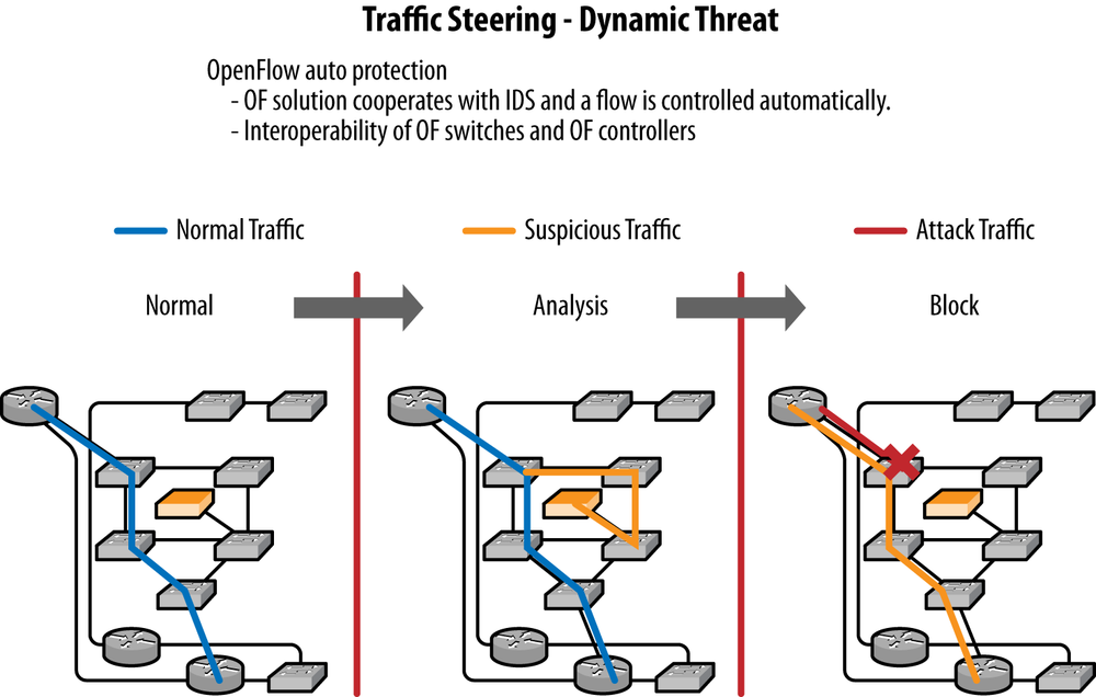
Optimally, this feedback loop would create a learning system wherever possible. It needs to do this so that default rules and policies are incremented to capture these learned behaviors. Some of the more logic-driven aspects of intrusion detection and threat mitigation such as the logic that tracks changes in expected behavior or profiles—like when a known print device begins to initiate flows associated with a compute device, up to and including network mapping or port scanning—may be too difficult to capture in a small set of rules and thus defeat learning. However, some degree of learning could be expected with this particular example.
If you consider service chaining as an SDN application,[226] not only will feedback loop optimizations be applicable, but also triggered behaviors (e.g., based on DPI inspection and policy rules) will make flow paths even more dynamic. This further limits the capability to learn a larger permanent flow rule set.
Other examples of such a feedback loop abound, and in particular, the recently added 3GPP Traffic Direction Function (TDF) in the mobile domain, as shown in Figure 12-7, shows similar functionality.
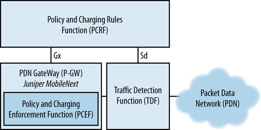
The TDF (normally a DPI device) is instructed by the PCRF (via the Sd interface) to look for specific application flows, and the TDF uses the same interface to alert the PCRF when they are detected. In turn, the PCRF may then instruct the PCEF to install a change rule using the Gx interface.
This chapter has demonstrated use cases for ingress traffic detection. Its examples showed how input traffic could be classified using simple firewall rules or access control lists (ACLs), and corresponding actions taken. These included the canonical firewall device and the virtualized firewall device. It then expanded from these simplified examples to demonstrate how the Network Access Control (NAC) protocol could be replaced using two key tenants of SDN: logically centralized control and ingress traffic detection. It then demonstrated how this could be further adapted to implement dynamic threat mitigation. Along the way, we discussed why it is important to enable another key tenet of software-defined networks: the application-controller feedback loop, and specifically, why certain optimizations could not be achieved without it.
[214] These examples are not meant to be “cookbooks” (each would spawn its own book at an appropriate/usable level of detail for that function), but rather a greater illustration of the use of SDN in basic traffic monitoring application(s).
[215] See prior chapter for references that extend flowspec to make it more usable for this and other purposes.
[216] The authors have seen customer RFP requests to treat OpenFlow rules as if they were dynamic ACLs, maintaining “first forwarding lookup” in the default IP forwarding tables. But, to our knowledge, this has not been implemented.
[217] The operation of the network edge as an OpenFlow hybrid is optional. One could argue that NAC is implicit in a pure OpenFlow network.
[218] SDN is also used in this example to normalize the deployment of access control and to deploy in a vendor-independent manner—free of the ACL syntax/semantics specific to any particular vendor (which is one of the fundamental appeals of the use of standardized SDN protocols as provisioning tools).
[219] There are other options when using OpenFlow (to achieve QoS treatment on a node-by-node basis—assuming all the nodes are controlled by OpenFlow). For example, the “optional” Set-Queue action in OpenFlow could assign the packet to a queue, assuming that the switch supports queue and queue property discovery (configuration of the queue parameters MIN/MAX rates and an EXPERIMENTER field to communicate information are supported in OpenFlow version 1.2 and beyond). This could be combined with the “optional” Meter structure of OpenFlow 1.3 to affect many different QoS actions. However, because these are recent, optional, and the actual queue configuration is still separate from the OpenFlow wire protocol, a simpler example is used that relies on external (non-OpenFlow) QoS treatment.
[220] “On top” does not imply the firewall application Virtual Machine is co-resident with the controller, since the northbound API for OpenFlow controllers is normally RESTful. But you do need to be mindful of any latency pushing the packet from the controller to the application may introduce and that impact on the apparent “responsiveness” of the application. For this application, if the media flow is a video (particularly a video chat) the flow is expected to be large and of reasonable length (assuming the function is more like a meeting and average meeting times are measured in 15 minute increments). If the media flows were all VoIP, the responsiveness of the application may be more critical, since the flow length may be relatively short (by the time the flow entries are in place to enable QOS treatment, the flow may have ceased).
[221] This pathway is the traditional “slow” path for routers and switches (lower packet throughput, more CPU usage for the agent process on the switch/router).
[222] At the time this book was written, there is little (if any)
experience with using the UDP-based PACKET_IN
functionality.
[223] Incidentally, the Virtual Tap application is a specific application for an OpenFlow controller that uses this same mechanism to mirror traffic to a monitoring device.
[226] We have been dealing with NAC and its derivative examples in this chapter, but have migrated the example into the territory of service virtualization, even though we haven’t explicitly shown a chain.