There has been a proliferation of small studios in basements, barns, garages, and other locations in and around private residences. Some of these are built by the members of new bands who figure that such a facility will help them develop their musical techniques and enable them to record demonstrations and other records at leisure without high studio charges. Some are built by advanced audiophiles who have become jaded to further improvements in the living room hi-fi, but are challenged by recording techniques. Such a private studio is a logical next step after experimenting with multichannel recording with a four-track consumer type tape recorder. This type of experimentation soon runs headlong into the frustrations of household noise, limitations in the number of tracks, and problems created by haphazard, temporary lash-ups.
Some may look to a private recording studio as a stepping stone to getting into professional recording. As far as gaining experience is concerned, excellent, but if renting the studio to musical groups is contemplated, beware. Most communities look with disfavor on commercial activities in residential areas. Construction of the studio to be described in this chapter definitely requires a building permit and the usage planned for the facility is sure to come up. Now that this point has been made, the studio has limited commercial possibilities. The greater the experience one has, the greater the emphasis on that word limited.
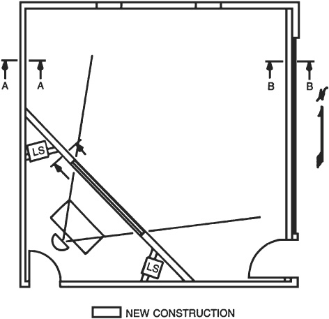
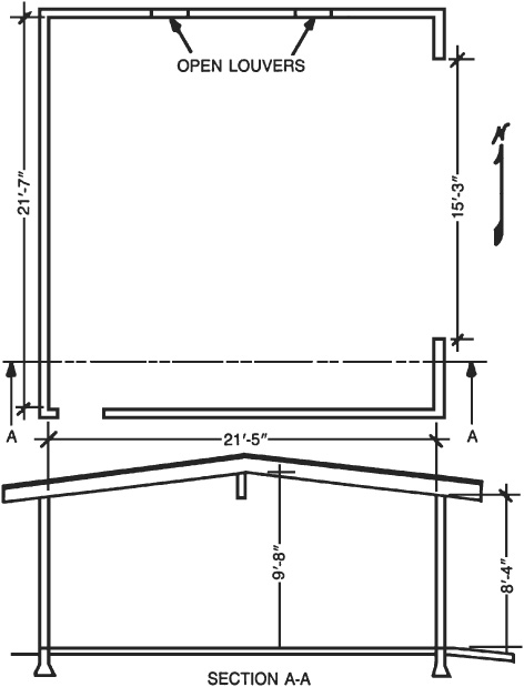
The two-car garage to be converted into a multitrack studio is described in Fig. 12.1. It is almost square and is covered with a simple A-roof. The open ventilation louvers in the north wall, a 15-foot 3-inch overhead door opening in the east wall, and a small rear door in the south wall emphasize that the garage is just a wide open shell with unfinished walls inside.
FIGURE 12.1 Plan and sectional views of garage before its conversion to a multitrack recording studio.
The first step is to make the garage into a tight structure and to make provisions for a monitor control room. Figure 12.2 shows one way of distributing the 464 square feet of total area between the studio and control room. This gives a studio floor area of 352 square feet and a control room area of only 85 square feet. The studio size is over twice the minimum prescribed volume of 1500 cubic feet but the control room is only about half the minimum.
FIGURE 12.2 Plan for conversion of garage of Fig. 12.1 to a multitrack recording studio.
This may be sufficient incentive to drive the recording technician to using high quality headphones instead of monitor loudspeakers. The fact is that with a square garage, any location for the control room other than a corner results in serious degrading of studio space. The floor plan of Fig. 12.2 favors the studio. Perhaps that demo record may have greater impact with a reasonable studio and operator wearing headphones than a tiny studio with its poor separation and more accurate monitoring room.
The use of high quality headphones,12 if not a first choice, is at least a viable alternative for listening critically in acoustically difficult situations. They are being improved much faster than monitoring loudspeakers.
The louver ventilators in the north wall are abandoned and the opening framed in and covered to conform to the other external walls. The overhead door probably should be retained for external appearance, although the bulky hardware may be removed and stored for possible future use. A new frame closes off the 15-foot 3-inch door opening. A door (3 feet wide to accommodate instruments) is cut in the east wall for access to the studio. This should be a 1¾-inch solid core door and well weatherstripped. The sound lock corridor in this case is the great outdoors. The existing doorway in the south wall serves the control room, but the hollow core door is replaced by a 1¾-inch solid core door and also weatherstripped.
The internal wall and ceiling surfaces are covered with  -inch gypsum board as shown in Fig. 12.3. Great care should be exercised to assure tightness as this layer is the chief assurance against complaints from the neighbors. This requires filling of all cracks and taping of all joints as well as a liberal use of nonhardening acoustical sealant at all intersections of surfaces. This drywall layer goes in the control room as well as the studio. The diagonal wall between the studio and the control room has a -inch gypsum board on each side as shown in Fig. 12.3, Section C-C.
FIGURE 12.3 Wall construction details in converted garage studio. Sections refer to Fig. 12.2.
The conversion of this garage to a studio is fraught with compromises. The result will be midway between the living room and a first class studio. The wall between the studio and control room is such that studio sounds will sometimes be heard in the control room without benefit of amplifiers and loudspeakers. Neighbors can probably hear a lively number being played in the studio, but hopefully at a low enough level that they will not call the police.
Unless the two single doors are made impervious to sound, there is little advantage in strengthening the walls. A good, tight wall such as shown in Section C-C of Fig. 12.3 has an STC rating of 30 to 35 and the stucco plaster of Section A-A is only slightly better. Great care must be exercised in weatherstripping doors to get STC 30. The 3½ inches of insulation fill indicated in all sections of Fig. 12.3 contributes very little (about 2 dB) to the transmission loss. It does help some in discouraging cavity resonances. Because of its minor effect, it could be omitted if the budget is very tight.
Multitrack recording requires acoustical separation of the sounds of instruments or groups in instruments which are recorded on separate tracks. One way of achieving such separation is to physically separate the sources and place a microphone close to each source. Space is limited in this studio, but this logical and desired approach is more effective in an acoustically dead space than in a live one. There are other ways separation can be achieved, such as the use of microphone directivity, or baffles.
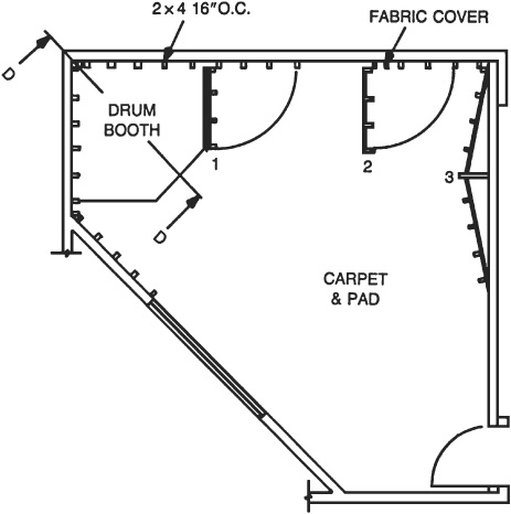
Musician reaction places a limit on the deadness of such a studio because they must hear themselves and other musicians to play effectively. The studio of Fig. 12.4 has been made as dead as practical to allow the achievement of reasonable track separation, even though the space is small for this type of recording.
FIGURE 12.4 Studio details in garage converted to multitrack studio. Swinging doors 1 and 2 serve as baffles between instruments. Element 3 on east wall helps to absorb very low frequencies.
Heavy carpet and pad are applied to the entire concrete floor except the drum booth area. This opposes the sloping, reflective ceiling surfaces which are bare gypsum board. Reflections from this ceiling could contribute to leakage between tracks. If this proves to be a limiting factor, absorbent material could be applied to critical areas of the ceiling.
Much of the wall is faced with 4 inches of 703 semirigid glass fiber boards. These glass fiber panels are inserted between vertical 2 × 4s which are mounted against the gypsum board wall covering and run from floor to ceiling. Figure 12.4 shows the 2 × 4s spaced 16 inches center to center, lined up with the studs of the exterior wall to which they are nailed. After the glass fiber is installed between these inner studs, a fabric cover is stretched over all, tacked in place, and finished strips nailed on the edge of each 2 × 4 to complete the floor to ceiling job. The south half of the east wall and the south wall are left reflective to provide an area in the southeast corner of the studio, near the door, which would have somewhat brighter acoustics than the other areas near absorptive walls. Such localized acoustics can be of great help in instrument placement.
On the north wall are two swinging panels 4 feet wide running from an inch above the carpet to a height of 6 feet to 8 feet. These panels are framed of 2 × 4s with ¾-inch particleboard or plywood backs for strength holding 4 inches of 703 glass fiber covered with fabric like the walls. The back of panel 1 in Fig. 12.4 in open position presents the drummer with his only reflective surface apart from the floor. The space between swinging panels 1 and 2 can be occupied by one instrumentalist (or group) while the space between panel 2 and the east wall can be occupied by a second. Others will have to be positioned in the open area.
On the east wall the same 2 × 4 framing filled with 4 inches of 703 is followed except that here a space behind is provided to augment absorption in the very low frequencies (element 3). At these frequencies the sound penetrates the 4 inches of glass fiber, causing the ¾-inch plywood or particleboard to vibrate as a diaphragm, absorbing sound in the process. It may be found that the instrumentalist in space 1 is too close to the high level drum sound. It would be quite acceptable to move the low frequency element to the north wall and the instrument alcoves 1 and 2 to the east wall if this would meet separation needs better. Such a move would increase the distance between instrumentalists (and their microphones) and the drum kit. Barriers 1 and 2 would provide separation only between instruments, not between instruments and drums unless more complicated double-hinged panels were installed.
The corner area for the drum booth is indicated in Fig. 12.4. The concrete floor of the booth is left bare under the drums to give the desired effect. Another reflective surface for the benefit of the drummer is the surface of swinging panel 1. Apart from these, all surfaces around the booth are highly absorptive to contain the drum sounds and thus improve separation from the sounds of other instruments.
Without adequate separation the advantages of multitrack recording disappear. There is general agreement on two points:
• That sounds from the drum kit are hard to contain.
• A good drum sound is basic to any group.
This is justification for doing something extra for the drummer, even in a budget facility such as this. It would be nice if we could do the same for the vocalist.
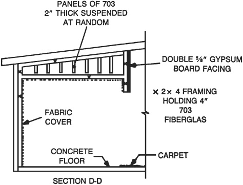
Leaving the bare ceiling over the drum booth would defeat the whole purpose of the booth. Drum sounds must be absorbed rather than allowed to float over the entire area. A canopy of 2 × 4 framing is dropped down from the ceiling to a point 6 feet above the concrete floor as shown in Fig. 12.5. The shape of this canopy follows the general drum booth front edge shown in Fig. 12.4.
FIGURE 12.5 Section of Fig. 12.4 through the drum booth. All drum booth surfaces except the concrete floor are highly absorbent to contain drum sounds.
The face of the canopy toward the studio is covered with a double layer of -inch gypsum board, but the inside of the entire 2 × 4 framing on 16-inch centers is left open to receive 4 inches of 703 glass fiberboard.
A fabric cover is then applied and held in place with finished strips nailed to the 2 × 4s. This 4 inches of 703 treatment faces the drummer on all sides including walls, underside of canopy, and inside of canopy lip. The construction leaves an attic between the canopy ceiling of 4 inches of 703 and the 4 inches of 703 affixed to the uppermost ceiling gypsum board. Because drums have a hefty low frequency content, the attic can be made into an effective absorber for very low frequencies, frequencies lower than the 4 inches of 703 can handle. The term basstrap has been applied to such absorbers. Such a catchy term, which seems only to confuse the populace, is not used in this book, at least until trebletrap is accepted to describe the acoustical effect of carpet. Low frequency absorbers, however, do come in varying degrees of lowness. The 4 inches of 703 is essentially a perfect absorber down to 125 Hz and its absorbing effectiveness decreases as frequency is lowered. For this drum booth attic, a trick of the builders of early anechoic, free-field chambers or dead rooms is used. This is the hanging of spaced absorbing panels to extend the useful low frequency range of the room. The spacings of the panels of 2-inch thickness 703 may be random rather than following meticulous rules used in those early days.
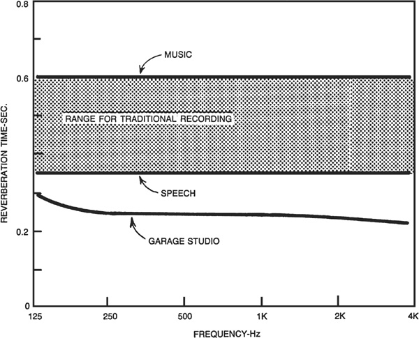
Reverberation time, of itself, does not play too important a role in multitrack recording because our primary goal is adequate track separation. Distinctive sound, not naturalness, is the goal of rock recording. Following through on the computations of Table 12.1, however, gives a good feel for comparing treatment of this type of studio with the more traditional speech and music studios. The drywall, carpet, and 4 inches of 703 areas are estimated. The extra bass absorption effect of the drum booth attic and the structure on the east wall are neglected as their effect over and above that of the 4 inches of 703 is largely below 125 Hz, the lowest frequency of Table 12.1.
TABLE 12.1 Studio Calculations
The calculated reverberation times of the studio range from 0.30 to 0.22 second as compared to 0.35–0.60 second if the same studio were treated for recording speech and traditional music (Fig. 12.6). This comparison emphasizes the general deadness of multitrack studios in the quest for track separation.
FIGURE 12.6 The reverberation time of the garage multitrack studio is far shorter than that for more traditional recording.
Studio deadness, of course, is not the only step toward adequate track separation. The use of baffles, microphone directivity, close placement of microphones, and other factors have their important effects.
Figuring the axial mode frequencies of a triangular room is far beyond the scope of this book, but the average ceiling height of about 9 feet would yield a fundamental of around 60 Hz; the others would not be too far from this. Cutting off the sharp corners near the window provides a shelf for the loudspeakers. To remove the bad effects of the cavity in which the loudspeakers sit, a heavy plywood baffle should be fitted around the face of the loudspeaker (Fig. 12.7).
FIGURE 12.7 Corner treatment in control room of garage multitrack studio. Helmholtz resonators having a peak of absorption in the low frequencies are built into the corners. These are slat type resonators.
The triangular space below the loudspeaker may be utilized as a low frequency absorber to help counteract the carpet effect. To coin a euphonious phrase, this is a slit resonator utilizing the slots between the slats and the cavity behind. It is made simply of 1 × 4s spaced about ¼ inch with 2 inches of 703 pressed against the rear of the slats. The cavity itself serves only to contain the springy air.
On the walls behind the operator about thirty 12 inch × 12 inch × ¾ inch acoustical tiles are cemented to each wall in a 6 × 5 array. This totals 60 square feet. Carpet covers the floor and the ceiling is drywall. The two resonators plus some 350 square feet of gypsum board compensate for the low frequency deficiencies of the tile and carpet, but not completely. This brings the reverberation time of the control room to about 0.34 second, rising to about 0.46 second below 250 Hz. With all the compromises involved there seems to be little justification for further acoustical adjustment.
No matter how high the average and peak levels of music are in the studio, there are those soft, sweet, and sentimental passages for contrast. The barking of a neighbor’s dog heard on the vocal track during such a passage is guaranteed to raise the emotional level even higher than the vocalist could hope for. Therefore, concrete walls 6 feet thick are longed for at such times, but they are just too expensive.
The simple walls of Fig. 12.3 are all this budget could stand. Statistics are on the side of the amateur or low budget recording job. How often do soft passages occur? How often do screaming motorcycles or other interfering noises occur? The permutations and combinations are such that redoing a very occasional ruined take is usually the answer for this type of studio. However, it is quite a different story if it costs $5,000 in studio time and for talent to redo the passage.
Very square neighbors have been known to identify that beautiful stuff being laid down in multitrack within the studio as noise. The difference in point of view can bring the police. In some communities the noise ordinance is as broad and general as this one:
It shall be unlawful for any person to make, cause or permit to be made, any loud or unusual noise which directly causes an unreasonable interference with the use, enjoyment and/or possession of any real property owned or occupied by any other person.
In an increasing number of communities a certain maximum allowable noise level is set for the boundary of the property on which the studio rests. In brief, the sounds escaping from the studio may give far more trouble than exterior sounds spoiling takes. Walls offer the same transmission loss both ways, and the walls of Fig. 12.3 certainly offer minimum transmission loss with respect to noise going either way.
Multitrack recording techniques require studios quite different from the traditional kind. Numerous books have been written on the multitrack subject13-15 as well as many articles in the technical press.16-26 I refer you to them for information on the host of pertinent points which cannot be covered in this book.