All the good things should be maximized, all the bad things minimized. This message is repeated frequently enough to encourage maximum recall with minimum effort. A new building was to be built, but many activities were in competition for the maximum space a minimum budget would allow.
As for recording studios, talk at first swung toward a large number of very small studios. This was parried by solid information on the adverse effect of small studio spaces on sound quality and it was agreed to reduce the number of studios so that at least the 1500 cubic foot minimum volume could be realized. Most of the work is the recording of voice programs, but numerous languages are involved, necessitating a multiplicity of studio-control room suites.
It is desirable to make all these suites very similar so that language teams can go from one to another with no delay or inconvenience caused by lack of familiarity. Essentially identical acoustics of all speech studios would also allow complete freedom in intercutting.
Music recording of fairly large vocal and instrumental groups requires one music recording studio, but this larger studio must also be capable of being pressed into service for voice recording at times. This is a very challenging and interesting set of requirements, the solution of which poses some technical problems of general interest.
Heretofore in this book splayed walls have been conspicuous by their scarcity. One reason for this is that many of the studios studied here were located in existing buildings. In such cases splaying of walls required either reconstruction of great sections of the building or losing precious studio volume, or both. This is costly financially and acoustically. Splayed walls do reduce the chance of flutter echoes being produced, even as well-distributed absorbing materials do. In a new building, however, splaying represents little or no additional cost and no loss of room volume. Under such conditions it is most logical to include it.
Figure 19.1 represents a typical speech studio-control room suite having:
FIGURE 19.1 Typical speech recording suite featuring rooms of about 1,500 cubic feet volume and splayed walls coordinated with a sound lock corridor. This is the basic unit of which the larger studio complex is composed.
• Rooms of minimum volume (about 1500 cubic feet)
• Two splayed walls in each room
• Sound lock space shared by two or more suites
• An equipment storage space for each two suites
This is certainly maximizing function in limited space as two speech studios, their associated control rooms, an adequate sound lock and a shared storeroom are obtained in a rectangular area about 17 feet × 24 feet with a ceiling height of 10 feet. The plan of the single recording suite of Fig. 19.1 thus becomes an elemental building block of the larger studio complex. This sets the pattern for all control rooms and all speech studios; in fact, everything but the music studio.
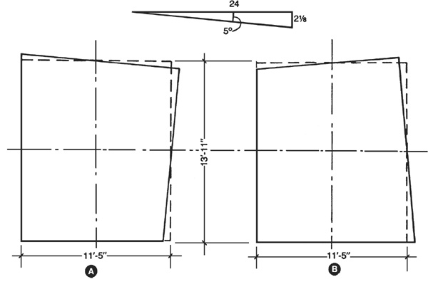
Normally walls are splayed 1:10 or 1:5. Ratios in this form are readily understood by construction workers but they can also be expressed in degrees (5.7 degrees or 11.3 degrees) by plugging 0.1 or 0.2 into the trusty calculator and punching arc-tan. Due to a trigonometric inclination and a love of round figures an even angle of 5 degrees was adopted for the splay of these studio walls which was later realized to be a very odd ratio for the construction people, 2 :24.
:24.
The scheme of splaying all speech studios and control rooms is illustrated graphically in Fig. 19.2. The two walls to be splayed are simply rotated 5 degrees about their midpoint. As two walls are involved, and each wall can be rotated clockwise or counterclockwise about its midpoint, there are four possible combinations of room shapes with the 90-degree corner held in the same position. This 90-degree corner can be placed in other positions by rotating or flopping the sketches. Three of these four possibilities account for all the room shapes to be included.
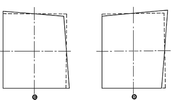
FIGURE 19.2 Splaying plan for the speech recording studios and associated control rooms. The two walls to be splayed in each room are rotated 5 degrees about their midpoints.
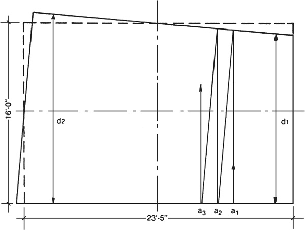
The larger music studio splaying plan is shown in Fig. 19.3. Actually, it is the plan of Fig. 19.2A adapted to the different proportions and dimensions of the music studio, Studio C. It should be emphasized at this point that the four splaying plans of Fig. 19.2 have somewhat different areas, even though based upon identical rectangles. It should also be remembered that only the N-S and E-W modes are touched with the above wall splays. The vertical flutter echo must be cared for in some other way.
FIGURE 19.3 Splaying plan for the larger music recording studio is also based on 5-degree rotation about the midpoint of each of the two walls.
To a first approximation the dimensions of the basic rectangle from which the splay pattern is derived can be used to establish proportions for the best distribution of axial modes. The actual modal frequencies, of course, differ slightly from these. One way of looking at it (Fig. 19.3) is that the sound energy reflected to a splayed wall from an opposing, but unsplayed, wall does not return to the same spot on the originating wall, a1, but returns to a2, a3, etc. It “walks the slope” and tends toward becoming a tangential mode.
Another approach is to consider dimension d1 to give one axial mode frequency and dimension d2 another one slightly lower. Both outlooks are based on geometrical acoustics which fail miserably in the low frequency region giving us the most trouble. It is really a very complex problem and the mathematical tool of wave acoustics is a more powerful approach. Although only an approximation, establishing favorable room proportions according to the basic presplaying rectangle is a logical and practical approach and the only simple alternative.
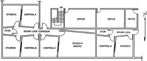
Using the typical speech studio-control room layout of Fig. 19.1 and the splaying plans of Figs. 19.2 and 19.3, the floor plan of Fig. 19.4 has been derived. It includes three speech studio suites, A, B, and D, and one music studio, Studio C, with its control room. Control Room C, serving the music studio, is comparable to the other smaller rooms. One sound lock corridor serves three studios and three control rooms. Were it not for the stairwell, all eight rooms might well have been served by a single sound lock. These studios are located in one corner of the top floor of the two-story building.
FIGURE 19.4 Floor plan incorporating three speech recording suites such as shown in Fig. 19.1 and a larger music recording studio. The control room for the music studio (Control Room C) is comparable to the speech studios and their control rooms.
As the building housing the studios is on a well-traveled boulevard in a major city, traffic noise must be considered. Traffic noise varies greatly with the time of day and the only way to evaluate it properly is to run at least a 24-hour noise survey on the proposed site. Obviously, there is less traffic at night and noise conditions are at their lowest point in the early morning hours, but the 24-hour survey makes possible such statements as “The noise level exceeds 75 dB(A) only 4 percent of the time.” This is the sort of data required to support various types of decisions.
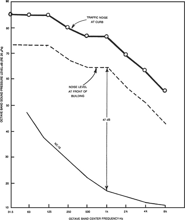
This ideal approach was not possible in this instance, therefore an octave analysis of peak boulevard traffic noise was made at the curb closest to the building site with the results shown in Fig. 19.5. This was done before the exact location of the building was known. Once the building location was set, the measured values at the curb were extrapolated to the nearest face of the building by assuming spherical divergence of sound with its resulting 6 dB reduction with each doubling of the distance from the line of traffic. This procedure yielded the broken line spectrum of Fig. 19.5, the estimated noise spectrum just outside the building.
FIGURE 19.5 Traffic noise peaks were measured at the boulevard curb and later (when the building position was established) extrapolated to the face of the building. The NC-15 contour is the goal for noise within the studio. The difference between these two graphs is the transmission loss the studio external walls must provide.
The NC-15 contour is our goal for noise level within studios and control rooms which, of course, could very well have noise contributions from other activity within the building, air-conditioning equipment, etc., in addition to traffic noise. At the moment, however, only traffic noise is under consideration.
Special urging resulted in the placement of the studio corner of the building on the side away from the boulevard. This offers some protection from traffic noise. The building code requires ventilation of the attic space above the studio area which means that traffic noise of considerable magnitude pervades the attic space immediately above the studio ceilings.
With the wall construction to be described later, the greatest prospect for a traffic noise problem in the studios turns out to be via this ceiling path. If sound level measurements within the studios reveal traffic noise levels appreciably above the NC-15 contour, a layer of sand will be added between the ceiling joists above the double dry-wall ceiling. A 1-inch layer of sand “beefs up” the ceiling, acoustically speaking, 36 dB at 500 Hz on a mass basis and weighs only about 8 pounds per square foot. Each doubling of the sand thickness adds 3 dB transmission loss, but doubles the weight.
It is advisable to stop short of a thickness at which sand would break through the ceiling and pour down on unsuspecting personnel below. A modest amount of sand could add very substantially to the insulation strength of the ceiling against external noise.
There is information in Fig. 19.5 which helps in deciding how heavy to make the external walls of the studio. The distance between the NC-15 contour and the broken line graph represents the minimum transmission loss the walls must provide. This loss requirement varies with frequency. It is maximum at about 1 kHz, decreasing for both lower and higher frequencies.
This is unfortunate in one sense because the sensitivity of human ears is greatest in this general frequency region.
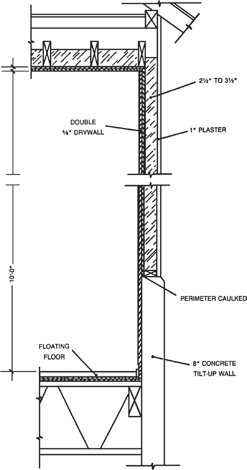
It is fortunate in another sense because walls of common materials and normal construction can offer quite good transmission loss at 1 kHz, much greater than at much lower frequencies. The octave noise level of 64 dB at the face of the building is 47 dB higher than the NC-15 contour at 1 kHz which we are striving for within the studio. The external wall construction of Fig. 19.6 was considered to be adequate to provide this much transmission loss, especially knowing that the 64 dB applies to the front face of the building and the external walls of the studios are in the rear. The lower part of the wall of Fig. 19.6 is the top of the tilt-up panels. The upper part of frame construction is plastered outside and covered with double  -inch gypsum drywall panels inside. The insulation between wall studs serves the double purpose of thermal insulation and discouraging acoustical resonances in the cavity which degrade the effectiveness of the wall in attenuating external noise.
FIGURE 19.6 Plan of external wall of studios and control rooms. Tight sealing of the base layer of gypsum board around its periphery contributes significantly to wall performance in protection of studios against external noise.
Ceiling construction is similar, except for the plaster. Should sand be added to the upper surface of the ceiling drywall at a later time, the insulation would first be removed, the sand applied and then the insulation would be replaced on top of the sand.
The construction of typical internal walls is specified in Fig. 19.7. Double layers of -inch gypsum board are standard on every wall or ceiling separating sound sensitive areas from outside noise. The gypsum panels of all studio walls (except external) are not nailed to the studs but are supported resiliently. The base layer board is secured to the resilient channels with screws. These resilient channels, U.S. Gypsum Rc-1 or equal, are first nailed horizontally to the studs, spaced 24 inches.
FIGURE 19.7 Plan of interior walls of studios and control rooms. On the studio side the base layer of gypsum board is screwed to resilient channels and the face layer is cemented to the base layer. Such a resilient mounting makes the resonance frequency of the wall diaphragm on the studio side different from that of nailed panels on the other side, preventing coincidence and thus improving transmission loss of the wall.
The vertical base layer board is then secured to the resilient channels with special screws of proper length so that the flexible action of the channel is not destroyed by screws hitting studs. The face layer of gypsum board is then applied horizontally with adhesive. All joints are then finished in the normal way.
Figure 19.8 illustrates the preferred method of staggering layers of gypsum board at corner intersections. The entire periphery of the base layer should be carefully caulked with nonhardening acoustical sealant. Such efforts toward hermetically sealing each room pays great dividends in reducing sound leaks and assuring maximum transmission loss of the wall. The resilient studio face of a wall resonates at a different frequency than the opposite nailed face.
FIGURE 19.8 Plan for staggering gypsum layers at corner joints to reduce noise leaks.
Such resonance effects tend to reduce transmission loss at the resonance frequency and different handling of the two wall faces displaces one resonance point from the other, improving overall wall performance.
To obtain sufficient protection against noise of other activities in ground floor rooms below the studio area, a floating concrete floor was required in studios and control rooms. There are numerous fancy mechanical ways of supporting floating floors on springs and rubber devices as well as proprietary impregnated glass fiberboards and strips which are excellent in floating floors, but expensive. An inexpensive method used in Germany a quarter of a century ago was pressed into service.32
A soft fiberboard is laid on the structural floor as a support for the concrete. The stiffness of the fiberboard is reduced by coating the underside of it with cork granules before laying it on the structural floor. The fiberboard is then covered with plastic sheets and overlapped at least 3 inches. It also runs up over the perimeter board indicated in Fig. 19.7. The concrete screed is thus prevented from running into cracks between fiber boards which would form solid bridges between the structural floor and the floating floor, destroying the floating characteristics. The cork granules improve the impact sound insulation about 16 dB over the fiberboard alone. The 1½-inch concrete thickness is certainly minimum.
To reinforce such a floor (wise precaution) the thickness of the concrete must be 3 inches to 4 inches. In thinner layers it is almost impossible to keep the reinforcing screen in the center of the concrete layer during the pouring. If the reinforcing wires are on the bottom of the layer, little reinforcing results. The danger is that concentrated loads, such as the legs of a grand piano, may crack the concrete, reducing its sound insulating value.
The specification of carpet for all studios dominates their acoustical treatment. The dry-wall wall and ceiling surfaces provide a modest, but insufficient, amount of low frequency compensation for the carpet. Helmholtz resonators can easily supply the remainder of compensation required, but the problem is, where to put them? Thick boxes on the walls and ceilings are not an esthetic delight. It was decided to use a frame suspended from the ceiling to hold the low frequency boxes and illumination fixtures and to shield both from view with a lower frame face of plastic louver panels of either egg crate or honeycomb type openings.
Should the usual panels of 4 inches of 703 Fiberglas adorn the walls? In the interests of appearance it was decided to employ proprietary panels of glass fiber covered with decorative, perforated vinyl wallcovering manufactured by L.E. Carpenter and Company (Appendix D). Vicracoustic panels 2 feet × 8 feet × 2 inches were selected. The core of semirigid glass fiber, which does the absorbing, can be covered on one or both sides with -inch high density glass fiber substrate if required for protection against impact.
In this studio application the less expensive Type 80 panel, which consists only of the absorbing core wrapped on face and edges with perforated vinyl, was considered adequate. Panels (Fig. 19.9) are mounted on the walls by the use of Z-clips, one part of which is cemented to the backs of the Vicracoustic panel, the other screwed to the wall.
FIGURE 19.9 The panels selected for use in all studios and control rooms are 2-foot × 8-foot Vicracoustic panels composed of 2 inches of dense glass fiber covered with an attractive perforated vinyl fabric. Mounting to walls is by use of Z-clips.
The low frequency absorption of these panels is increased from 0.47 to 0.57 at 125 Hz if the Z-clips are mounted on 1 × 3 strips, but the advantage of doing so at other frequencies is almost nil. The treatment of Studios A, B, C, and D is accomplished with carpet, low frequency Helmholtz resonators, and Vicracoustic panels added to the built-in absorption of the drywall surfaces.
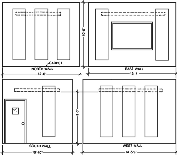
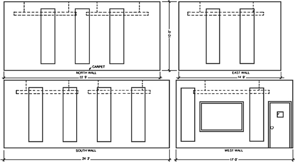
The placement of the Vicracoustic wall panels in Studio-A is shown in Fig. 19.10. Even though the east and south walls are splayed, an attempt is made to place panels on one wall to oppose bare wall (or window, or door) on the opposite wall. This can best be judged in the projected ceiling plan of Suite A in Fig. 19.11.
FIGURE 19.10 Wall elevations of Studio A showing placement of Vicracoustic panels. The broken lines indicate relative position of the suspended frame holding low peak absorbing boxes.
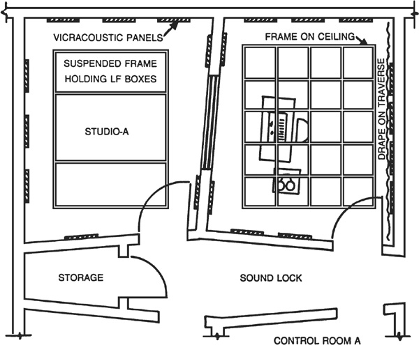
FIGURE 19.11 Projected ceiling plan of Studio A and its control room showing position of the following acoustical elements: Vicracoustic wall panels, frame suspended from ceiling in Studio A, frame fastened to ceiling in Control Room A and drapery on traverse in Control Room A.
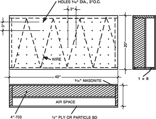
The constructional details of the low frequency absorbing boxes are given in Fig. 19.12. Similar to others considered in other chapters, the frame is of 1 × 8 lumber with a back of ½-inch plywood or particleboard. The face of 3/16-inch masonite is filled with 3/16-inch holes drilled on 3-inch centers. This gives a perforation percentage of about 0.3 percent and a resonance peak in the vicinity of 100 Hz.
FIGURE 19.12 Constructional details of Helmholtz type perforated face resonator which provides low frequency absorption to compensate for carpet deficiency in the studios.
The 4 inches of 703 glass fiber broadens this peak. The boxes should be spray painted with flat black paint to reduce their visibility.
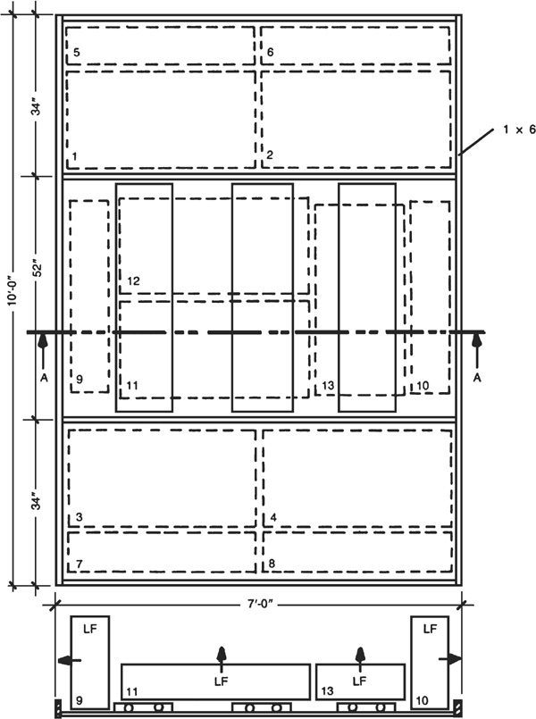
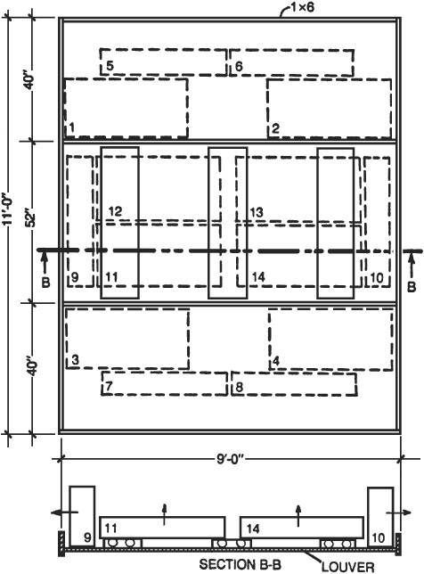
The 7 foot × 10 foot suspended frame is placed in Studio A approximately as indicated in the projected ceiling plan of Fig. 19.11. Figure 19.13 shows the relationship of the 1 × 6 frame and the plastic louver layer. The three fluorescent fixtures assure that the plastic louver plane is the dominant visual feature of the room.
FIGURE 19.13 Frame of 1 × 6 lumber suspended from the ceiling of Studio A which holds illumination fixtures and the 13 low frequency boxes required in the room. Some boxes face downward, some point upward, and others point in the four horizontal directions.
The 13 black low frequency boxes the frame contains will scarcely be visible. The placement of the low frequency boxes in the frame is important. Boxes 1, 2, 3, and 4 have their faces downward, resting on the open cells of the plastic louvers. Boxes 5 and 6 rest on their long edges and point north; 7 and 8 point south; 9 faces west; and 10 faces east. The three low frequency boxes 11, 12, and 13 resting on the fluorescent fixtures must, of course, be directed upward.
It is well that these last three have some soft material between the boxes and the metal reflectors to avoid sympathetic rattles when the room is filled with sound. In fact, an awareness of the possibility of rattles in the entire assembly is advised.
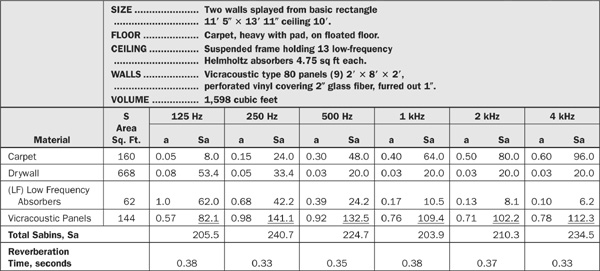
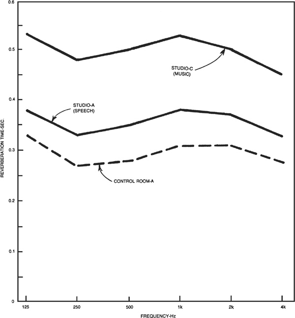
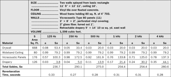
Table 19.1 lays out the details of calculating (estimating) the reverberation time of Studio A. A reverberation time of 0.35 second was the goal and the plotted graph for Studio A in Fig. 19.14 shows that this goal has been approximated. The exceptionally high absorption of the Vicracoustic panels at 250 Hz and 500 Hz generates the characteristic dip noticed in the control rooms and Studio C as well. An irregularity of this magnitude in the calculation stage has little significance unless confirmed by subsequent measurements. At that time, and not before, some trimming might be necessary and justified. The beauty of the modular acoustical treatment is that such trimming, if required, can be easily carried out.
TABLE 19.1 Speech Studio Calculations for Typical Studio A
FIGURE 19.14 Calculated reverberation time for Studio A as shown which compares to the goal of 0.35 second. The goal for Control Room A is 0.3 second and for Studio C, 0.5 second. Measurements must verify such calculated estimates. The modular treatment plan allows trimming if required.
The speech studios and control rooms are very similar in size and differ chiefly in the somewhat lower reverberation time goal of about 0.3 second for control rooms. Acoustically, a very major difference between the two types of rooms is that the floors of the control rooms are covered with vinyl tile instead of carpet. This factor means that the basic treatment will be accomplished primarily with wideband, or quasi-wideband, materials.
The grid of 1 × 6 lumber attached to control room ceilings makes 20 squares having inside dimensions of 24 inches × 24 inches which hold pads of 4 inches of 703 giving a total area of 80 square feet. The actual configuration is not too important, the effective area is.
Construction can follow similar frames described in earlier chapters with a fabric or screen facing. The air space between the 703 and the ceiling aids low frequency absorption of the material. The positioning of the ceiling frame is not critical, the position of Fig. 19.11 is suggested.
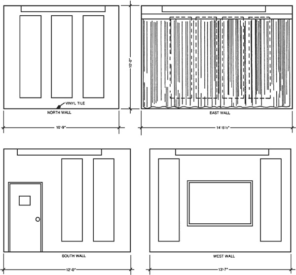
The placement of the Vicracoustic panels in typical Control Room A is shown in Fig. 19.15. The four panels on the east wall are normally hidden behind a drapery which is retractable. This drape is included to flatten the reverberation time at 1 kHz and above is very close to 0.3 second as shown in Table 19.2 and Fig. 19.14. If the drape is retracted the reverberation time in the same high frequency region is close to 0.35 second, making the 250 Hz dip stand out a bit more. This drape may be considered an approved variable acoustical element, if desired.
FIGURE 19.15 Wall elevations of Control Room A showing placement of Vicracoustic wall panels. The drape, normally covering the panels, is included to flatten the reverberation characteristic slightly. When retracted, the reverberation time in Control Room (A) is suitable for speech recording.
TABLE 19.2 Typical Control Room Calculations
With the drapes extended over the east wall, conditions are proper for listening to sounds from the speech studio with its reverberation time of 0.35 second. With the drapes retracted, the control room becomes more adaptable acoustically for recording an interview, for instance. The drapery material should not be too heavy (10 ounces per square yard material was used in the calculations).
Ordinary monk’s cloth, running about 8 ounces per square yard, is acceptable. It should be hung as close to the wall as possible and still clear the panels. Only enough material should be hung to result in the fold almost disappearing when the drapes are extended. Having deeply folded drapes would introduce too much absorption.
Music Studio C should have a longer reverberation time than the speech studios for two reasons, its greater volume and the fact that the music is better served by a longer reverberation time than used for speech. A goal of about 0.5 second was selected, compromising somewhat toward a speech requirement because the studio will be used for speech recording at times. In spite of its greater size, the music studio uses the same acoustical elements as the speech studios: carpet, Vicracoustic panels, and peaked low frequency absorbers.
Figure 19.16 shows the placement of the Vicracoustic panels on the walls of Music Studio C. The suspended ceiling frames are shown with broken lines, the lower edge being about 8 feet above the floor. These frames each hold 14 of the same low frequency resonator boxes used in the speech studios and described in Fig. 19.12.
FIGURE 19.16 Wall elevations of Studio C showing placement of Vicracoustic panels in this music recording studio. Two suspended frames are required for illumination and to hold low frequency boxes.
Figure 19.17 shows the configuration of the 14 low frequency boxes in one of the ceiling frames. In general, the plan is the same as for the speech studio frame: the perforated side of those standing on edge facing outward (5, 6, 7, 8, 9,10): those resting on the fluorescent fixtures (11,12,13,14) facing upward; and the rest (1, 2, 3, 4) facing downward.
FIGURE 19.17 Detail of one of the suspended frames in the music studio. The positions of the 14 low frequency boxes are indicated.
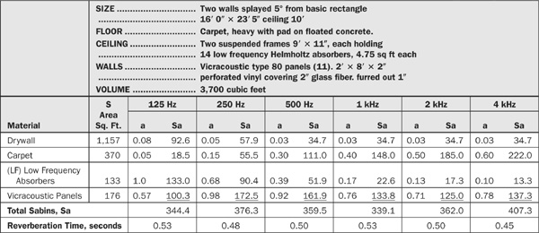
Table 19.3 reveals the details of the calculation of reverberation time for the music studio. The calculated values of reverberation time are plotted in Fig. 19.14. The deviations from the goal of 0.5 second are not significant, but measurements should verify the actual shape which will then be the basis of any trimming adjustments considered necessary.
TABLE 19.3 Calculations for the Music Studio C
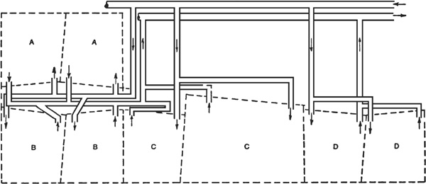
In Chapter 7 the several basic principles concerning air conditioning ducts in studios were elucidated. Applying these principles to the present case of multiple studio suites, the plan of Fig. 19.18 resulted. Note that the maximum length of duct is placed between grilles of adjacent rooms or even rooms on the opposite side of the sound lock. Supply and return grilles in a given room should not be too close together to assure adequate circulation. In the Control Room C return duct, a U-shaped section was inserted to avoid a short path to the adjoining room.
FIGURE 19.18 Air handling ducting plan for the studio complex. This plan places a maximum length of ducting between grilles of adjacent rooms to prevent crosstalk from room to room via the duct. Lined ducts attenuate sound in the ducts.