Most of what an artist needs to know about electronics is very simple. There may be a lot of little things to play with, but each component is easy to understand.
Start with the light-emitting diode, called an LED for short. You put electricity through it, and it lights up. That seems pretty simple.
Like all electronics, LEDs can seem a lot less simple if you don’t know their basic rules.
An LED has two wires coming out of it. If you connect one wire to the positive side of a battery, and the other side to the negative side of the battery, you have a 50 percent chance it will light up. If it doesn’t light up, turn the battery around and it will.
The first rule of LEDs is the diode part of the name at work: a diode only allows electricity to go through it in one direction.
The tiny little button-cell battery in the photo above is just strong enough to light the LED. What would happen if you connected the LED to the battery in a car, or to a 9-volt battery? That would not be a good idea. At best, the LED would make a little pop sound and become a dark-emitting diode, which we will call a DED.
The second rule of LEDs: they can only handle a certain amount of electricity.
Electricity is just moving electrons. As electrons move through a conductor such as a wire or an LED, they bump into the atoms in the conductor, causing the conductor to heat up. The temperature rises, but as the temperature becomes higher than that of the surroundings, more of the heat is lost to the environment. So eventually, the LED reaches a stable temperature, where the amount of heat generated equals the amount of heat lost.
Each second, some number of electrons move through the LED. If the number of electrons per second goes up, so does the temperature. At some point, the temperature of the LED is so high that the little chip inside the LED breaks or the tiny little wires that connect to the top of the LED chip simply melt.
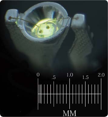
You can see two of those tiny little gold wires in the photo enlargement above. A yellow LED chip is glowing inside the small reflector cup. The entire LED is usually encased in a plastic lens, making it very difficult to see. But for this photo, I placed the glowing LED in some oil so that you could see through the plastic easily.
Just as a current of water is measured by how many gallons flow by each second, currents of electricity are measured by how many electrons flow by each second. Electrical current is measured in units called amperes.
The LED shown can handle about 0.030 amperes (30 milliamperes) before it overheats. Knowing that, you then need to make sure that no more than 30 milliamps go through the LED. You do that by adding a resistor.
A resistor is a bottleneck for electric current. A resistor can be something as simple as a narrow wire. The thinner the wire, the less electricity can go through it.
You can also make a resistor by using a wire made from something that electrons have a difficult time moving through. Carbon is such a material. It is made up of many little grains, and where the grains touch, the electrons can go from one grain to the next. However, the grains only touch in tiny spots, just like two balls can only touch in one tiny spot when put together. In this way, they restrict the flow of electrons like the thin wire does. Materials like carbon also hold on to their electrons more tightly than copper wire does, so there are fewer electrons available to move.
So you could try lighting an LED from a 9-volt battery through a resistor to keep the current below 30 milliamps. But how much resistance would you need?
A 9-volt battery pushes electrons through an LED three times harder than a 3-volt battery does. Voltage is just the pressure on the electrons. If you put more pressure on the electrons, more of them will flow through the resistor, and through the LED in each second.
To figure out how much resistance you need to add, you can measure the current in your circuit while you gradually reduce the resistance, until you get to the value you want.
I picked a few resistors almost at random to try in the circuit. Resistance is measured in ohms, and I picked two resistors with 220 ohms and one with 1,000 ohms. Resistors have color codes to tell you what values they are, and the two 220-ohm resistors have the color code red, red, brown, gold. You can memorize the resistor color codes or print them out on paper (see page 13 for more information), or you can just use a multimeter, which can measure the resistance directly.
Once you’ve chosen your resistors, you need a way to create the circuit connecting them, the battery, and the LED. The projects discussed in this book are going to use solderless breadboards a lot, since they make building such circuits much easier. A solderless breadboard has rows of holes you can poke wires into. On the edges are two rows of holes that are all electrically connected to the other holes in the same row. In the middle are numerous groups of holes in columns of five; each of the holes in a column is electrically connected to the other holes in the same column. If you put a wire into one of the five holes and a second wire into another of the same group of five, the two wires will be electrically connected.
In the photo above, my three resistors are connected to a battery, an LED, and a multimeter via a solderless breadboard. The resistors are the small brown tubes at the center of the breadboard (note the color-coded stripes). The electrons come out of the battery through the black wire. They then go through the LED. From there they go through one 220-ohm resistor, then the other, then the 1,000-ohm resistor, and then (via the yellow wire) into the multimeter. Finally, they exit the meter and return to the battery. They make the full circle through all the parts and back to the battery through the red wire. This is why it is called an electric circuit.
To help you understand how solderless breadboards are constructed, the photo below shows one where I have removed the sticky tape from the back so that you can see the rows and columns of metal connectors joining all the holes. Each connector is a U-shaped bit of metal that is springy enough to open up a little when a wire is pushed into it but strong enough to hold the wire in place.

Now back to the original circuit. The meter is showing that there are only 5.2 milliamps flowing through the LED and the resistors. Since you wanted 30 milliamps, you know that you have too much resistance.

Try using just the 1,000-ohm resistor. The photo on the previous page shows the meter reads 7.6 milliamps. That is a little closer but still not the 30 milliamps you want. You want the LED to glow as brightly as it safely can.

The photo above shows the circuit with just the two 220-ohm resistors (440 ohms altogether). The meter is showing 16.5 milliamps, more than half of what you are aiming for. What happens if you use just one of the 220-ohm resistors?
Oops! You overshot the mark … but not by a lot. You are only high by a little less than 7 percent, and the LED can handle that. No popping noises, no dark-emitting diodes. Success!
Rather than do all of that resistor swapping and guessing, wouldn’t it be nice if you could just plug in the voltage you have, and the current you want, and have a calculator figure out what resistor to use? You can, but to figure out what to enter into the calculator, you need to know a third rule about diodes.
In the photo above, the meter leads are connected to the leads of the LED in the circuit. The multimeter has been switched to read volts. The meter tells you that the voltage difference between those two spots (the two legs of the diode) is 1.754 volts. Each different kind of diode has a characteristic voltage, called the forward voltage drop. For red LEDs, it is about 1.75 to 1.8 volts. For other colors, it is higher as the colors go through the spectrum. Green LEDs might be 2.3 volts. Blue LEDs are around 3 volts. The voltage drop can be measured, as you just did, or you can just read it on the back of the LED package.
Now you have enough information to use a calculator.
The resistance you need is the voltage divided by the current. This is called Ohm’s law, named after scientist Georg Ohm, who worked it out.
The voltage is the voltage of the battery minus the voltage drop of the diode. In this case, the battery voltage is 8.46 volts (you can measure it in your circuit, as I did in the photo above). Subtract 1.754 volts and get a little over 6.7 volts. If you divide that by 0.030 amperes (the current the LED can handle without overheating), you get about 224 ohms.
If you have a computer or a smartphone, Google can help you do the calculation. Google knows that volts divided by amps gives you ohms. Try typing the following into Google:
(8.46 volts - 1.754 volts) / 30 milliamps
In this circuit, you found that you got 32 milliamps from your 220-ohm resistor. You can ask Google to give you the voltage:
Google says the result is 7.04 volts. But you expected 6.7 volts! What went wrong?
Let’s check the resistance by connecting the resistor directly to the meter:

It turns out the resistor wasn’t actually 220 ohms. It was 215.2 ohms. Ask Google again:
32 milliamps * 215.2 ohms
Oh, good! Now you get 6.8864 volts, which is very close to the 6.7 volts you expected.
The gold band on the resistor tells you that the resistor has a tolerance of 5 percent, which means its actual value will be within 5 percent of the value coded in the color codes. In this case, it is 2.2 percent off. You can expect a certain amount of sloppiness in your measurements—meters are not perfect, and the connections you make are not perfect—and in your parts values, such as in the case of this resistor. And you saw that your LED could handle 32 milliamps instead of the 30 the package recommended to limit the current to. When your parts are specified to only 5 percent accuracy, you can tolerate that much slop in your results.
10 volts / 50 milliamperes is 200 ohms.
2 amperes * 300 ohms is 600 volts.
120 volts / 2000 ohms in milliamperes is 60 milliamperes.
Memorize the following three relations, which will allow you to calculate any of the three measurements as long as you know the other two:
resistance = volts ÷ current
voltage = current × resistance
current = volts ÷ resistance
Or, if you memorize just one equation, a little algebra will allow you to rearrange the terms and arrive at the other two. On the other hand, you can just tell Google to multiply or divide the two measurements you have, and if the answer isn’t in the units you’re missing (volts, ohms, or amperes), you change the multiply to a divide, or vice-versa. In other words, even if you hate algebra and hate memorizing, you can still work it out.
Resistors are rather small things. Not only would it be difficult to print the resistance value on them, but also that value would be difficult to read. On a crowded circuit board, you might also have to turn your head different ways to read different resistors, and the printing might not be on the side facing you.
To get around these difficulties, manufacturers use the aforementioned color code. It’s not that hard to learn, but if you don’t use it every day, you might find yourself learning it over and over again.
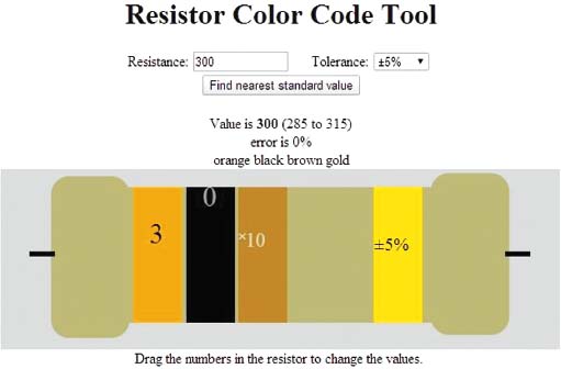
The website that accompanies this book has a page (http://artists.sci-toys.com/calculate_resistance.php) with an interactive tool that allows you to find the resistance you need and to quickly use color codes in a painless manner:
The first two bands indicate a numerical value—30 in the example above. The third band is a multiplier—you multiply the number from the first two bands by this amount to arrive at the value of the resistor. In this case, the multiplier is 10, so the value is 30 × 10, or 300 ohms.
The last band is the tolerance—as mentioned earlier, the allowable difference between the resistor’s coded value and its actual value. The most common resistors have a tolerance of plus or minus 5 percent. As a result, resistors are not made in all possible values; there is no reason to make a 105-ohm resistor if you are already making 100-ohm and 110-ohm resistors. You can buy more expensive resistors that have closer tolerances, but for the most part the 5 percent resistors will be all you really need.
The color coding makes it easier to find the resistors you need in a pile on the table. You look first for the multiplier band, and that gets you to the approximate value you need. Then you look at the first few bands to narrow the search to the exact value you need. In many cases, you will be experimenting and the exact value may not matter at first; you can just look at the multiplier band and test a resistor with the appropriate multiplier in your circuit. Once you test that resistor, you can look at the first two bands and find one with the same multiplier but a slightly larger or smaller value.
Rather than write lots of zeros for the larger values, resistors are described in terms of kiloohms (or k-ohms) and megohms, for multiples of 1,000 (kilo) and 1 million (mega).
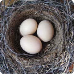
Adding LED lighting to small art pieces can transform them. A nest of hollowed-out chicken eggs can make one statement by day …
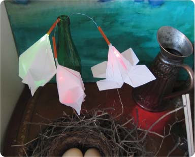
… and look entirely different at night.

If you want to make your own glowing nest, carefully make a hole in the side of an egg (not one of the ends) a little larger than the LED you will be inserting. About an inch from that, make a smaller hole to allow air to come in as you suck the contents out of the egg. A little washing, and you can insert an LED inside—a high-brightness white LED in this case. Add a current-limiting resistor and a battery and you are all done. I used sandpaper to rough up the clear surface of the LEDs to make them diffused, since most super-high-brightness LEDs are water clear.
This first project, however, is Electric Flowers. You will hide bright, colored LEDs inside origami flowers and arrange them in a vase made from a recycled bottle.
First, select a power supply. You don’t want to be constantly changing batteries, so use a 9-volt plug-in power supply from an old toy. These are often referred to as “wall warts,” since the transformer and other electronics that reduce the wall socket power down to (in this case) 9 volts are hidden in a plastic shell that plugs into the wall. Make sure you’re using a 9-volt wall wart; you should of course never use a plain cord plugged into the wall, which carries 100 or 200 volts of AC power.
The LEDs shown in this project have a forward voltage drop of 3.6 volts. So the voltage needed for the current calculations is: 9 volts - 3.6 volts = 5.4 volts.
These LEDs are rather robust and can handle 200 milliamperes of current, glowing quite brightly when they do. They will eventually die after a few hours, but for a short time, they can handle the high current. If you want a more lasting bouquet, use more resistance—limit the current to 30 milliamps per LED—and simply use more LEDs if you want more light. I used the high current to make them more visible in the photographs.
Divide 5.4 volts by 200 milliamps to get 27 ohms; that is what you select as your current-limiting resistor.

Solder the resistor to one lead of the LED (either lead will do, it doesn’t matter which). Solder a couple of wire leads to the LED and the resistor to act as the stem of your flower. I used the green pair from a short length of CAT5 network wire, because I happen to have lots of that around. Any insulated wire will do, but it should look nice.
Earlier I made some origami flowers out of plain white paper. There are many sets of instructions online for making hundreds of different types of origami flowers, so I won’t repeat those instructions here. But select a deep flower type that can hide the LED easily.
Cut the bottom of the flower off so that there is a small hole just big enough for the wires, but not the LED, to fit through. Push the wires through, and pull until the LED fits snugly inside the flower. Use some transparent tape to hold it in place. Then cut about a 1½-inch length of plastic straw to pull up over the wire ends to hide the connection.


In the photo above you can see a blue flower from a couple different angles, and in the dark. It is powered by a 9-volt battery for testing.
To complete the project, drill a hole in the bottle near the bottom, so the wires from the wall wart power supply can be threaded through (remove any connector from the end of the wire). Then solder all of the positive flower wires to the positive side of the power supply and all the negative wires to the negative side, making sure they all light up and no wires are swapped. Insulate the soldered connections with a little electrical tape and pull the wires down into the bottle to hide them. The flowers droop over the bottle to illuminate the table under them, like little nightlights. You can see the pool of red light under the flower on the right in the following photo even in the daytime. The other flowers are bell shaped and hide more of their light inside.
At night, the flowers glow.

STUDENT ART PROJECT
Collateral Damage by Bethany Carlson Mann is an example of how simple LED circuits can add depth and life to a piece.