For many electronic appliances and art pieces, turning the device on or off simply means plugging it in or unplugging it from the wall. Other devices have simple switches, which are not a lot more complicated than plugging into a wall. A switch simply connects two wires together electrically. You can do this by hand for low-voltage things like LEDs. Just touch two wires together and it lights up. You have made a simple switch.
You also know that the brightness of the LED is determined by how much current is flowing through it. And you know you can limit the current using a resistor. This means you know how to dim the lights: just increase the resistance.
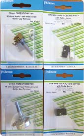
You can also replace your current-limiting resistor with a variable resistor. The technical name for a variable resistor is a potentiometer. Volume controls on radios and televisions were once simple potentiometers. These days they are more often buttons on a remote control that tell a computer how much to amplify the sound.
Since potentiometers can be set to 0 (no resistance), you will still want to have a fixed resistor to ensure that you don’t burn out the LED with too much current. The potentiometer can then be selected to have, for example, 2,000 or 5,000 ohms of resistance when it is at its highest setting (equivalent to the lowest volume on a volume control). The LED will appear to be so dim that it looks like it is off, until you turn up the current by rotating the knob on the potentiometer.
Because the word potentiometer has too many syllables, it is often referred to simply as a pot (like the one calling the kettle black).
A potentiometer has three terminals you can solder wires to. The outside terminals are connected to each end of a resistor, just like the ones you used in the LED project. The center terminal connects to a wiper. The wiper is a piece of metal that moves from one end of the resistor to the other, making a connection to the resistor material. The schematic symbol for the potentiometer shows the wiper as an arrow pointing to the middle of the resistor.

If you ignore the wiper and simply connect the outside terminals of the pot in the circuit, you just have an expensive resistor. But if you connect the wiper and one of the outside terminals, you have a variable resistor, also known as a rheostat. When you connect the outside terminals to the two ends of a battery, you have a voltage divider. (Remember the voltage divider discussed earlier?) The wiper then lets you select any voltage, from the highest the battery can deliver to 0, with a convenient twist of the knob.
Sometimes you want something to turn on and off by itself, without someone’s hand being involved. You see blinking lights on all kinds of things—they draw your attention, as is their purpose. To make a light blink, you need something that changes over time. That something is an electronic part called a capacitor.
A capacitor is a very simple thing. It is two conducting surfaces separated by an insulator. When connected to a voltage source, such as a battery, one surface in the capacitor gets electrons pushed onto it and the other surface gets electrons removed from it. This results in storing electrical energy in the capacitor, very much like charging a battery. That is because when you put an LED in place of the battery, the electrons crowded onto one surface race through the LED to the surface that is deficient in electrons. This lights the LED, until the surfaces are balanced again.
It takes time to charge a capacitor, and it takes time to discharge one. You can change this timing by limiting how fast the electrons can get into and out of the capacitor. You do this with a current-limiting resistor.
The combination of a capacitor and a resistor creates a way of telling time. If you allow the capacitor to charge through the resistor, the voltage between the two surfaces in the capacitor rises until it gets close to the voltage of the battery. It continues to gradually get closer and closer to the battery voltage, but the rate of voltage rise gets slower and slower, exponentially.
In the diagram on the next page, the box on the right is an oscilloscope, a device that shows voltages changing over time. It is connected at either end of the capacitor—represented by the new schematic symbol just below the resistor. A battery—the new schematic symbol on the left—provides (in this case) 3 volts. A switch—the new schematic symbol at the top—can connect the resistor and capacitor to either the top of the battery, giving it power, or the bottom of the battery, shorting it out.
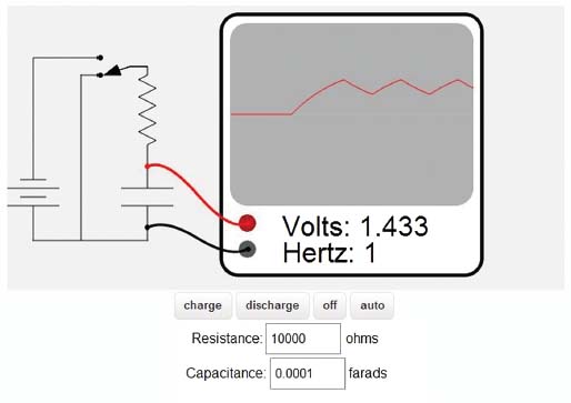
On my website (http://artists.sci-toys.com/flashing), you can click on the Charge and Discharge buttons to watch the capacitor charge or discharge. You can also change the values of the resistor and capacitor.
You can set up a circuit made of transistors that charges a capacitor through a resistor and monitors the voltage level. When the voltage rises to a particular level, the circuit will switch to discharging the capacitor through a resistor until the voltage reaches a second, lower level. At this point, it starts charging again, and the cycle repeats. You now have a circuit that can tick at any rate you desire, simply by making the capacitor bigger or smaller, or making the resistor bigger or smaller, or some combination. This circuit is called a timer. In the diagram on the website, clicking on the Auto button simulates a timer.
Timers are so useful in electronics that companies make integrated circuit chips that include all of the transistors and other components, all connected for you already, in a little chip. All that remains is to add the capacitor and two resistors, one to charge through and one to discharge through. This lets you set the timing however you desire.
The simplest timer you can create uses just a capacitor, a resistor, an LED, and a switch. In this project, you will build the second-simplest timer, by adding another resistor.
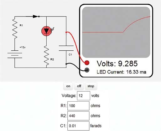
In the schematic shown above (http://artists.sci-toys.com/slowswitch) you can see that there is a resistor near the battery labeled R1. That is the charging resistor, and it determines how fast the capacitor will charge. In the middle you can see the LED and its current-limiting resistor.
When you push the On button, the switch closes and the capacitor begins to charge. The voltage across the LED and its current-limiting resistor is at first not high enough to turn the LED on. The LED is acting as a second (open) switch, keeping any of the current from going through it or its resistor.
At some point, however, the voltage gets high enough (in this case about 1.7 volts) that the LED turns on and current starts to flow through it and through its resistor.
Now the capacitor starts to charge more slowly, since some of the current is being diverted to the LED.
As the voltage on the capacitor rises, the current through the LED increases and it gets brighter. In this simulation, when the LED current exceeds 20 milliamperes, the LED turns yellow, as a warning that the current is higher than the LED is rated for. If the current ever exceeds twice the rated current, the diode turns brown, stops emitting light, and stops allowing current to flow through it. It is now a DED.
After the capacitor has charged for a while, click on the Off button. The battery and its resistor are now disconnected, and the capacitor discharges through the LED and its current-limiting resistor. The size of that resistor not only protects the LED from getting too much current but also determines how long it takes the capacitor to discharge.
What you have built is a slow switch. When you turn it on, the LED slowly gets brighter. When you turn it off, the LED slowly gets dimmer.
Notice that once the LED has stopped glowing, very little current goes through it and the capacitor seems almost to stop discharging. Diodes have a very small conductance (a very high resistance) when the voltage is below their “on” threshold, so the capacitor can only drain very slowly through the unlit LED. Capacitors also have some internal resistance, although it is also very high. It will take a long time for the capacitor to completely drain to zero.
You can play with the values of the resistors and the size of the capacitor to set the timing to your liking. Because the current-limiting resistor for the LED serves two purposes—limiting the LED current and determining the time it takes the LED to fade—you will find that it is simplest to select a value for it first, with the idea of protecting the LED, and then select the size of the capacitor (the other factor that determines the speed at which the LED fades) to set the fade time. When you are happy with the fade time, select the charging resistor to set the charging time.
You can thus have complete control over how long it takes to light the LED fully and how long it takes for it to fade completely.
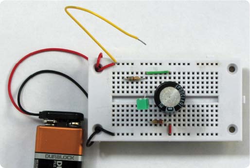
The photo above shows the circuit built on a solderless breadboard. I used a simple homemade switch, just a bit of yellow wire that was plugged into the breadboard to complete the circuit.
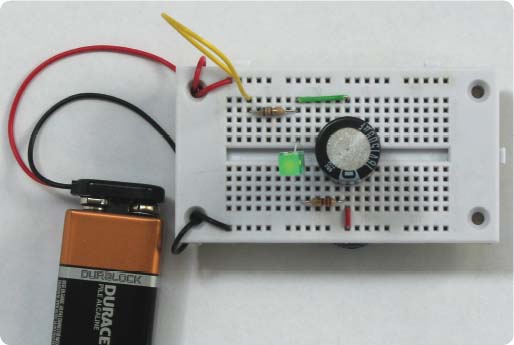
At the bottom of the previous page, you can see the circuit in the “on” state, and below is a diagram showing how the electrons flow through the circuit. Remember, on a board like this the holes in the top and bottom rows are electrically connected to all the other holes in their rows, while each hole in one of the middle columns is electrically connected to the other four holes in its column.
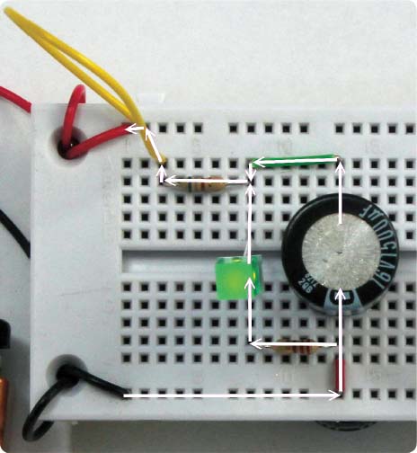
The big round thing on the right is an aluminum electrolytic capacitor. You see it here only in the top view, but it is a cylinder about an inch tall.
The LED is easy to spot by the difference between the “off” and “on” photos. It is the green square object.
You now know how to control electrical current with resistors and how to store electrical charge in capacitors. You know how to combine those two parts to create a time delay. You are now ready to use that knowledge in your first project that uses an integrated circuit chip.
The 555 timer chip is a tiny little thing that has several transistors and resistors all connected together inside to make a building block for electronics projects that works like an electrical Lego block. You will combine it with some resistors, a capacitor, and an LED to make the LED turn on and off at any rate you choose.
The 555 is a versatile building block, and it is so handy that over a billion of them are manufactured and sold every year. What it does in this project is fairly simple: it charges an external capacitor through an external resistor until the capacitor reaches two-thirds of the power-supply voltage. Then it flips an internal switch and starts discharging the capacitor through another external resistor until the capacitor reaches one-third of the power-supply voltage. Then the switch flips again and the process repeats, over and over again. This action makes the circuit an oscillator.
The little chip can also be configured to be a timer. In that configuration it simply turns something on or off for a specific time and then returns to its previous state.
Later you will use the chip to change the brightness of an LED and to control motors. But for now, you are going to control how your LED flashes on and off.

STUDENT ART PROJECT
In Our House, Patrick Stafford controls the brightness of red, green, and blue LEDs to bring a molded glass sculpture to life in millions of colors as the light mixes and each LED dims and brightens.
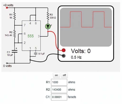
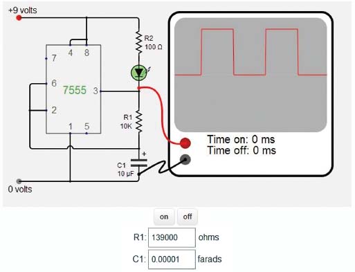
Look for a moment at just the left-hand side of the schematic shown above (http://artists.sci-toys.com/555). Between the positive and negative sides of the power supply, there are two resistors and a capacitor. If the 555 timer chip is not there, the capacitor will charge through the two resistors until it approaches 9 volts.
You know from the earlier discussion of capacitors that this takes some time. That is the key to how this circuit works.
How It Works
When you first connect the power supply, the LED turns on. This is because pin 3 of the 555 timer starts out at 0 volts—it is connected to the negative side of the power supply by an internal switch. This allows current to flow through the LED and its current-limiting resistor, R3.
As the capacitor charges, the voltage at pin 2 gradually rises.
Pin 2 of the 555 timer is called the trigger pin. If the voltage at this pin reaches 6 volts (two-thirds of the power-supply voltage), the chip will use some internal switches to connect pin 3 to the positive power supply (so you see 9 volts on pin 3) and connect pin 7 to the negative power supply, so you see 0 volts on pin 7.
When pin 3 is at 9 volts, the LED turns off, because both sides of the LED have the same voltage and no current flows through anything if both sides are at the same voltage.
Pin 7 of the 555 timer is called the discharge pin. When it goes to 0 volts, all the power goes through resistor R1 and almost none of it gets to any of the rest of the circuit. The capacitor not only stops charging but starts discharging through R2 into pin 7. The voltage at pin 2 starts to slowly drop from 6 volts down to 3 volts.
Pin 6 of the 555 timer is called the threshold pin. In this circuit you have connected it to the same place as pin 2, so it also monitors the voltage on the capacitor.
When the voltage at pin 6 reaches 3 volts (one-third of the power-supply voltage), the internal switches are reset. Pin 7 is no longer connected to the negative power supply, and pin 3 is. The LED turns back on, and the capacitor starts charging again.
So the whole circuit now oscillates, going from one state to the other and back again. The voltage at the capacitor goes from 6 volts to 3 volts and back again, and the LED turns on, then off, and then back on, over and over.
You may want to take some time to study the preceding description until it makes complete sense to you before we start talking about the rest of the pins on the 555 timer.
The Other Pins
Pin 1 is connected to the negative side of the power supply. This side is called ground in electronics, and in many circuits (like the power to your house), it is actually connected to a big metal spike driven into the dirt on which the house is built. This is why it is called ground. The Earth is so big that it can absorb as many electrons as we can give it, and you can’t detect any change in its voltage. It can also deliver as many electrons as a circuit can suck out of it, and still never seem to change voltage. If your house wiring were not electrically connected to the ground, you might get a shock when you touched a lamp or appliance, as the house current would use your body as a conductor to send current into the Earth.
The circuit in this project is probably battery operated, so it doesn’t actually need to be connected to the Earth, but the negative side of the battery is still called ground, and that term will be used a lot in the remainder of this book.
Pin 8 of the 555 timer is connected to the positive side of the power supply. This is how the chip gets the power it needs to operate.
Pins 4 and 5 are used to change how the chip operates. In your circuit, pin 4 (the reset pin) is not used, and you connect it to the positive power supply to ensure that it does not change and suddenly reset the timer. Pin 5 is the control pin and is also not used in the circuit. You connect it to ground through a small capacitor to ensure that it also stays stable. The small capacitor absorbs any sudden changes in the power supply (these sudden changes are called noise) that might result from other circuits turning on and off. Since there are no other circuits in this simple example, you could actually eliminate the capacitor and leave pin 5 unconnected. But it is a good practice to connect it, just in case.
Changing the Circuit
Now look at what happens if you change the values of the resistors or the capacitor. If you make the capacitor bigger, it will take longer for it to charge and discharge. The rate at which the LED blinks on and off will get slower. If you make the capacitor smaller, the LED flashes on and off more quickly.
The capacitor charges through both resistors, but it discharges only through R2. This means the LED will always be on longer than it will be off. If you make R2 very large, and R1 very small, this difference will decrease until it is barely noticeable.
But you can’t decrease R1 too much or the circuit won’t work. Remember that when the capacitor reaches 6 volts, pin 7 goes to 0 and the battery drains directly through R1. If R1 is too small, it will overheat and the battery will not last very long. If the resistance of R1 was 0 (as if it was replaced with a plain wire), all the current from the battery would flow directly from one terminal to the other, in what is called a short circuit (the current takes a shorter path than it would if it went through the whole circuit). If that happens, the chip will not get any current and it will stop working. For that reason, don’t use less than 1,000 ohms for R1.
If you keep R1 as low as possible, so that the “on” and “off” times are as equal as possible, then the timing is controlled mainly by R2 and the capacitor. Making R2 large means that the capacitor charges and discharges slowly. You can use a large R2 and a small capacitor, or a small R2 and a large capacitor, and get the same timing.
A New Chip: The 7555
Since the original 555 came out, low-power versions have come out. The low-power version—the 7555—is better for use in battery-powered devices, since it uses less power. The chip itself not only uses less power, but because its trigger and threshold pins are more sensitive, you can use higher value resistors, so less battery current is wasted. Higher resistances allow you to use a smaller (cheaper) capacitor. The 7555 can also reach higher and lower frequencies. In the 7555, the reset pin usually does not need a capacitor, making the circuit simpler and cheaper.
The potential drawbacks to the 7555 are that it is sensitive to static electricity until it is wired into a circuit, so you have to be careful to discharge your hands before handling it: just touch a large metal object to remove any static electricity from your fingers. The original 555 chip can supply more current (up to 200 milliamperes) to the LED than the 7555 can.
The amount of current the 7555 can provide depends on the power-supply voltage, and on whether the LED (or some other load) is connected to the positive side of the power supply or is connected to ground. If the chip is delivering current through the LED to ground, it is said to be “sourcing” the current. If the LED is connected to the positive side of the power supply, and the current goes through the 7555 to ground, the chip is said to be “sinking” the current.
The 7555 can source only about 2 milliamperes at 5 volts, but it can sink 8 milliamps. At 12 volts things are a little better—it can source 10 milliamps and sink 50. At 15 volts, it can source and sink 100 milliamps.
While this limited current capability might be a problem if you were driving a lot of LEDs, or trying to run a motor, for blinking a single LED, you can use it to your advantage and eliminate the current-limiting resistor for the LED. If the chip can’t deliver more than 20 milliamps to the LED, then the resistor is not needed.
Because both the 555 and the 7555 can source current as well as sink current, you can alternately drive two LEDs, each one off while the other is on.
In the circuit on the next page (http://artists.sci-toys.com/changing) you have eliminated the capacitor on pin 5, leaving it unconnected, since the 7555 version of the chip does not need it for this circuit. You also now have two LEDs connected to pin 3 of the chip. One goes to ground, through a 10,000-ohm resistor, and the other goes to the positive power supply through another 10,000-ohm resistor.
Note that you have two LEDs and two resistors making a direct link between power and ground. Without the 7555 chip and the rest of the circuitry, these LEDs would both simply light up. With the 7555 in the circuit, pin 3 alternates between +9 volts and ground. This makes one or the other LED turn off. You need the high resistor values because the chip can’t source or sink very much current, so the current going through the LEDs without the chip in the circuit must be less than the current the chip can source or sink. If you didn’t have high value resistors, one or both LEDs would simply stay on.
You may have noticed that the LED takes a while to turn on at first. When the capacitor is completely discharged, as it is when you first apply power, the voltage has to climb all the way from 0 to 6 volts before the top LED turns off. After that, however, it never gets down to 0 volts, since it starts charging again when it gets down to 3 volts. So the first time the LED lights, it stays on longer than on subsequent oscillations.
If you want to keep the “on” and “off” times the same, the 7555 allows you to simplify the circuit (http://artists.sci-toys.com/changing):
Instead of using the discharge pin (pin 7), you use the output pin (pin 3) to discharge the capacitor. The 7555 can pull pin 3 quite close to 0 volts, acting much like pin 7. So you can leave pin 7 unconnected. You could almost eliminate the current-limiting resistor for the LED, since it will not get enough current to be damaged (the 7555 can’t sink as much current as the original 555). But the 7555 isn’t strong enough to pull pin 3 down to ground unless there is some resistance between the LED and the positive power supply, so you still need a small resistor.
The result is a simpler circuit, where the frequency of the oscillation is controlled by a single resistor and a single capacitor. And because the capacitor drains through the same resistor that it charges from, the “on” time is the same as the “off” time.
One last note. The schematic shows a connection from pin 2 to the capacitor crossing over the connection between pin 1 and ground. The little bump in the line shows that these two wires are not electrically connected.
If you want the math …
The frequency of this last circuit is:
Since the natural log of 2 is a constant (approximately 0.6931471806), and twice that is also a constant (1.386294361), and the values for the resistor and capacitor are only good to a few percent (so you don’t need all that much precision in your constant), you can simplify this to:

For the first circuit, with two resistors, the frequency is

The “on” time will be 0.7 (R1 + R2) C.
The “off” time will be 0.7 R2 C.
You explored earlier how to dim an LED using a resistor.
When you put a resistor in series with an LED, the same current flows in the resistor as in the LED. The current that flows in the LED is useful—it goes mostly into providing the light you want. The current that flows in the resistor creates heat. This is a waste of energy if all you want from the circuit is light.
The amount of power lost (dissipated) in the resistor is something you can calculate. The power (in watts) is the current squared, divided by the resistance. Using Ohm’s law, you can restate this in the following ways:
Watts = amperes2 × ohms
Watts = volts × amperes
Watts = volts2 ÷ ohms
In the simple circuit (page 13) where 6.8864 volts causes 32 milliamperes to flow in both the LED and the 215.2-ohm resistor, you lose:
(0.032 amperes × 0.032 amperes) × 215.2 ohms = 0.2203648 watts
0.032 amperes × 6.8864 volts = 0.2203648 watts
6.8864 volts × 6.8864 volts ÷ 215.2 ohms = 0.2203648 watts
You are losing almost a quarter of a watt in the resistor.
What That Means
Suppose you are powering this earlier simple circuit with a 9-volt battery. The battery can supply 0.565 ampere-hours at 9 volts, for a total energy capacity of 5.085 watt-hours of energy.
Your circuit draws 32 milliamperes of current, so you would expect the battery to last 17.6562 hours. During those 17 hours, the resistor is dissipating just under a quarter watt of power in the form of heat for each of those 17 hours. That’s 17.6562 hours × 0.2203648 watts, or 3.89 watt-hours of power. That’s more than three-quarters of the power in the battery, all wasted as heat in the resistor.
A More Efficient Circuit
Suppose you replace the resistor with some more LEDs. Each LED drops the voltage by 1.754 volts (see the earlier discussion of this circuit, page 10), so five LEDs in series would drop 8.77 volts.
I built the circuit, and here’s what I measured. The battery was putting out 9.38 volts. With five LEDs in series, the current was 1.71 milliamperes. The five LEDs were dim.
With four LEDs in series, the voltage dropped to 9.27 volts and the current jumped to 24.7 milliamperes. The LEDs were nicely bright.
Since the amount of light is proportional to the current, you can calculate how much light each circuit produces relative to the other. The LED and resistor had a current of 32 milliamperes. The five LEDs in series had 1.71 × 5, or 8.55 milliamperes producing light. The four LEDs in series had 24.7 × 4, or 98.8 milliamperes producing current. So the four LEDs are producing 3.0875 times as much light as the single LED with its current-limiting resistor while using only 77 percent as much current (24.7 ÷ 32).
The new circuit can run 22.8744 hours on the same battery and put out three times as much light.
Dimming Using the 555 Chip
With your first circuit, you could dim the LED simply by making the resistor a little bigger. But now you have three times as much light and no resistor to change to control how much light is emitted.
You can steal an idea from movies and television to dim the LED without wasting power as heat. Movies and television flash many frames per second to our eyes, but the flashes are coming so fast that our eyes and brains perceive them as a steady light.
You can use the 555 chip to flash the LEDs so fast that your eyes see them as staying on all the time. But half the time they are off, so they appear half as bright.
The 555 lets you control how long the LEDs are on and how long they are off. So you can vary the brightness from 0 to 100 percent by changing how long they are on in each brief flash. This method of controlling the brightness is called pulse width modulation (PWM). You are modulating (changing) the width of the pulses to control how much total energy is converted into light by the LEDs.
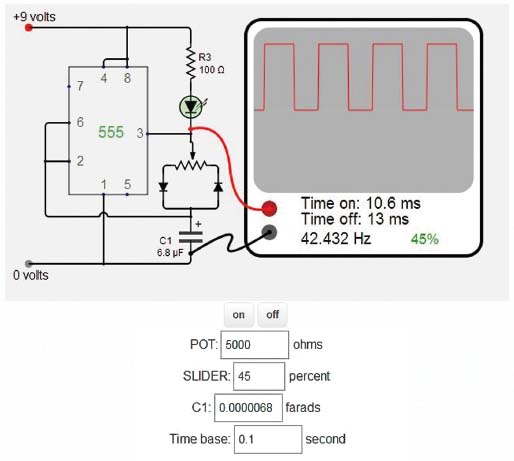
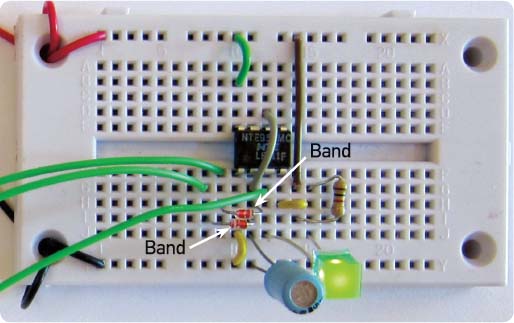
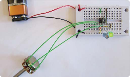
In the schematic diagram shown above (http://artists.sci-toys.com/pwm), the simple circuit has been modified. That previous circuit charged and discharged the capacitor through a single resistor, making the LED blink on for the same amount of time it blinked off. But in this circuit, the resistor has been replaced with a potentiometer and two diodes.
Diodes only conduct electricity in one direction. The two diodes have been arranged so that when the capacitor charges, the electrons flow through the diode on the left. When the capacitor discharges, the electrons flow through the diode on the right.
If you set the slider on the potentiometer all the way to the left (100 percent), then you bypass the resistor altogether and the circuit behaves as if pin 3 were connected to the capacitor directly. Electrons flow from the negative side of the battery (0 volts) through the capacitor, through the diode on the right, and into pin 3, which is connected inside the 555 chip to the positive side of the battery (+9 volts).
This means the capacitor discharges very quickly. In almost no time at all, pin 6 reaches 3 volts and connects pin 3 to the negative side of the battery instead of the positive side. The LED turns on, since electrons can now flow from pin 3, through the LED, and into the positive side of the battery.
The capacitor now charges, as electrons flow from pin 3, through the potentiometer, and through the diode on the right, filling up the capacitor. But since the electrons have to go through all of the resistance of the potentiometer, it takes a while to fill up the capacitor. So the LED is on for a much longer time than it is off. In fact, it looks like it is always on.
If you set the slider on the potentiometer all the way to the right (0 percent), then the situation is reversed. The LED is off all the time.
In between, you can see that the LED is on for a time that corresponds to the percentage of the potentiometer. Since the total resistance of the potentiometer is always the sum of the two sides, the frequency does not change. The only thing that changes is how long the LED is on in each cycle.
If you set the potentiometer slider to 50 percent, the LED is on for half the time, and if the frequency is high enough, the flashes are so brief and close together that you see the light as continuous but only half as bright as when the LED is on all the time.
What have you gained by using this tricky circuit? You gain battery life. The LED is either fully on or fully off and no power is wasted, since you don’t use a current-limiting resistor. You can dim the LED from off to fully on, and almost all of the power the circuit uses is spent making light, not wasted heating up a resistor.
I’d like to make one side note here. You may have noticed that the arrows on the diodes point from positive to negative, the opposite direction that the electrons flow. The choice of which side of the battery to label positive was made before electrons were discovered. It is only an accident of history that the carriers of electric current got labeled negative. But because of that, in electronics we talk about current flow as if positively charged particles were moving from the positive side of the battery to the negative side, when actually electrons move from negative to positive. People talk about conventional current as flowing from positive to negative, but electrons flow from negative to positive. The arrows on the diode symbol reflect this conventional current flow.
The photo above shows the circuit built on a solderless breadboard. I used a 1k-ohm resistor to limit the current for the LED, but smaller values can also be used if you need more light. Below is a close-up of the same photo. You can see the white bands on the two diodes, indicating the direction of current flow. Look at each connection and match it up with the schematic diagram to convince yourself that all of the connections are actually the same, even though the layout looks completely different.