Chapter 16
Advanced Workflows
The Autodesk® AutoCAD® Civil 3D® program is unique in that, with a few exceptions, the data you create is stored in the DWG file. Using data shortcuts will allow you to divide the work among your co-workers and keep your drawing size down. Using data shortcuts will also enable you to keep your existing surface in your topographic survey file and reference it into your design files.
In this chapter you will also look at LandXML as a tool to share data. Using this file format, you can transfer “intelligent” data without a DWG file.
In this chapter, you will learn to:
- Create a data shortcut folder.
- Create data shortcuts.
- Export to earlier releases of AutoCAD.
- Export to LandXML.
Data Shortcuts

A data shortcut is a link between drawings that allows specific types of Civil 3D data to be shared. The shortcut itself does not contain data, but it is a pointer, directing Civil 3D to read information from a common pool of data. A data shortcut is created in the source drawing, and a data reference is the manifestation of the data in a recipient drawing.
There are many situations in which you need data or information to link between drawings. Connections between drawings can be in the form of external references (XRefs), data references, or a combination of the two. These two options are similar but not the same. Table 16.1 compares them.
Table 16.1 XRef vs. data reference
| External reference (XRef) | Data reference |
| For most objects, an XRef is a graphic-only representation of objects created in another drawing. | A data reference is an information/graphic-only link to Civil 3D data created in another DWG file. |
| Any objects (base AutoCAD or Civil 3D) can be displayed in XRefs. | Only specific types of Civil 3D data can be used as data references. |
| Visibility of objects is controlled by original drawing styles and layers. | Visibility of data is controlled by host drawing styles and layers. |
| With the exception of Catchment and Intersection objects, you can use the Civil 3D Add Labels commands on items in an XRef. All other objects (e.g., Surfaces, Alignments, Pipes, Profile Views, etc.) can be labeled through an XRef. | To use Civil 3D object data in design (i.e., using a surface to create an existing ground profile or using an alignment as a corridor baseline), the object must be data referenced. |
| A drawing containing a Civil 3D corridor can be XRef'ed into a host drawing. Sample lines can pull corridor data from the XRef. | A data reference to an alignment in conjunction with an XRef to the corridor enables sample lines to be created in a separate drawing. |
A feature introduced in Civil 3D 2014 brought another important exception to the general rule that external references are “graphics only.” Users now have the ability to use figures, lines, polylines, and feature lines as corridor targets through an external reference.
As noted, only Civil 3D objects can be used with data shortcuts. Not all object types are available through shortcuts. The following objects are available for use through data shortcuts:
- Alignments
- Surfaces
- Profiles
- Pipe networks
- Pressure networks
- View frame groups
Getting Started
When you first create a data shortcut project, you have the option of using a project template. A project template is simply a set of folders, subfolders, and files created to help you keep your file store organized.
In the following exercise, you will create folders for use when creating a data shortcut project:
- Open Windows Explorer and navigate to
C:\Civil 3D Project Templates - Create a new folder titled
MasteringCivil3D - Inside
MasteringCivil3DDesignDocumentsSheetsSurvey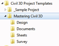
Figure 16.1 Folder structure and standard project files should be included in the project template.
- Locate the file
1601_Project Checklist.docwww.sybex.com/go/masteringcivil3d2016. - Place the file in the
Documents - Locate the file
1601_SheetSetTemplate.dst - Place the file in the
Sheets
This directory structure will appear when a data shortcut project is created. A Documents1601_Project Checklist.docx1601_SheetSetTemplate.dst
A completed version of this set of folders is in the dataset for your reference and is called 1601_MasteringC3D_FINISHED
Setting a Working Folder and Data Shortcut Folder
You can think of the working folder as a project drive. The working folder can contain a number of projects, each with a data shortcut folder where the shortcut files reside.
In this exercise, you'll set the working folder and create a new project:
- Create a new blank drawing using the template of your choice.
You won't save this file, but you do need to have a file open to see the Prospector tab of Toolspace. You need to complete the previous exercise before beginning this one.
- From the Manage tab
 Data Shortcuts panel, click Set Working Folder to display the Browse For Folder dialog, as shown in Figure 16.2.
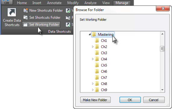
Figure 16.2 Creating a new working folder.
- In the Browse For Folder dialog, on Local Disk (C:), browse to the
Mastering - With the
Mastering - From the Manage tab Data Shortcuts panel, click New Shortcuts Folder to display the New Data Shortcut Folder dialog, shown in Figure 16.3.
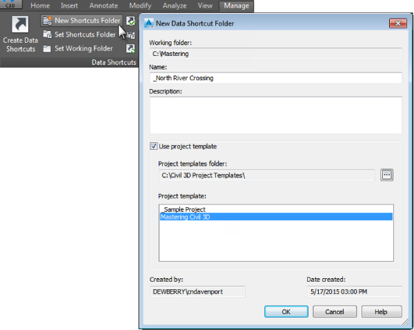
Figure 16.3 Creating a new shortcut folder.
- In the New Data Shortcut Folder dialog, type _North River Crossing for the Name field and click the Use Project Template check box.
- Select the
MasteringCivil3D2016Notice that the Data Shortcuts branch in Prospector now reflects the path of the project you just created, as shown in Figure 16.4.
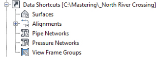
Figure 16.4 The Data Shortcuts area listed in Prospector.
If you open Windows Explorer and navigate to C:\Mastering\_North River Crossing_Shortcuts
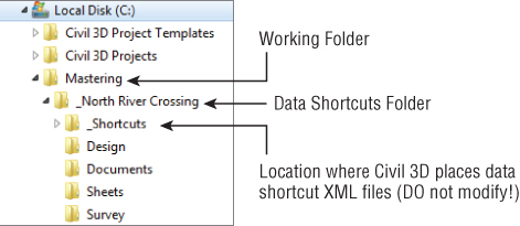
Figure 16.5 Your new project shown in Windows Explorer. Mastering_North River Crossing
In business, your working folder and data shortcuts folder should be on a network drive. If you have an established workflow for creating project folders and don't really need to use the Civil 3D project template, you can do the following:
- Manually create a folder named
_ShortcutsThis folder must be at least two levels deep in your directory structure.

- On the Manage tab Data Shortcuts panel, click Set Working Folder and select a folder two levels above the
_Shortcuts
- On the Manage tab Data Shortcuts panel, click Set Shortcuts Folder and select the folder that is displayed in the Set Data Shortcut Folder dialog, as shown in Figure 16.6.
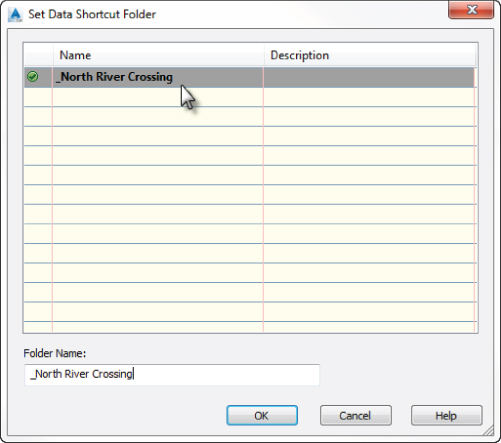
Figure 16.6 Select the folder that contains your manually created
_ShortcutsThis dialog will display only folders that contain a
_Shortcuts
Creating Data Shortcuts
With a shortcut folder in place, it's time to use it. In this exercise, you'll publish data shortcuts for the alignments and layout profiles in your project:
- Open the
1602_ExistingSurface.dwg1602_ExistingSurface_METRIC.dwgThis drawing contains points and an existing ground surface. You need to have completed the previous exercise before continuing.
- From the Application menu, click Save As, and save a copy of this drawing to
C:\Mastering\_North River Crossing\Survey
- From the Manage tab Data Shortcuts panel, click Create Data Shortcuts.
Because the drawing was previously associated to another project, you are presented with a Create Data Shortcuts – Current Project dialog notifying you of this. To continue, you must associate this drawing to the _North River Crossing project.
- Click Close to dismiss the dialog.
- Right-click the Data Shortcuts branch of the Prospector and click Associate Project To Current Drawing.
- Click OK to accept the defaults in the Associate Project To Current Drawing dialog.
- Again, from the Manage tab Data Shortcuts panel, click Create Data Shortcuts.
- In the Create Data Shortcuts dialog, place a check mark next to Existing Surface, as shown in Figure 16.7, and click OK.

Figure 16.7 Adding surface data to data shortcuts.
- Save and close the current drawing file.
- Open the
1602_Alignments-Profiles.dwg1602_Alignments-Profiles_METRIC.dwgThis file contains five alignments that you will add to the data shortcut project.
- From the Application menu, click Save As, and save a copy of this file to
C:\Mastering\_North River Crossing\Design - Repeat steps 5 and 6 to reassociate the drawing to the _North River Crossing project.
- From the Manage tab Data Shortcuts panel, click Create Data Shortcuts.
- In the Create Data Shortcuts dialog, place a check mark next to the Alignments collection, which will select all the alignments and profiles if any exist (as shown in Figure 16.8), and click OK.
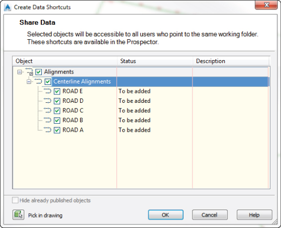
Figure 16.8 Adding alignment data to the pool of data shortcuts.
You should now have surfaces and alignments available for use in the data shortcuts list in Prospector, as shown in Figure 16.9. Notice in Figure 16.9 how highlighting the data shortcut in the list reveals the source location at the bottom of Toolspace.
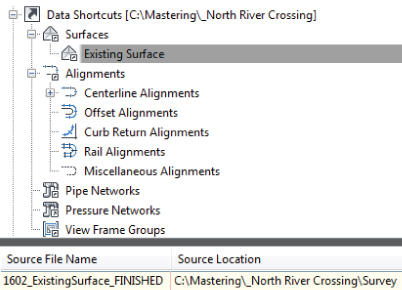
Figure 16.9 List of Civil 3D data shortcuts available to the current project.
Keep 1602_Alignments-Profiles.dwg1602_Alignments-Profiles_METRIC.dwg
Creating a Data Reference
Now that you've created the shortcut files to act as pointers back to the original drawing, you'll use them in other drawings. In this section, you will create and use data references.
Data references are made using the Data Shortcuts branch within Prospector. In this exercise, you'll create a reference to the surface you previously shared to the project.
You need to have completed the previous exercises to continue.
- Keep working in
1602_Alignments-Profiles.dwg1602_Alignments-Profiles_METRIC.dwg - In Toolspace, expand the Prospector Data Shortcuts Surfaces collection, right-click Existing Surface, and select Create Reference, as shown in Figure 16.10.
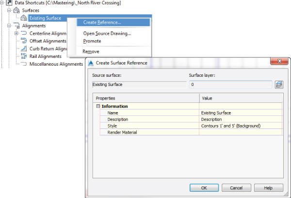
Figure 16.10 The Create Surface Reference dialog.
- In the Create Surface Reference dialog, leave all surface options at their defaults and click OK. Zoom extents to view the surface.
- Save the current drawing and keep it open for the next exercise.
You should now see the surface in the drawing. At first glance, it does not look different from other surfaces you've worked with within Civil 3D. If you examine the Surfaces branch of Prospector, however, you'll see that there is no Definition collection (as shown in Figure 16.11). You cannot edit a surface or any other object that is data referenced. If a change needs to be made to Existing Surface, you would need to open the drawing file where it was originally created.
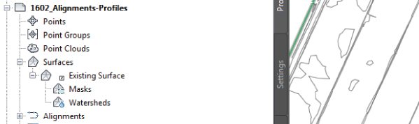
Figure 16.11 You can see and use the surface, but you cannot add to or edit the surface definition.
Any changes to the surface will be communicated through the data shortcut to the drawings where it is referenced. If the drawing is open when a data-referenced source file has been changed, a bubble message will pop up to inform the user that the item must be synchronized to view the most up-to-date information. If a recipient drawing is closed at the time the change takes place, all data references will automatically be synchronized as the file opens.
In the next part of the exercise, you will use the skills you learned in Chapter 7, “Profiles and Profile Views,” to create an existing ground profile and a design profile. After you have all the information, you will use skills from Chapter 9, “Basic Corridors,” to put the information together. You need to have completed the previous exercises to continue.
- Keep working in
1602_Alignments-Profiles.dwg1602_Alignments-Profiles_METRIC.dwg - Select the ROAD A alignment.

- In the Alignment contextual tab Launch Pad panel, click Surface Profile.
- In the Create Profile From Surface dialog, do the following:
- Click Add.
- Click Draw In Profile View.
- In the Create Profile View dialog, click Create Profile View, and click to place the profile view anywhere in the drawing to the right of the surface.

- Select the profile view. From the Profile View contextual tab Launch Pad panel, click Profile Creation Tools.
- In the Create Profile – Draw New dialog, name the new profile FG-ROAD A.
- Set Profile Style to Design Profile and click OK.

- From the Profile Layout Tools, click Insert PVIs Tabular.
- Enter the data for your unit system, as shown in Figure 16.12; then click OK.
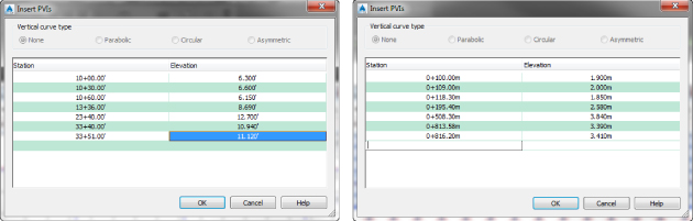
Figure 16.12 Profile data Imperial (left) and Metric (right).
You can close the Profile Layout Tools toolbar when finished.
- Save the drawing.

- From the Manage tab Data Shortcuts panel, click Create Data Shortcuts.
- Place a check mark next to Profiles, as shown in Figure 16.13, and click OK.
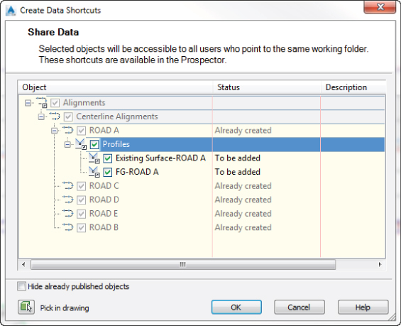
Figure 16.13 Adding additional drawing data to the data shortcut project.
The alignments that you added earlier are listed but are grayed out. Once you add an item to the Data Shortcut list, you do not need to add it again. Only new data will be added to the list of data shortcuts. Shown in gray will be the list of items that are already published as data shortcuts. If you find the list of already published items distracting, you can hide all of the published items by clicking the Hide Already Published Objects check box at the bottom of the dialog.
- Save and close
1602_Alignments-Profiles.dwg1602_Alignments-Profiles_METRIC.dwg - From your class files, open
1603_Corridor.dwg1603_Corridor_Metric.dwg - From the Application menu, click Save As, and save the drawing to
C:\Mastering\_North River Crossing\Design - From the Prospector tab of Toolspace, expand the Data Shortcuts branch and then expand Surfaces.
- Right-click Existing Surface and click Create Reference.
- In the Create Surface Reference dialog, leave all default settings and click OK.
- From the Prospector tab of the toolbar, expand the Data Shortcuts branch and then expand Alignments Centerline Alignments ROAD A Profiles.
- Right-click FG-ROAD A and select Create Reference, as shown in Figure 16.14.
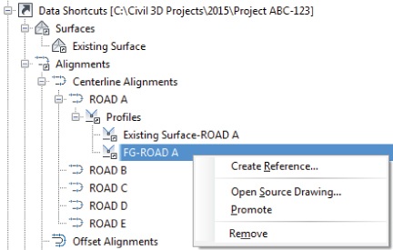
Figure 16.14 Creating a data reference to a profile will automatically create a data reference for its alignment.
- In the Create Profile Reference dialog, change Profile Style to Design Profile and click OK.
If you zoom extents in the drawing, you should see the alignment and existing surface.
The profile data is referenced but is not currently visible. If you wanted to, you could create a profile view. However, you do not need the profile to be visible to create a corridor.
- From the Home tab Create Design panel, click Corridor. In the Create Corridor dialog, do the following:
- Name the corridor ROAD A.
- Verify that the alignment is set to ROAD A.
- Verify that the profile is set to FG-ROAD A.
- Set the assembly to Basic Assembly.
- Set Target Surface to Existing Surface.
- Clear the check box for Set Baseline And Region Parameters.
- Click OK.
- Close the Panorama before proceeding.
- After the corridor builds successfully, save and close the drawing; you will come back to it later.
Updating References
When you need to make a change, you can use the tools in the Data Shortcut menu to jump back to that file, make the changes, and refresh the reference.
- If it is not open from the exercise in “Creating Cross-Section Sheets in Their Own Drawing,” open the file
1604_Sections.dwgIdeally, you saved it to
C:\Mastering\_North River Crossing\Sheets - Keep this drawing open and also open the file
1603_Corridor.dwg - In Prospector, expand Data Shortcuts Surfaces.
- Right-click Existing Surface and select Open Source Drawing, as shown in Figure 16.15.
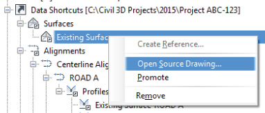
Figure 16.15 Open Source Drawing is a fast way to jump to the drawing you want.
At this point, you should have three drawings open (
1602_ExistingSurface1603_Corridor1604_Sections1602_ExistingSurface_METRIC1603_Corridor_METRIC1604_Sections_METRICThe
1602_ExistingSurface.dwg1602_ExistingSurface_METRIC.dwg)In this drawing, you will add polyline contours to the surface definition. The change to the surface will affect all drawings where the surface is used as a data reference. The dynamic communication between drawings shows the power of the Data Shortcut tool.
- Select the surface in the drawing window.

- On the contextual ribbon Modify panel Add Data tool, select Contours.
- In the Add Contour Data dialog, under Description, enter Mound and click OK.
- In the drawing window, select the green polyline contours with a crossing selection box.
- Press Enter when finished.
- Save and close
1602_ExistingSurface.dwg1602_ExistingSurface_METRIC.dwg - Switch drawings so that
1603_Corridor.dwg1603_Corridor_METRIC.dwgShortly after bringing this drawing to the forefront, you should see an alert symbol appear on the external reference icon on the status bar indicating that data shortcut definitions may have changed, as shown in Figure 16.16.
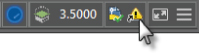
Figure 16.16 Civil 3D will send the user a message when a data-referenced object has changed.
- Right-click and click Synchronize.

In some situations, you see a warning symbol in the Prospector. In that case, you can always synchronize directly from the right-click menu of the referenced object, as shown in Figure 16.17.
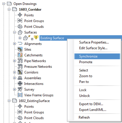
Figure 16.17 Synchronizing from the object's right-click menu.
You may receive a message in Panorama indicating that the item was synchronized.
- Dismiss this message by clicking the green check box.
The surface that changed is used as a target in the corridor; therefore, the corridor needs to be rebuilt.
- Expand Prospector Corridors, right-click the ROAD A corridor and select Rebuild.
- Save and close
1603_Corridor.dwg1603_Corridor_METRIC.dwg - Switch to
1604_Sections.dwg
This time, you will receive a message that your external reference file has changed, as shown in Figure 16.18. If you accidentally dismiss this message without updating, a warning symbol will remain in the tray area at the bottom of your screen. You can always right-click to reload the reference from this icon.
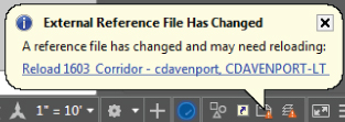
Figure 16.18 Reload the external reference to ensure your cross sections reflect the design update.
- Zoom to the section view at station 16+00 (0+300 if metric) and take a look at the section line representing Existing Surface.
- Click Reload 1603_Corridor or 1603_Corridor_METRIC if metric in the External References dialog.
Your sections should now reflect all the design changes. If you receive a message regarding unreconciled layers, click the X to dismiss it.
- Save and close all drawings.
You can find a completed version of the project folder with updates with this chapter's dataset. The folder is called _North River Crossing
Fixing Broken References and Drawing Associations
A broken reference is fairly easy to fix, but you will not be able to continue working in your design until broken references are resolved.
Actions that will cause broken references include the following:
- Renaming a source file
- Moving a source file
- Missing a source file
- Renaming project folders
In the following exercise, you will associate drawings that have been renamed to a project that has been renamed and fix the broken data references that you find. You do not need to have completed the previous exercises to continue.
- Using Windows Explorer, locate the folder called
_Broken ReferenceThis is part of the download for this chapter at the book's web page.
- Copy this folder and its contents to
C:\Mastering - Open the
1605_Corridors.dwgC:\Mastering\_Broken Reference\DesignThis file contains a number of references pointing to files that have been renamed. Panorama may appear with the messages regarding the problems that it found.
- If it's open, close the Panorama window by clicking the green check mark.
- On the Manage tab Data Shortcuts panel, click Set Working Folder:
- Set the working folder to
C:\Mastering - Click OK to close.
- Set the working folder to
- On the Manage tab Data Shortcuts panel, click Set Shortcuts Folder:
- Select
_Broken Reference - Click OK to close.
- Select
- In Prospector, locate the Data Shortcuts branch and expand Surfaces.
Because the Shortcuts project folder was renamed, the shortcuts in the project need repairing.
- Under the Data Shortcuts branch in the Prospector, right-click Existing Surface and click Repair Broken Shortcut.
- In the Choose The File Containing The Referenced Object dialog, browse to the
1605_ExistingSurface.dwgC:\Mastering\_Broken Reference\Survey - In Prospector, expand Data Shortcuts branch Alignments Centerline Alignments.
- For ROAD A, right-click and click Repair Broken Shortcut.
- In the Choose The File Containing The Referenced Object dialog, browse to the
1605_Alignments-Profiles.dwgC:\Mastering\_Broken Reference\Design - In the Additional Broken Shortcuts dialog, click Repair All Broken Shortcuts.
- Back up in the drawing collection in Prospector, expand Alignments Centerline Alignments. You will see that next to ROAD A is a warning chevron.
- Right-click ROAD A and select Repair Broken References, as shown in Figure 16.19.
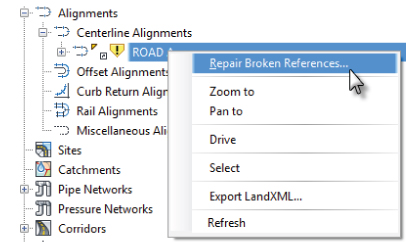
Figure 16.19 Choosing Repair Broken References.
After fixing the first broken reference, if more broken references exist, you will be prompted to fix them in the Additional Broken References dialog, shown in Figure 16.20.
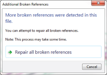
Figure 16.20 The Additional Broken References message.
- Click Repair All Broken References.
- Close the current drawing. You may save it, but you will not need it for additional exercises.
The ability to repair broken links helps make file management a bit easier, but there will be times when you need to completely change the path of a shortcut to point to the correct file. To do so, you must use the Data Shortcuts Editor.
The Data Shortcuts Editor
A Civil 3D drawing stores links to the information it uses in its database. The Data Shortcuts Editor is used to update or change the file to which a shortcut points. You may want to do this when preparing a deliverable.
In the following exercise, you'll copy the current chapter project to another folder and update the data shortcut paths with the Data Shortcuts Editor (the procedure is the same for both metric and Imperial units):
- Using Windows Explorer, locate the folder called
_DeliverableThis is part of the download for this chapter at the book's web page.
- Copy this folder and its contents to
C:\Mastering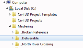
Figure 16.21 Simulating a new project phase by copying the example project to a new folder.
Next, you will open the Data Shortcuts Editor to correct the file paths in the _
Deliverable
- In Windows, choose Start All Programs Autodesk Autodesk AutoCAD Civil 3D 2016 – English and click the Data Shortcuts Editor to load it.
- Select File Open Data Shortcuts Folder to display the Browse For Folder dialog.
- Browse to
C:\Mastering_DeliverableYour Data Shortcuts Editor should resemble Figure 16.22.
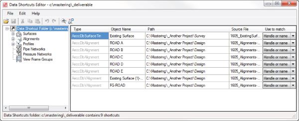
Figure 16.22 Inside the Data Shortcuts Editor.
Several things need to be changed before the new phase of the project can begin. Some of the data references are looking for the incorrect file.
Notice that the Path column of the table still refers to the old path. To make a clean break from the old project to move forward into the
Submitted - Click to set your cursor into the Path field for Existing Surface.

- Choose Find And Replace.
Unfortunately, there is no browse option here, but you can use the basic Windows Copy and Paste tools to make this a little easier.
- Delete
\Survey - Paste the path into the Replace With field.
- In the Replace With field, replace the text
_Another Project_Deliverable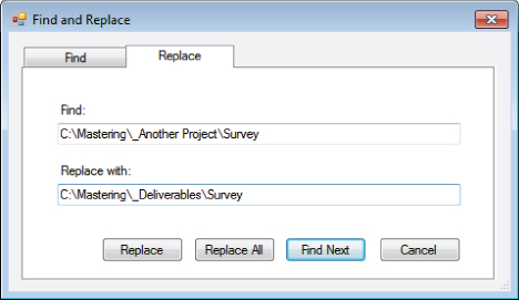
Figure 16.23 Updating the paths to the new project.
- Click Replace All.
Your data shortcut paths are now correct (as shown in Figure 16.24) and ready for more action. Click Cancel to close the Find And Replace tool.

Figure 16.24 Updated paths.
- Click Cancel to close the dialog.
- Click the Save icon to commit your changes.
- You can now close the Data Shortcuts Editor and return to Civil 3D.
Sharing Data with a Non–Civil 3D World
Not everybody uses Civil 3D 2016, so you need to know how to convert your drawing files and extract your design data for those people who are using previous versions of AutoCAD or different land development software.
Delivering DWG Formats
Files created in Civil 3D 2016 are backward compatible to Civil 3D 2014. Currently, these are the only two versions that will work together without losing significant amounts of data. Even though Civil 3D 2014 was said to be backward compatible with Civil 3D 2013, it is not advisable to use them together.
The Save As command can be misleading for Civil 3D users. Keep in mind that the Save As command works only on AutoCAD objects such as lines, arcs, and circles—not Civil 3D objects. To save to a version of Civil 3D 2012 or prior, you will need to use the Application menu ![]() Export
Export ![]() Export Civil 3D Drawing. This is a new command in Civil 3D 2016. The result will be exploded Civil 3D objects.
Export Civil 3D Drawing. This is a new command in Civil 3D 2016. The result will be exploded Civil 3D objects.
In the following exercise, you will export a Civil 3D 2016 corridor model to an AutoCAD 2010 file format:
- Open
C:\Mastering\_North River Crossing\Design\1603_Corridor.DWGFor this exercise, you need to have completed the
_Deliverable - From the Application menu, click Export Export Civil 3D Drawing.
- In the Export AutoCAD Civil 3D Drawing dialog, click the Export Settings button.
- Under DWG File Version, select 2010 from drop-down menu.
- Click OK to close.
Note the settings for the treatment of external references.
- Under Files To Export, click Selected Drawings In Source Folder and select the check box next to Include Drawings In Subfolders.
- On the right side of the dialog under Source Folder, click the ellipsis button next to the field.
- In the Browse For Folder dialog, select the
_Deliverable - Click OK to close the dialog.
- In the Browse For Folder dialog, select the
- Under Destination Folder, click the ellipsis button next to the field.
- In the Browse For Folder dialog, select the
_Deliverable - Click the Make New Folder button at the bottom of the dialog.
- For the new folder name, type 2010 DWG Files.
- Click OK to close the dialog.
- In the Browse For Folder dialog, select the
- Uncheck the check box next to Include Sheets. Leaving it filled will export the layouts as separate drawing files.
The Export AutoCAD Civil 3D Drawing dialog should look like Figure 16.25.
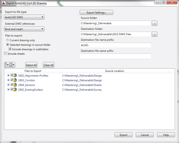
Figure 16.25 Export AutoCAD Civil 3D Drawing dialog, a new feature in Civil 3D 2016.
- Click Export.
The export may take a few minutes.
- When the Export Status dialog reads 4 Of 4 Files Exported, click OK to close even though the green progress bar is still animated.
- Click Cancel to close the Export AutoCAD Civil 3D Drawing dialog.
- Open
C:\Mastering\_Deliverable\2010 DWG Files\survey\ACAD-1602_ExistingSurface-Model.dwgACAD-1602_ExistingSurface_METRIC.dwgAs the file opens, the command line will echo
Opening An AutoCAD 2010/LT 2010 Format File - Click a contour.
This export command will explode all objects to AutoCAD entities. The contour is now a polyline and has taken on the layer assigned to it through the style once assigned to it. It also forces color, linestyle, lineweight, and any properties overrides in the styles to the resulting entities.
- Press Esc to deselect the contour.
- Close the drawing without saving. You don't want to upgrade the file format.
- Close all the drawings.
Compare the content of your 2010 DWG Files2010 DWG Files_FINISHED
Using LandXML
LandXML is not specific to Civil 3D. It is a file format that allows users to share data in a nonproprietary format. You can use LandXML to archive projects and to send information to non–Civil 3D users or users of Civil 3D using 2012 or earlier.
A drop-down in the Import LandXML dialog lets you select the version of LandXML. This is a result of that consortium. The latest, as of this writing, is the 1.2 schema. Most CAD programs have methods of importing and exporting LandXML files, and this is one way to tackle that barrier.
Alas, the need to send data to older versions of Civil 3D is not always avoidable. In the following exercise, you will step through an example of what needs to happen to force Civil 3D to previous versions:
- Open
1606_LandXML-OUT.dwg1606_LandXML-OUT_METRIC.dwg
- From the Output tab Export panel, select Export To LandXML.
The Export To LandXML dialog, shown in Figure 16.26, opens.
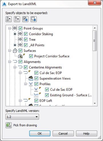
Figure 16.26 The Export To LandXML dialog.
- Click OK.
- In the Export To LandXML dialog, browse to the same folder as the source drawing.
- Keep the default name (the dialog will pick up the name of the drawing you are exporting from) and click Save.
You now have as much Civil 3D as possible packed up into the LandXML file. This file contains the following:
- Alignments
- Point groups and points
- Surfaces
- Profiles
- Pipe data
If you are ever sent a LandXML file, you will need to import the contents into a file created from your Civil 3D template.
- Create a new drawing using the template of your choice.
- On the Insert tab Import panel, click LandXML.
- In the Import LandXML dialog, browse for and select the XML file you created in steps 4 and 5; click Open.
Figure 16.27 shows the Import LandXML dialog.
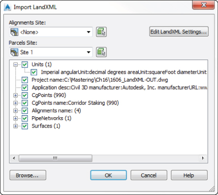
Figure 16.27 Importing LandXML data.
- Click OK.
- Dismiss Panorama if it's open.
- Browse Prospector for the data that was imported.
At this point you could change styles and apply label styles to certain objects.
- Save and close the drawing.
You can find completed versions of the resulting file after LandXML import with this book's dataset. Compare your work with 1606_LandXML-IN_FINISHED.dwg1606_LandXML-IN_METRIC_FINISHED.dwg
The Bottom Line
- Create a data shortcut folder. The ability to load design information into a project environment is an important part of creating an efficient team. The main design elements of the project are available to the data shortcut mechanism via the working folder and data shortcut folder.
- Master It Using the
MasterIt1601.dwgMasterIt1601_METRIC.dwgMasterIt_Sample Project
- Master It Using the
- Create data shortcuts. To allow sharing of the data, shortcuts must be made before the information can be used in other drawings.
- Master It Continue working in the drawing from the previous “Master It” exercise. Save the drawing to the
Source DrawingsMasterIt1601.dwgMasterIt1601_METRIC.dwg
- Master It Continue working in the drawing from the previous “Master It” exercise. Save the drawing to the
- Export to earlier releases of AutoCAD. Being able to export to earlier base AutoCAD versions is sometimes necessary.
- Master It Using
MasterIt1601.dwgMasterIt1601_METRIC.dwg
- Master It Using
- Export to LandXML. Being able to work with outside clients or even other departments within your firm that do not have Civil 3D is an important part of collaboration.
- Master It Using
MasterIt1601.dwgMasterIt1601_METRIC.dwg
- Master It Using