CHAPTER 10
Stairs, Ramps, and Railings
A whole chapter just for stairs, ramps, and railings? You bet! If you think about it, there could be hundreds of combinations of stair and railing systems. As a matter of fact, you very seldom see two sets of stairs that are exactly the same. Kind of like snowflakes, aren't they? OK, they're nothing like snowflakes! But you get the point.
This chapter covers the following topics:
- Creating stairs by using the Rise/Run function
- Creating a winding staircase
- Creating a custom railing system
- Creating custom stairs
- Adding ramps
Creating Stairs by Using the Rise/Run Function
To begin, this chapter will address the makings of a staircase—from commercial stairs to those with a more residential feel, with wood members, balusters, and spindles. During this procedure, you'll see how the Autodesk® Revit® software brings stairs together. After you create a common staircase, you'll move on to winding stairs, custom railings, and, of course, ramps.
In this section, you'll focus on creating a staircase by using the traditional Rise/Run method. Then I'll discuss modifying the boundary of the stairs, which allows you to create a more unusual shape than that provided out of the box.
To begin, open the file you've been using to follow along. If you didn't complete Chapter 9, “Ceilings and Interiors,” go to the book's web page at www.wiley.com/go/revit2020ner. From there you can browse to the Chapter 10 folder and find the file called NER‐10.rvt.
The objective of the following procedure is to create a staircase using the Rise/Run method:
- In the Project Browser, go to the Level 2 floor plan.
- Zoom in on the radial entry in the east wing, as shown in Figure 10.1.
- On the View Control bar, change Visual Style to Hidden Line.
- On the Circulation panel of the Architecture tab, click the Stair button (see Figure 10.1).

FIGURE 10.1 Click the Stair button on the Circulation panel of the Architecture tab.
You're put into Sketch mode for the stairs you're about to design, as shown in Figure 10.2.
- On the Components panel of the Modify | Create Stair tab, make sure the Run button is checked.
- On the Options toolbar, set the Location Line to Exterior Support: Left.
- Set the offset to ‐6″ (‐152 mm).
- Set Actual Run Width to 4′‐0″ (1219.2 mm) (see Figure 10.2).
- In the Properties dialog, change Base Level to Level 1.

FIGURE 10.2 The Modify | Create Stair tab, Sketch mode
- Change Top Level to Level 2 (see Figure 10.3).

FIGURE 10.3 Changing the element properties of the stairs
Now it's time to physically model the stairs. What we need to do is start picking points and Revit will start guiding us. This specific staircase will have two sections and a landing at the halfway point. To start adding the stairs, follow these steps:
- Pick point 1 in Figure 10.4. It is the center of the column.
- Once the point is picked, move your cursor to the right. Notice that you get a temporary dimension at the top of the stair run and a display at the bottom telling you how many risers are created and how many remain.
- Once you get to 9′‐2″ (2794 mm) and it says “11 risers created, 10 remaining,” pick the point labeled 2 in Figure 10.4.

FIGURE 10.4 Adding the first run
- Move your cursor straight up (north) until you get to the grid intersection labeled 3 in Figure 10.5. When you see this, pick the third point. Note that you need to keep your cursor perfectly aligned with the edge of the stair run you just placed. You should see a green dotted alignment line indicating that you are good.
- Move your cursor to the left—all the way past the floor landing. Revit reports that you have 10 risers created and 0 remaining, as shown in Figure 10.6.
- When the second leg is completed, pick the last point. Revit draws both runs as well as the landing (see Figure 10.6).

FIGURE 10.5 Move your cursor straight up.

FIGURE 10.6 Move your cursor to the left. It's good to go way past the actual run. Revit will add only the necessary risers.
With the basic layout completed, it's time to examine the perimeter of the stairs. If you're looking for any architectural design outside of the basic box that you get when you place a staircase, you'll want to edit the boundary.
Modifying Boundaries
With the main stairs in place and laid out, you can now start modifying the profile. Given that this is a five‐tiered, multilevel staircase, the boundary will be somewhat limited—but not to the point that you can't make something pop out of your design.
To modify the boundary, follow along:
- Select the landing, as shown in Figure 10.7.
- Click the Convert button (see Figure 10.7).

FIGURE 10.7 The Convert button
- When you see the warning that you may be doing irreversible damage, click Close to dismiss it.
- With the landing still selected, click the Edit Sketch button, as shown in Figure 10.8.

FIGURE 10.8 The Edit Sketch button
- On the Draw panel, click the Start‐End‐Radius Arc button, as shown in Figure 10.9.
- Draw an arc on the outside of the landing at a 12′–0″ (3658 mm) radius (see Figure 10.9).
With the radius drawn in, it's important to pause at this point. What you have here is an extra line. Similar to when you're sketching a floor, if you have any overlapping line segments or gaps, Revit won't let you continue. Also, if you have any extra lines, Revit won't let you continue.
Let's clean up the stairs:
- Click Modify or press the Esc key twice, and then select the straight green line at the outside of the landing.
- Press the Delete key on your keyboard. The line is removed. Your stairs should look exactly like Figure 10.10.
- Click the Finish Edit Mode button, as shown in Figure 10.11.

FIGURE 10.9 Add a radius to the outside of the landing.

FIGURE 10.10 The completed boundary

FIGURE 10.11 Finishing the sketch
Now you can select the railing system to use. Out of the box, Revit provides only four choices. You'll select one of those for this staircase, but you'll add to the list later in this chapter.
Configuring Railings
Revit provides a small number of railing systems as defaults. You can choose one of these five railings to apply to the staircase during the Sketch mode of the stairs.
Follow this procedure to apply a railing to the stairs:
- On the Modify | Create Stair tab in Sketch mode, click the Railing button, as shown in Figure 10.12.
- In the Railing dialog, from the drop‐down select Handrail ‐ Pipe, as shown in Figure 10.12.
- Under Position, keep the Treads radio button selected (see Figure 10.12). Doing so hosts the railing to the treads.

FIGURE 10.12 Adding a more handsome railing
- Click OK. With the railings in place, you're on your way to completing this staircase. As a matter of fact, round one is finished.
- To complete the stairs, click Finish Edit Mode on the Modify | Create Stair tab.
- You'll get a warning that the rail is not continuous. That's OK. We'll drill into railings later. Click the red X.
- Go to Level 2. Your stairs should look like Figure 10.13.
Uh‐oh! We have a serious ankle breaker where the DN (Down) text is. There's a gap between the stairs and the floor. Luckily, we have a simple solution to fix this. We're going to move the entire staircase to the left.
- Select the stairs and click the move button as shown in Figure 10.14.
- Pick the endpoint as shown in Figure 10.14.
It's kind of weird what we need to do here. The problem is, we are going to modify the railings to extend past the first riser for Americans with Disabilities Act (ADA) compliance. We are also going to turn this staircase into a multilevel staircase. In Revit, however, when we modify the railings on a multistory staircase, it will change the railing on every level. That's a good thing if you want that to happen, but a bad thing if you don't. To get around that, we are going to have to copy and paste the Level 1 stair to Level 3.

FIGURE 10.13 The stairs as displayed in the plan

FIGURE 10.14 Move the stairs to align with the face of the floor edge
- Go to Level 2.
- Select the stairs, as shown in Figure 10.15.
- On the Clipboard panel, pick the Copy To Clipboard button, as shown in Figure 10.15.
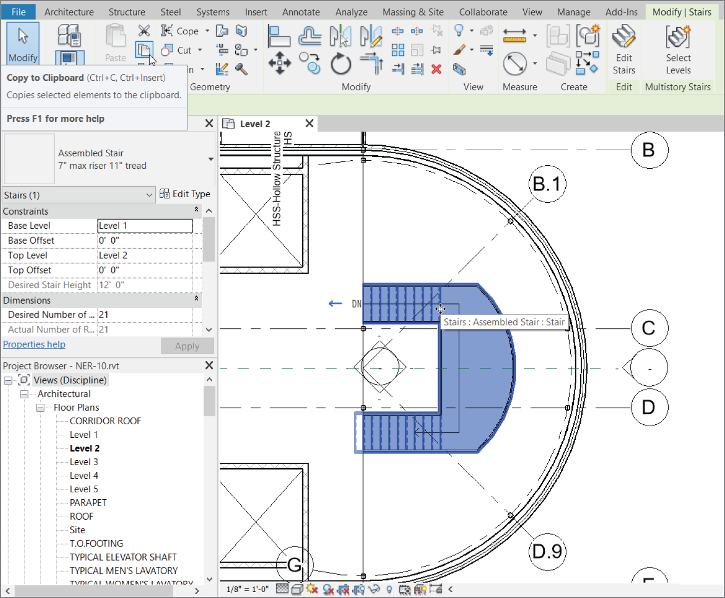
FIGURE 10.15 Select the stairs and click the Copy To Clipboard button.
- Next to the Copy button is the Paste button. It was just inactive (grayed out), but now it is in color. Just below the icon is a small down arrow. Click that.
- Select Aligned To Selected Levels.
- Choose Level 3 and click OK. See Figure 10.16.
- Go to Level 3.
- Cut a section as shown in Figure 10.17 and rename it to SECTION AT STAIRS.
- Press Esc, and open the section by double‐clicking the bubble.
- Select the stair on Level 3, as shown in Figure 10.18.
- Click the Select Levels button.
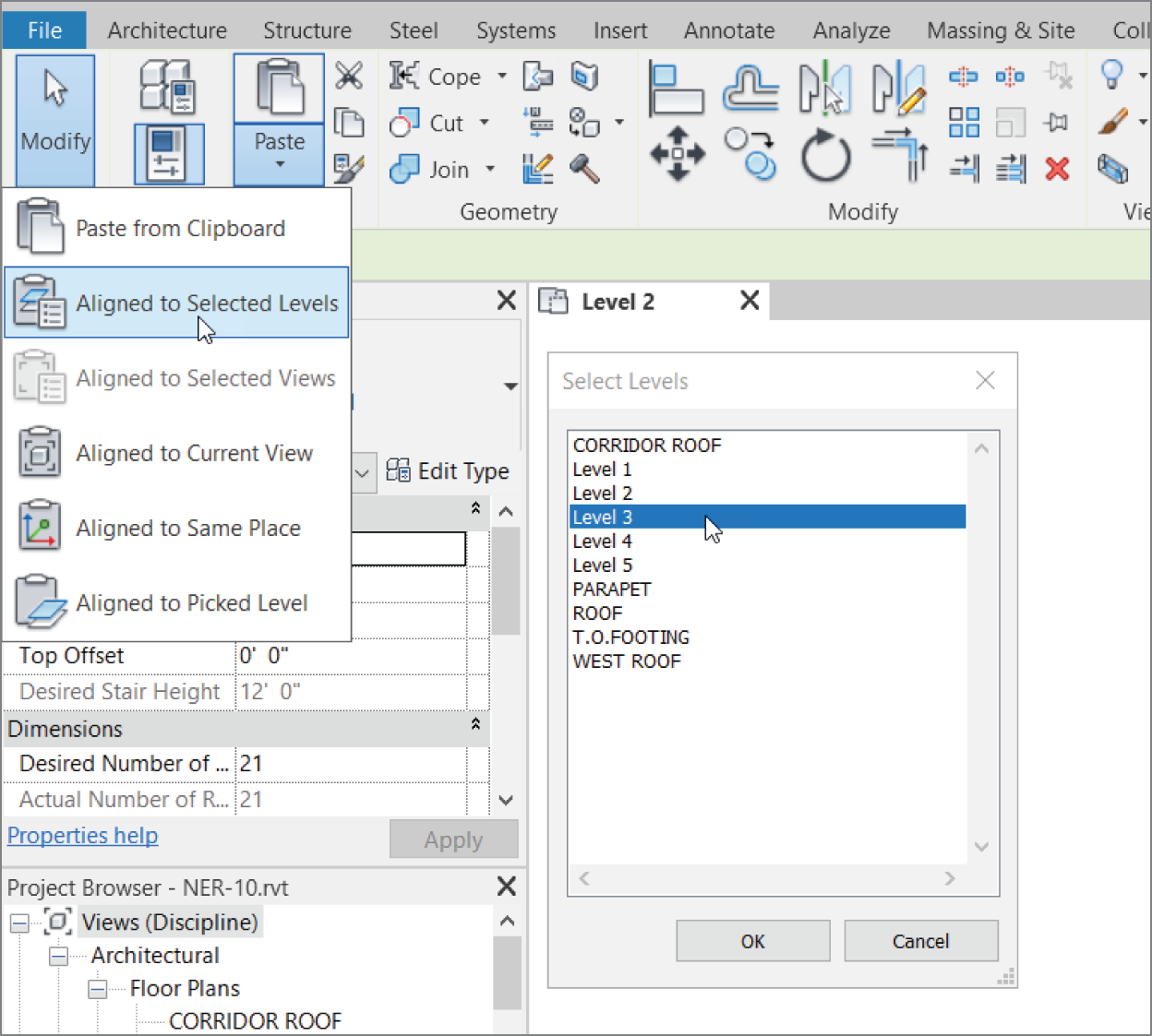
FIGURE 10.16 Paste: Aligned To Selected Levels – Level 3

FIGURE 10.17 Adding the SECTION AT STAIRS section

FIGURE 10.18 Connecting levels
- Hold down the Ctrl key and select Levels 4 and 5.
- Click the green Finish Edit Mode button. Your stairs should look like Figure 10.19.

FIGURE 10.19 Lookin' good!
- Hover your cursor over the stairs that are on Levels 3–5. Notice the box that appears indicating that the stairs are connected.
- When you see that box, pick the stairs.
- Hold down the Ctrl key and select the stairs on the First Floor.
- Click the Selection Box button, as shown in Figure 10.20.
You now have a 3D view that is cropped to your stairs.

FIGURE 10.20 Creating a selection box
- Select the wireframe box that is cropping your view, as shown in Figure 10.21.
- Rename the {3D} view in the Project Browser to ENTRY STAIRS.
- Select the grip at the top of the box and stretch the box up so that you can see the roof (see Figure 10.21).
- Click the Default 3D view icon on the Quick Access toolbar. This will regenerate the {3D} view.
Here's a problem: the railing just stops dead at the bottom of the stringer. This may have been acceptable practice around the time, say, when the wheel was still on the drawing board. You need some kind of railing extension. To accomplish this, follow along with the next procedure.
- Go to Level 2.
- Zoom into the bottom run of the stairs (near the UP text).
- On the Architecture tab, click the Reference Plane button, as shown in Figure 10.22.

FIGURE 10.21 Renaming {3D} and stretching the box

FIGURE 10.22 Click the Ref Plane button.
- On the Draw panel, click the Pick Lines button.
- Offset a reference plane 1′‐6″ (457 mm) to the left of the bottom riser (see Figure 10.23).
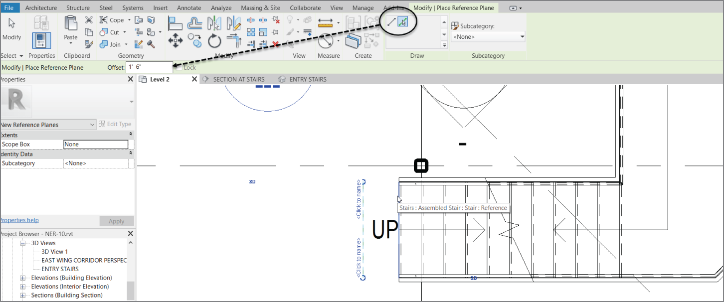
FIGURE 10.23 Placing the reference plane
Extending the Railings
Now we have to physically extend the railing. The problem is, we don't know exactly how far the railing needs to extend past the first riser at the specific angle of the stairs. By offsetting the reference plane 1′‐6″ (457 mm), we can be assured that the railing will extend far enough at that angle to hit the 3′‐0″ railing height before it goes flat to meet the floor. This procedure has actually been modified several times over the years. It's actually pretty easy!
- In the level 2 floor plan, select the bottom railing, as shown in Figure 10.24. Make sure you aren't selecting the stairs.
- Click Edit Path, as shown in Figure 10.24.
- On the Options panel, click the Preview button.
- Select the grip at the end of the magenta line representing the railing, and drag it to the left until it meets the reference plane you placed previously. (See Figure 10.25.)
- Click the green Finish Edit Mode check mark.
- Go to the ENTRY STAIRS 3D view.
- Select the section box, and drag the left grip further to the left and to the right so you can see your railing. (See Figure 10.26.)

FIGURE 10.24 Select the railing and click Edit Path.

FIGURE 10.25 Drag the railing to the left.
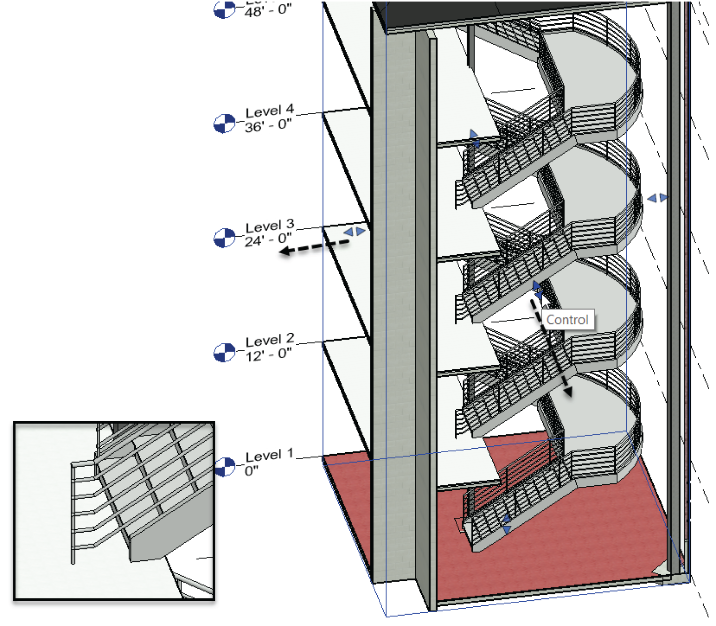
FIGURE 10.26 Checking out the railing extension
- Repeat the procedure with the middle railing, as shown in Figure 10.27.

FIGURE 10.27 Both railings extended
Further Modifying the Railings
What is cool about this now is the fact that we can keep making edits to these railings and the edits will be displayed from Floor 2 to Floor 5, leaving Floor 1 to perform some different edits.
Let's continue editing the bottom railing:
- In the Project Browser, go to the Level 2 floor plan.
- Select the bottom railing and click Edit Path.
- On the Draw panel, make sure the Line button is checked.
- Draw a line straight down to meet the wall, as shown in Figure 10.28.
- On the Draw panel, click the Fillet Arc button.
- Click the Radius button on the Options toolbar, as shown in Figure 10.28, and add a 3″ (76 mm) radius.
- Click points 1 and 2, as shown in Figure 10.28.

FIGURE 10.28 Finishing off the railing
- Click Finish Edit Mode and check out your railing in the 3D view.
- Go back to Level 2 and select the inside railing.
- Click Edit Path.
- Extend the railing to the reference plane identical to the bottom railing.
- Draw a new rail line to stop at grid line C.
- Add a 3″ (76 mm) fillet arc the same as you did on the bottom railing (see Figure 10.29).

FIGURE 10.29 Completing the middle railing
- Click the green Finish Edit Mode check mark.
- Right‐click on the railing and select Create Similar.
- Draw a railing as shown in Figure 10.30.
- Mirror the railing you just modeled to the upper railing on the stairs, as shown in Figure 10.31.
- Select the mirrored railing and click Edit Path.
- Drag the end of the railing to the wall, as shown in Figure 10.31.
- Click the green Finish Edit Mode button.
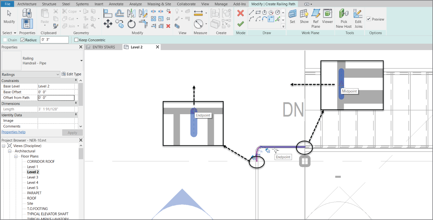
FIGURE 10.30 Adding a stand‐alone railing

FIGURE 10.31 Adding the railing to the north
The reason we had to do that was because if we had just modified the existing railing that is on the stairs, we would have formed a closed loop, which would have made the railing jump off the staircase. Modeling the railings separately makes it so that doesn't occur.
The next step is to copy and paste the independent railings to the floors above. We'll have to make some adjustments to the pasted railings on Level 5 when we get there.
- Go to the 3D view ENTRY STAIRS.
- Select the two independent railings you just modeled.
- Click the Copy To Clipboard icon.
- Choose Paste ➣ Aligned To Selected Levels.
- Choose Levels 3–5, as shown in Figure 10.32.
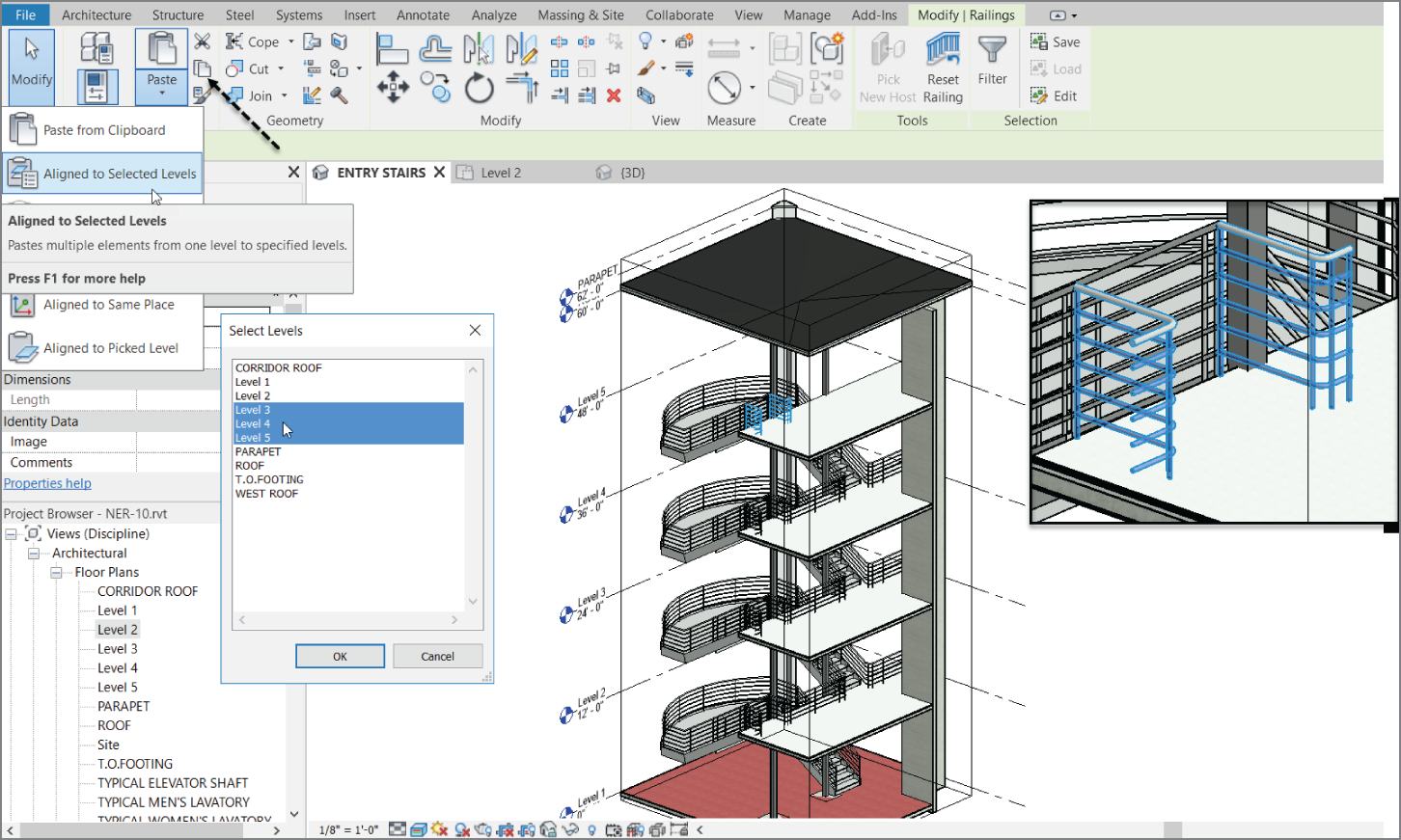
FIGURE 10.32 Using Paste ➣ Aligned To Selected Levels
- Go to Level 5.
- Select the little railing shown in Figure 10.33.
- Click Edit Path.
- Stretch the railing down to the wall, as shown in Figure 10.33.
Phew! You have built a set of stairs. The good thing is that it's one sweet staircase. The bad thing is that you used all the default layouts and materials. Next, we will get into some more complicated shapes and styles.

FIGURE 10.33 Stretching the railing within the Edit Path mode
Creating a Winding Staircase
Before you get started, you should know that you'll create this staircase by using the separate stair components. You can try to make a winding staircase by using the Run function, similar to the one you used earlier. But in many cases (especially when you run into an existing staircase in either a renovation project or an addition), you may need to draft the stairs and then model over the top of the drafting lines. What? Drafting in Revit? Of course. How else can you expect to get anything done?
The first thing you'll need to do is make modifications to the floor in a specific area to create a landing. Follow along:
- In the Project Browser, go to the Level 2 floor plan.
- Zoom in on the area between the corridor and the east wing, as shown in Figure 10.34.
- Select the Level 2 floor in the east wing (by floor, I mean select the actual floor we added to Level 2).
- Click the Edit Boundary button on the Mode panel of the Modify | Floors tab.
- Sketch a landing that is 8′–0″ (2400 mm) long 8'‐0” (2439 mm) wide. Center it on the reference plane, as shown in Figure 10.34.

FIGURE 10.34 Creating a landing. You'll add a door in a moment.
- Click Finish Edit Mode on the Mode panel. If you're asked if you want to attach the walls to the bottom of the floor, click Yes.
With the landing in place, you can now copy a door up to this level. To do this, you'll go to the first floor and copy the door that resides there. You can do this on your own, or you can follow along with these steps:
- In the Project Browser, go to the Level 1 floor plan.
- Select door 100B.
- Copy the door to the clipboard (click Copy To Clipboard on the Clipboard panel).
- Choose Paste ➣ Aligned To Selected Levels.
- Select Level 2, and click OK.
- In the Project Browser, go back to Level 2. The door and the landing are in place.
- Select the door and press the spacebar twice. This will flip the door into the hallway. We don't want to go knocking someone off our landing!
Next you'll create a winding set of stairs. The first task is to lay out the shape in the plan using simple drafting lines. The second task is to model over the lines you added by using various stair tools as follows:
- Select the Annotate tab.
- Click the Detail Line button, as shown in Figure 10.35.

FIGURE 10.35 Select Detail Line from the Annotate tab.
- On the Draw panel, click the Start‐End‐Radius Arc button, as shown in Figure 10.36.
- For the first point of the arc, pick the midpoint of the landing (see Figure 10.36).
- Move your cursor down, at 135° from the first point you just picked.
- Extend your cursor 11′–0″ (3300 mm), as shown in Figure 10.36, and then click to set the second point.
- To form the arc, move your cursor to the right until the radius snaps into place. When it does, pick the point as shown in Figure 10.37.
- Press Esc.
- On the Draw panel, click the Pick Lines icon.
- On the Options bar, add an increment of 1′–6″ (457 mm) to the Offset field (see Figure 10.38).
- Offset the center arc to the right and then to the left, forming a 3′–0″ (914 mm) overall winder, as shown in Figure 10.38.
- Press Esc.
- Click the Line tool, make sure Offset is set to 0, and then draw a straight line at each end of the arcs, as shown in Figure 10.39.

FIGURE 10.36 With the Start‐End‐Radius Arc button selected, start at the midpoint of the landing and then go southwest at an angle of 135° and a distance of 11′–0″ (3300 mm).
OK, take a breather. Compare the examples in the book to what you have. Are you close? If not, go back and investigate.

FIGURE 10.37 Picking the third point to form the arc. It will be tangent upon the first two points you picked.

FIGURE 10.38 Adding two more arcs based on the centerline of the first

FIGURE 10.39 Adding a straight line to mimic the first tread
The next step is to make an array of the straight lines you just added. These lines will wind up being the guidelines for your risers:
- Press Esc, and then select the line you just drew at the landing and the endpoints of the arcs, as shown in Figure 10.40.
- On the Modify tab, click the array button, as shown in Figure 10.40.
- Select Radial.
- For Number, type 21 (this will be the number of risers required to go from Level 1 to Level 2).
- Make sure Move To: 2nd is selected (see Figure 10.40).

FIGURE 10.40 Choosing the array options
- Click the Place button next to the Center Of Rotation option, as shown in Figure 10.41.
- Type SC (for snap center) and hover your pointer over the smaller arc. Once you see the center snap icon appear, pick the smaller arc.

FIGURE 10.41 Moving the center of rotation somewhere that makes sense
- Pick a point on the midpoint of the small line you drew (Point 1 in Figure 10.42).
- Move your cursor down until it gets to 7° (point 2 in Figure 10.42) and pick that point. You will create 21 lines all pivoting around your center point.
- Type TR (for Trim) and trim both arcs with the last line in the array, as shown in Figure 10.42.

FIGURE 10.42 The linework when complete
Now you can begin modeling the stairs. This procedure is nothing more than tracing the lines you've already added to the model. To do this, you'll use the available tools that you haven't touched in the previous staircase. (You can look ahead to Figure 10.43 for reference.) Follow along:
- On the Architecture tab, click the Stairs button.
- In the Properties dialog, change Base Level to Level 1.
- Change Top Level to Level 2.
- Click Edit Type.
- Click Duplicate.
- Call the stairs Corridor Entry Stairs.
- Click OK.
- In the Construction category, click the cell to the right of Run Type. It contains the text 2″ (50 mm) Tread 1″ (25 mm) Nosing 1/4″ (6 mm) Riser. When you click in the cell, you see a […] button. Click it.
- Choose Cherry for Tread Material.
- For Riser Material, do the same.
- Under the Treads category, select Front, Left And Right for the Apply Nosing Profile row.
- Click OK.
- Scroll down to the Supports category, and change Right Support from Stringer (Closed) to Carriage (Open).
- Click Carriage ‐ 2″ Width (50 mm) to the right of Right Support Type.
- Click the small […] button to the right of the cell.
- Change Material to Mahogany. Click OK.
- Change Left Support to Carriage (Open).
- Add Mahogany as the material to the Carriage ‐ 2″ Width. Your Properties dialog should look like the one shown in Figure 10.43.
- Click OK to get back to the model.

FIGURE 10.43 Customizing the stairs
It's time to add the stairs to the model. To do this, you'll first sketch the boundary:
- On the Modify | Create Stairs tab in Sketch mode, click the Create Sketch button, as shown in Figure 10.44.

FIGURE 10.44 Click the Create Sketch button.
- Make sure the Boundary icon is current. On the Draw panel, click the Pick Lines icon.
- Pick the two arcs defining the outside of the stairs. Notice the green arcs. This indicates that this is your boundary.
- On the Draw panel, click the Riser button.
- On the Draw panel, click the Pick Lines icon.
- Pick all of the lines you arrayed. This includes the bottom and the top lines (see Figure 10.45).
- Click the Stair Path button.
- Click the Pick Lines button.

FIGURE 10.45 Picking the detail lines to lay over the stair components
- Pick the centerline of the staircase. (It may not be visible, but when you click the Pick Lines button and hover over the center of the stairs, it will appear.)
- Click Finish Edit Mode on the Mode panel.
- Click the Railing button.
- Change the railing to Handrail ‐ Pipe, make sure the position is set to Treads, and click OK.
- Click the Finish Sketch button (the green check mark).
With the stairs roughed in, you need to get a better look at them. If you use the default 3D view, you need to turn off way too many items to see your stairs. Let's add a perspective view, just to see what's going on here!
If you're confident about adding your own perspective view, go ahead and put one in and name it EAST ENTRY FROM CORRIDOR. If not, follow along with these steps:
- In the Project Browser, go to the Level 1 floor plan.
- On the View tab, click the 3D View ➣ Camera button.
- Pick the first point shown in Figure 10.46.

FIGURE 10.46 Adding the perspective view
- Pick the second point shown in Figure 10.46.
- In the Project Browser, find the new perspective view, and rename it EAST ENTRY FROM CORRIDOR.
- In the perspective view, select Realistic. (It's located on the View Control bar at the bottom of the view.)
- Check out the view (see Figure 10.47).

FIGURE 10.47 Looking nice
The next series of steps involves mirroring the stairs to the other side of the landing. Then, of course, you need to add a landing railing so that people don't just walk out the door and off the ledge:
- Go to the Level 2 floor plan in the Project Browser.
- Select the stairs, as shown in Figure 10.48. You might have to move your cursor over the stairs so you don't accidently select one of the drafting lines.

FIGURE 10.48 Selecting the stairs
- On the Modify | Multi‐Select tab, click the Mirror ➣ Pick Mirror Axis button, as shown in Figure 10.49.
- Pick the center reference plane. (I told you this thing would come in handy.)
Your stairs are now mirrored to the other side of the landing (see Figure 10.49).
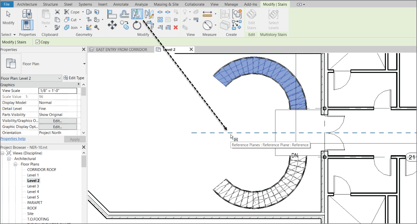
FIGURE 10.49 The mirrored stairs
Let's tie in the railings. If you're feeling up to the challenge, try it on your own by using the railing Handrail ‐ Pipe. If not, just follow along with these steps:
- On the Architecture tab, click the Railing button.
- In the Type Selector, change the type to Handrail ‐ Pipe, as shown in Figure 10.50.
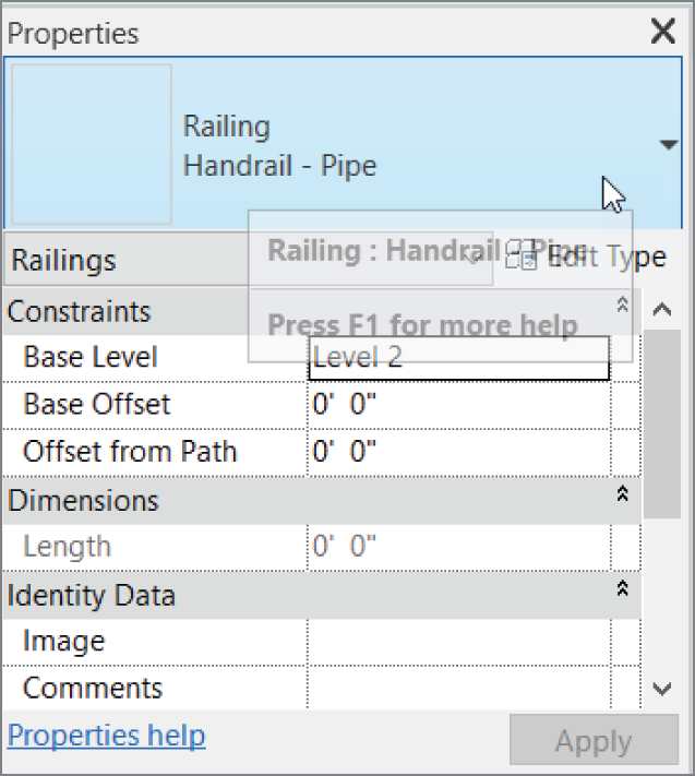
FIGURE 10.50 Setting the landing handrail type
- On the Draw panel, click the Pick Lines icon.
- Set Offset to 4″ (100 mm).
- Pick the landing lines to offset in the railing (see Figure 10.51).

FIGURE 10.51 The railing on the landing
- After the offsets are complete, click the Line icon on the Draw panel. Set Offset to 0.
- Draw the lines extending from the midpoint snap of the stair railing to the landing railing (see Figure 10.52).
- Trim the corners so your railings look like Figure 10.53.
- On the Mode panel, click Finish Edit Mode.
- You may have to flip the railing by selecting it and then clicking the Flip arrow.
- Add two more railings between the stairs and the brick wall. Your stairs should look like Figure 10.54.

FIGURE 10.52 Connecting the landing railing to the stair railing
Great! You're getting there. Now you'll see how a staircase and the accompanying railings come together. For example, it sure would be nice to have a railing with spindles or, better yet, panels added to it. Also, a nice half‐round bullnose would improve your staircase. The next section will focus on this concept.
Stair and Railing Families
Similar to the model as a whole, stairs and railings comprise separate families that come together to form the overall unit. Although stairs and railings are considered a system family (a family that resides only in the model), they still rely heavily on hosted families to create the entire element.

FIGURE 10.53 The completed landing

FIGURE 10.54 Check out the perspective view.
The next procedure will involve loading separate families into the model and then using them in a new set of stairs and railings that you'll create in the west wing:
- In the Project Browser, go to the Level 3 floor plan and change Detail Level to Fine.
- Zoom in on the west wing.
- On the Architecture tab, click the Floor button.
- In the Properties dialog, click the Edit Type button.
- Select the 4″ (152 mm) Concrete with 2″ (50 mm) Terrazzo floor system from the Type drop‐down list, as shown in Figure 10.55.
- Click OK.
- On the Draw panel, click the Pick Walls button.
- Pick the walls, and make sure the lines are set to the core centerline, as shown in Figure 10.55.
- When picking the south wall, select the Pick Lines button on the Draw panel, and set Offset to 5′–0″ (1500 mm) in the Options bar.

FIGURE 10.55 You must add a floor at the Level 3 floor plan for the stairs to have a landing.
- Once the sketch lines are in place, trim the corners and click Finish Edit Mode on the Mode panel.
- Revit asks if you want to attach the walls that go up to this floor's bottom. Click No.
- Revit asks if you want to cut the overlapping volume out of the walls. Click Yes.
Your floor is now in place. The next item you'll tackle is creating a completely custom railing system.
Creating a Custom Railing System
Next, you'll load the components that make up your stairs. Although Revit makes an attempt to supply you with some families, in this case you'll download the families included with this book by going to the book's web page at www.wiley.com/go/revit2020ner. From there, browse to the Chapter 10 folder and find the following files:
6210 (2‐5_8).rfalanding.rfapost.rfaraised panels.rfaspindle.rfastair nosing.rfa
To get started, you need to load the families into your model so that they're available when it comes time to assemble your new railing. If you remember how to do this, go ahead and load all the families that you just downloaded from the web page. If you need some assistance, follow these steps:
- On the Insert tab, click Load Family.
- Find the files that you downloaded from the web page.
- Select all of them, and click Open to load them.
- Save the model.
The next step is to create a new railing and add some of these items to it:
- In the Project Browser, find the Families category and expand it, as shown in Figure 10.56.
- Find the Railing category and expand it.
- Find Handrail ‐ Rectangular, and double‐click it (see Figure 10.56).
- Click Duplicate.
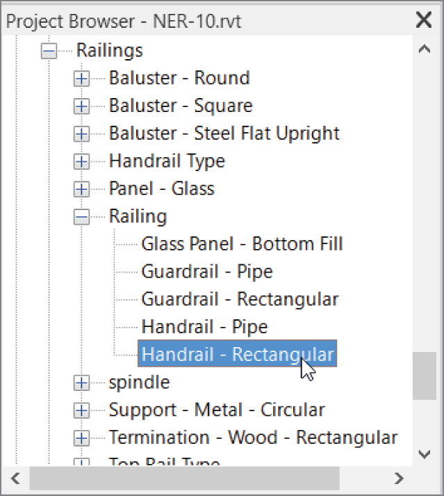
FIGURE 10.56 The railing family called Handrail ‐ Rectangular
- Call the new railing Wood Railing with Spindles.
- Click OK.
- Click OK again.
- In the Project Browser, under the Families category, scroll down until you see Top Rail Type, as shown in Figure 10.57.
- Double‐click the Circular ‐ 1 1/2″ (38 mm) Top Rail Type.
- Click Duplicate.
- Change the name to 6210, and click OK.
- Change Profile to 6210 (2‐5_8) : 2 5/8″ (67 mm).
- Change Transitions to Gooseneck.
- Change Material to Cherry, as shown in Figure 10.57.

FIGURE 10.57 Changing the rail. Note that you can add as many rails as you wish. Here, you're adding only one.
- Click OK.
- Under the Families category in the Project Browser, double‐click Wood Railing With Spindles, located in the Railing category.
- Scroll down to the Top Rail category.
- Click the browse […] button in the Type row (it currently has Rectangular – 2″ × 2″ [51 mm] selected).
- In the Type category, change the type to 6210 (see Figure 10.58).
- Click OK.

FIGURE 10.58 Adding the 6210 rail to the railing
- Click the Edit button in the Baluster Placement row.
- In the Main Pattern area, change Baluster Family to Spindle: 1″ (25 mm) (see Figure 10.59).
- Just below the Main Pattern area is the Use Baluster Per Tread On Stairs option. Select it, as shown in Figure 10.59.
- To the right is the Balusters Per Tread field. Specify two balusters per tread (see Figure 10.59).
- Change Baluster Family to Spindle: 1″ (25 mm), as shown in Figure 10.59.
- In the bottommost field is the Posts category. Change each of the three posts to None in the Baluster Family column. Your spindles are all you need (see Figure 10.59).

FIGURE 10.59 Adding the spindle to the Main Pattern area and specifying two balusters per tread and no actual posts
- Click OK.
- Click the ≪ Preview button at the bottom left of the dialog. This will give you a picture of the railing up to this point.
- Click OK again to exit the dialog.
You may or may not have noticed that you didn't get the opportunity to change the baluster's material as you did with the railing. This action must be done in the family itself, as follows:
- In the Project Browser, the Spindle category is just below Railing, as shown in Figure 10.60. Expand Spindle to expose the 1″ (25 mm) family.
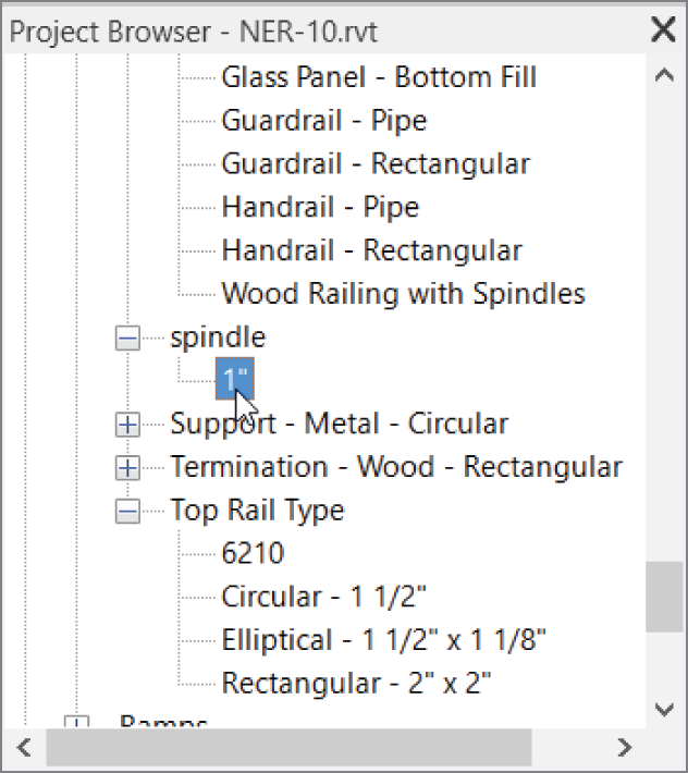
FIGURE 10.60 Finding the Spindle 1″ family to access the material
- Double‐click the 1″ (25 mm) family to open its Type Properties dialog.
- Find the Material row, click into the <By Category> field, and click the […] button.
- Change Material to Cherry.
- Click OK twice.
This completes the railing setup. Once you add it to the stairs, however, some tweaking will be required. The next step is to customize the stairs themselves.
Creating Custom Stairs
This is the third staircase you've created in the same chapter, so you've certainly gained some experience regarding the placement of stairs and railings into the Revit model. You're also becoming familiar with the stair and railings dialogs. This last procedure will tie all of that together.
Let's create that staircase:
- On the Architecture tab, click the Stairs button.
- In the Properties dialog, make sure you choose Cast‐In‐Place Stair Monolithic Stair, as shown in Figure 10.61, and click the Edit Type button.
- Click Duplicate.
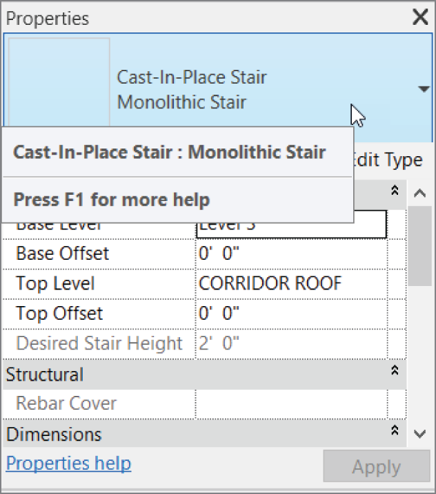
FIGURE 10.61 Configuring the stairs. As you can see, you have quite a few options.
- Call the new staircase Custom Bullnose Stairs.
- Click OK.
- Under Construction, next to Run Type ¾″ Nosing Profile, click into the Default cell and change Default to stair nosing:.
- Apply the nosing profile to Front, Left, and Right.
- Select the Riser check box.
- Change the riser thickness to 3/4″ (19 mm).
- For Riser To Tread Connection, choose Extend Tread Under Riser.
- Change Monolithic Material to Mahogany.
- Under Treads, make sure Treads is selected.
- Change Tread Material to Mahogany.
- Change Riser Material to Mahogany.
- Click OK.
- Click the 7″ (178 mm) Thickness cell next to Landing Type, and click the […] button to the right.
- Click Duplicate.
- Call the new landing 1′–0″ (300 mm) Mahogany Landing.
- Change Monolithic Thickness to 1′–0″ (300 mm).
- Change Monolithic Material to Mahogany.
- Click OK twice.
It's time to configure some of the layout properties. These will allow you to calculate the rise/run count as well as some basic offsets you'll need:
- In the Properties dialog, set Base Level to Level 1.
- Set Base Offset to 6′ 5/8″ (152 mm), as shown in Figure 10.62.
- Set Top Level to Level 3. (Yes, this is going to be one long staircase!)

FIGURE 10.62 The Base Offset value is set to 6′ 5/8″ (152 mm).
The next step is to place this monster into the model. Given the fact it is spanning 24′ (7315 mm), you'll need multiple landings to give your visitors a breather as they travel up the stairs. This layout will require a little more care in the initial planning stage:
- On the Work Plane panel, click the Ref Plane button.
- Click the Pick Lines button, and then create a layout, as shown in Figure 10.63. (It will make sense, I promise)!

FIGURE 10.63 Using dimensions to lay out the centerlines of the stairs
- Click the Railing button.
- Change the railing type to Wood Railing With Spindles, and make sure Position is set to Treads. Click OK.
- On the Modify | Create Stairs tab in Sketch mode, click the Run button.
- For the Location Line, select Run: Center.
- Draw your stairs as shown in Figure 10.64 up to point 6. (Pick the points in the figure as sequenced.)
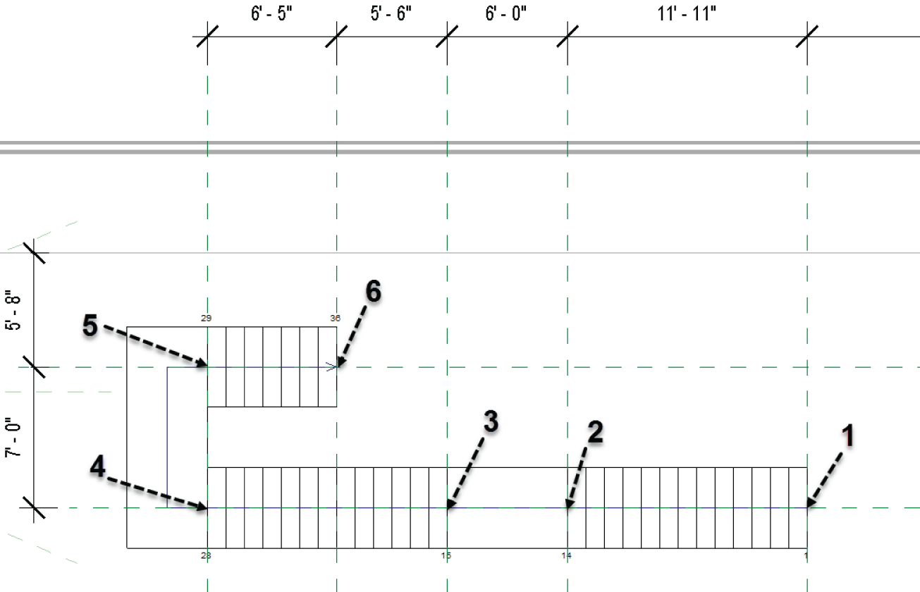
FIGURE 10.64 Picking the intersections of the reference planes to determine where the stairs will go
- For the next point, align your cursor with the upper stair stringer and pick the intersection labeled 7.
- Now pick point 8 (see Figure 10.65).
- Click Finish Sketch. Your stairs should look like Figure 10.65.

FIGURE 10.65 Point 7 is aligned to the top of the stairs.
- Go to a 3D view to check out the stairs. (Remember, you can select the stairs and click the Section Box button on the View panel.) Your stairs should resemble Figure 10.66.

FIGURE 10.66 The finished stairs
The next step (pun intended) is to add a landing to the bottom of the stairs. This requires creating a family. Be sure you have downloaded the families included with this chapter.
Adding a Custom Landing
You left the 6′ 5/8″ (152 mm) offset for the bottom tread because you need to introduce your own version of how that bottom tread should look. If you haven't already loaded the family, go to www.wiley.com/go/revit2020ner. From there, browse to the Chapter 10 folder and find the Landing.rfa and Post.rfa files. After you've loaded the families, proceed with these steps:
- In the Project Browser, go to the Level 1 floor plan.
- On the Architecture tab, click the Component button.
- In the Type Selector, find and select the Landing family.
- As you are inserting the family, press the spacebar three times to rotate the landing into the correct orientation.
- Place the landing under the last tread at the point shown in Figure 10.67.

FIGURE 10.67 Placing the landing
- Press Esc twice.
- Select the landing.
- In the Properties dialog, change Tread Material to Cherry.
- Change Base Material to Mahogany, and click OK.
- Scroll down and change the Length to 6′‐0″ (1829 mm). See Figure 10.68.
The next task is to add a post.

FIGURE 10.68 Changing the landing material and width to match the theme of the staircase
Adding a Gooseneck
In this style of railing system, it would be nice to have a gooseneck to catch the railing as it slopes downward and spiral it into the post. Of course, Revit doesn't have families for this built in, but this book does! If you didn't download the post family earlier in this chapter, go to the book's web page, browse to the Chapter 10 folder, and find the Post_up.rfa file. After you download it and load it into the model, follow these steps:
- In the Project Browser, go to the Level 1 floor plan, and zoom in on the landing area, as shown in Figure 10.69.
- On the Architecture tab, click the Component button.
- In the Properties dialog, select Post_up: with Gooseneck.
- Place it on the landing slightly away from the stair railing.
- Select the post, and change Offset From Host to 6 5/8″ (152 mm) in the Properties dialog.

FIGURE 10.69 Placing the post with the gooseneck
- Select the post again (if it's not still selected).
- Click the Move button.
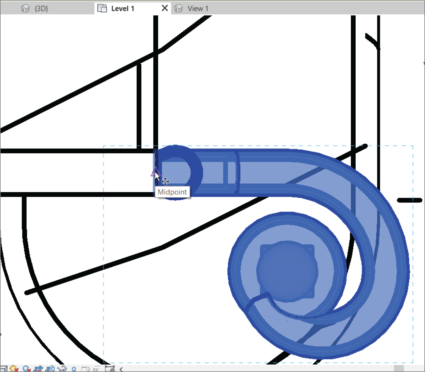
FIGURE 10.70 Moving the post to align with the stair railing
- Move the post from the midpoint of the post's end to the midpoint of the stair railing's end, as shown in Figure 10.70.
- Select the post again (if it's not selected already).
- In the Properties dialog, click Edit Type button, go to the Materials And Finishes category, and change materials for both the rail and the post to Cherry.
- Mirror the post to the other railing.
In 3D, your landing should now look like Figure 10.71.

FIGURE 10.71 The completed landing
Adding a Railing to the Landing
Let's add the railing to the Level 3 balcony. Compared to that landing you just did, this is going to be a snap! If you feel as though you have the experience required to add your own landing railing, go ahead and take a shot at it. If not, follow these steps:
- In the Project Browser, go to Level 3.
- Zoom in on the stairs.
- Right‐click one of the railings on the stairs, and click Create Similar.
- Sketch a railing that is 4″ (100 mm) in from the face of the landing, as shown in Figure 10.72.
- Make sure you have a “leg” tied into the stair railing.
- On the Railing panel, click Finish Edit Mode.
- Repeat the procedure on the other end (see Figure 10.73).

FIGURE 10.72 Adding the railing. This process is becoming old hat!

FIGURE 10.73 Both railings are in place.
OK, so we just looked at three different ways to model stairs. Up to this point we have dealt with railings, but we have not considered how we can make custom adjustments to the top rail. The objective of this next series of steps is to add a bottom extension to the railing in our entry area.
- Go to Level 1 and zoom in on the east part of the east building.
- Select the section that we added called SECTION AT STAIRS. (You need to select the line of the section, not the bubble.)
- Now you will see what is called a flip grip. Click the flip grip as shown in Figure 10.74 to flip the section in the opposite direction.

FIGURE 10.74 Flip the section so it is facing down.
- Double‐click the section bubble to open the view.
- Hover over the top rail on the railing going down the stairs.
- Press Tab until only the top rail is highlighted. Once it is, select it.
- Click the Edit Rail icon, as illustrated in Figure 10.75.
- Zoom into the bottom of the rail and click the Edit Path button, as shown in Figure 10.76.

FIGURE 10.75 You can edit the top rail independent of the rest of the railing system.
- Draw a diagonal line 1′‐0″ (305 mm), as shown in Figure 10.77. Notice that it will align with the slope of the railing.
- Complete the rail extension as shown in Figure 10.77.
- Click the Edit Rail Joins icon.
- Pick the upper intersection, as shown in Figure 10.78.
- Select Fillet from the menu.
- Add 3″ (76 mm) to the Radius field.
- Click the green Finish Edit Mode icon.

FIGURE 10.76 Click Edit Path.

FIGURE 10.77 Adding a custom rail extension
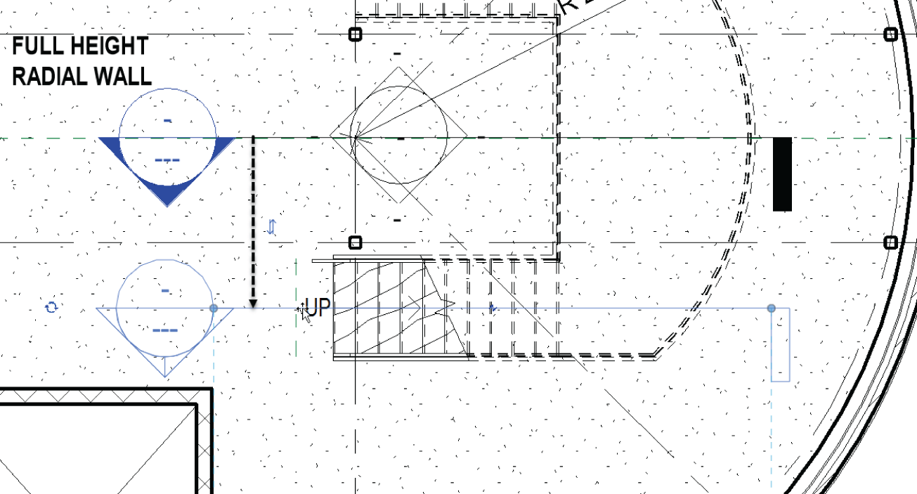
FIGURE 10.78 Adding a custom rail extension
- Go back to Level 1 and move the section down so that it cuts through the stairs, as shown in Figure 10.79.
- Open the section and edit the top rail following steps 9–14. You can do it!

FIGURE 10.79 The finished railing
The last section of this chapter focuses on adding ramps to the model. As far as Revit procedures go, ramps are the kid sister to stairs.
Adding Ramps
When you think of a ramp in Revit, think of a one‐tread, one‐rise staircase at a 1/12 pitch. A ramp is placed in the model exactly the same way as a set of stairs. You still have the run method, and you can still sketch the ramp by using a boundary.
That being said, let's start placing a ramp in your model:
- In the Project Browser, go to the Level 1 floor plan.
- Zoom in on the radial entry of the east wing at grid intersection F‐7 (see Figure 10.80).
- You need to create a flat landing, so, on the Architecture tab, click the Floor button.
- Click Edit Type in the Properties dialog.
- Select Generic ‐ 12″ (305 mm) Filled.
- Click Duplicate.
- Call the new floor Exterior Concrete Slab.
- Click OK.
- Click the Edit button in the Structure row.
- Change Structure [1] Material to Concrete ‐ Cast‐In‐Place gray.
- Change Thickness to 6″ (150 mm).
- Click OK twice to get back to the model.
- Place the concrete at the points shown in Figure 10.80.
- When the slab is in place, click the Finish Edit Mode button.
- Click No if you get a prompt asking if you want to attach the walls to the bottom of the floor.

FIGURE 10.80 Sketching the slab perimeter
Now you can add the ramp. You'll set the ramp's properties for the top to Level 1, and the bottom will also be at Level 1 but with an offset:
- On the Architecture tab, click the Ramp button, as shown in Figure 10.81.

FIGURE 10.81 The Ramp button
- In the Properties dialog, click Edit Type.
- Click Duplicate.
- Call the new ramp Exterior Concrete Ramp.
- Click OK.
- Give it a 6″ (150 mm) thickness.
- Change Function to Exterior.
- For the ramp material, click the […] button, and specify Concrete ‐ Cast‐In‐Place Gray, as shown in Figure 10.82.

FIGURE 10.82 Modifying the type properties
- Notice that Maximum Incline Length is set to the ADA standard of 30′–0″ (10000 mm).
- In the Other category, notice that Ramp Max Slope is set to 1/12.
- Click OK.
- In the Properties dialog, set Base Level to Level 1.
- Set Base Offset to ‐2′–6″ (‐750 mm), as shown in Figure 10.83.
- Set Top Level to Level 1.
- Set Width to 5′–0″ (1500 mm) (see Figure 10.83).

FIGURE 10.83 Setting the instance properties
- On the Draw panel, click the Run button.
- In the model, click the first point for the ramp, similar to the point shown in Figure 10.84. (You have to place the point near the midpoint. Revit does not allow you to snap while in Sketch mode for some annoying reason.)
- Move your cursor down the view (south) 15′–0″ (4500 mm), as shown in Figure 10.84. (You'll see the temporary dimension.)

FIGURE 10.84 Pick the first point on the landing, and then move your cursor down 15′–0″ (4500 mm).
- Pick a point about 6′–0″ (1800 mm) below the end of the ramp, in alignment with the right boundary, as shown in Figure 10.85.
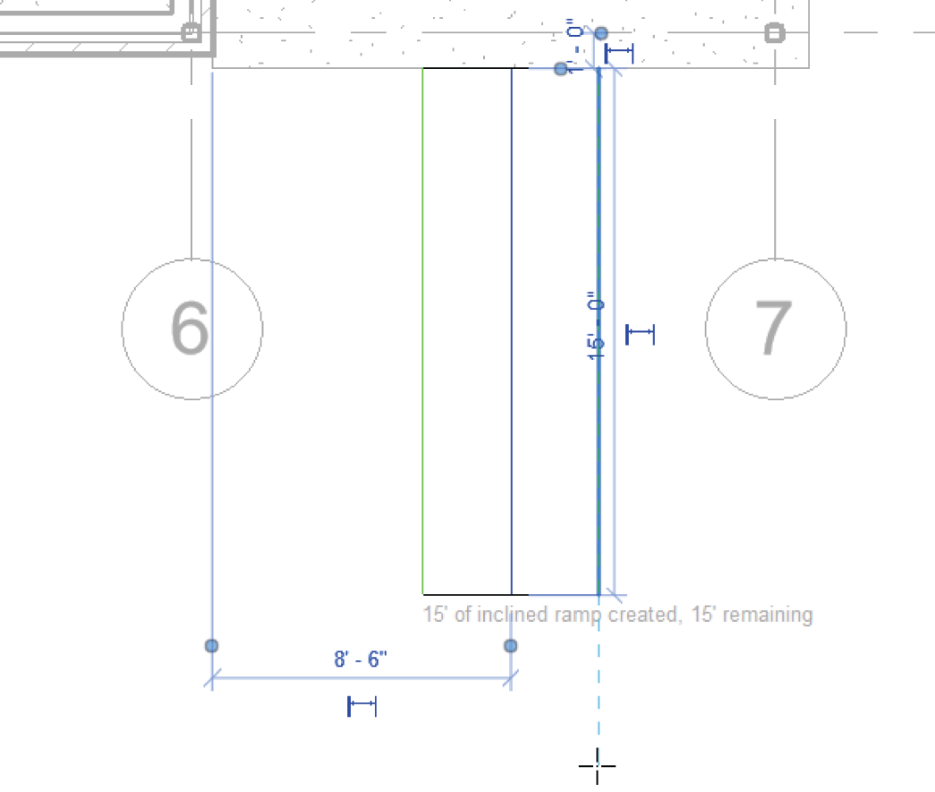
FIGURE 10.85 Pick a point to start the second leg of the ramp and to create the landing.
- Move your cursor to the right until the ramp stops (see Figure 10.86).

FIGURE 10.86 Pick the last point on the ramp.
- On the Modify | Create Ramp tab in Sketch mode, click the Railing Type button.
- Select Handrail ‐ Pipe in the Railing Type dialog that opens.
- Click OK.
- Click Finish Edit Mode.
- Select the entire ramp (including the railing).
- Move the ramp so that the midpoint of the top of the ramp meets the midpoint of the landing slab.
You may notice immediately that the ramp is sloping in the wrong direction. Also, you need to tie the railings into the slab. If you would like to pick around and see how to do these things on your own, go right ahead. Otherwise, follow along:
- Select the ramp.
- Pick the small blue arrow—this flips the direction of the ramp.
- On the Architecture tab, click the Railing button.
- In the Properties dialog, click Edit Type, change the type to Handrail ‐ Pipe, and click OK.
- Draw a railing 6″ (152 mm) in from the slab edge, as shown in Figure 10.87.

FIGURE 10.87 Adding the railing just as you've been doing this entire chapter
- Mirror the slab, the ramp, and the railing to the other side of the building, as shown in Figure 10.88. If it gives you a warning that floors overlap, you can ignore it. They really do not.
- Save the model.
Creating ramps is necessary in almost every project. Some will be easier than others, and at times, they may try your patience. Keep at it, and before long you'll have the experience you need to feel confident in creating ramps.

FIGURE 10.88 The two ramps
Are You Experienced?
Now you can…
- create stairs with the conventional method by using the Run command to generate the height and length you need
- create stairs by first laying out the geometry by placing linework in the model and then tracing over the lines with the stair components
- determine the difference between the boundary and the riser when you need to sketch the stair profile
- load necessary components used to customize stairs and railings such as railing types, spindles, posts, and landings
- use separate components and access them in the Project Browser to place materials
- configure railings based on the baluster placement and the railing placement as used in the element properties of the railing
- determine how to tie a railing into a stair railing by using offsets and by aligning the railing sketch with the stairs
- add a line‐based, raised‐panel family to complete millwork items
- create ramp landings and create the actual ramp
- determine the length of the ramp based on the rise and run of the slope