Note: I did not actually follow these steps in the order presented. I did a lot of trial fitting, testing, etc., before I arrived at the final assembly. But if I had it to do all over again, this is the way I would do it.
1. Prepare the enclosure. Fitting the PID into the project box was a bit tricky for someone of my limited craftsmanship. The screw towers and circuit board holders in the enclosure interfered with the placement of the PID. I ended up cutting a slot through one end of the enclosure with a hand miter saw and a coping saw. The distance between the circuit board holders molded into the enclosure is very close to the height of the PID, so I simply cut down along the circuit board holders, broke out the piece of plastic between the cuts with a pair of pliers, and reamed out the opening with a power drill until the PID fit.
I also drilled a ¼″ hole in the back of the enclosure to run wires to the PID and a ¾″ hole in the top towards the back to mount the (entirely superfluous) lighted rocker switch. Actually mounting the PID in the enclosure is simple enough once the opening is prepared: slip the white mounting collar over the PID, slide the PID into the enclosure, then cinch the mounting collar up tight against the inside of the enclosure. This is easier to do than it is to describe.
2. Open Silvia. (Unplug it first!) Silvia is a breeze to open — especially compared to my first machine, a DeLonghi, which was held together by hidden tamper-proof screws.
2a. Remove the water reservoir. Shake the excess water out of the two water hoses into a towel or sink.
2b. Remove the four screws that hold on Silvia’s top. Set the top aside.
2c. Remove the two screws that hold on the front splash panel. Set the splash panel aside.
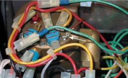
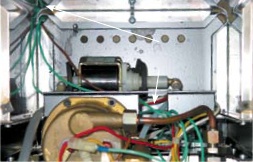
3. Install the thermocouple. Now that Silvia’s innards are exposed, you can see the bronze-colored boiler with many wires and two blue cylinders attached to it. The blue cylinders are the thermostats. The thermostats are attached to the boiler by three screws. Remove one of the screws, slip the washer end of the thermocouple under the “ear” of the thermostat, and then replace the screw through the thermostat and the thermocouple washer (see Figure 4-1). I test-mounted the thermocouple under the leftmost screw, but later moved it over to the rightmost screw, which is closer to where the cold water enters the boiler. I’m not sure it makes any difference in operation.
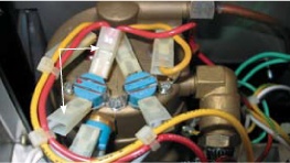
4. Remove wires from brew thermostat. The brew thermostat is the blue cylinder on the left. Unplug both connectors from the thermostat (see Figure 4-2).
5. Attach heater circuit wires to the solid-state relay (SSR).
5a. Cut two pieces of wire about 12″ long. Strip the ends of both wires.
5b. Crimp a connector onto one end of each wire.
5c. Plug the connectors into the wires detached from the thermostat in step 4 (see Figure 4-3).
5d. Run the other ends of the wires through Silvia’s chassis so that they protrude down behind the splash-guard.
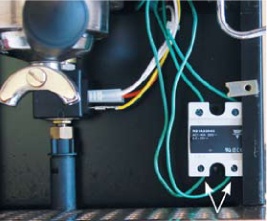
5e. Attach the bare wire ends to the SSR. There are four terminals on the SSR; on mine, they were labeled L1, T1, A2(+), and A2(-). Attach the wires to L1 and T1. It does not matter which wire goes to L1 or which to T1. My SSR has screw/clamp terminals; simply slide the wire into the terminal and tighten the screw to hold it in place. If necessary, trim the wires before attaching to the SSR so there is not an excess of wire behind the splashguard (see Figure 4-3).
6. Attach the PID control wires to the SSR.
6a. Cut two more pieces of wire, about 36″ each. They need to be this long because I decided to run the wires out to the PID. Strip the ends.
6b. Since all of the wire I used was the same color, I marked both ends of one piece with tape so I could identify it later.
6c. Run one end of each wire from the boiler compartment down to the SSR.
6d. Attach the wire marked with tape to the ‘+’ terminal on the SSR. Attach the other wire to the ‘-’ terminal (see Figure 4-4).
7. Run control wires and thermocouple wire out to the PID. I did not want to cut a hole for the wires in Silvia, so I decided to run them out of an existing gap in the bottom left corner at the back of Silvia.
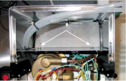
7a. Remove the panel that fits between the water reservoir and the boiler compartment. It is held on with two small machine screws and lock washers on the water reservoir side. The panel is angled and may need a bit of fiddling to get it to slide out (see Figure 4-5).
7b. Run the cycle time (TC) and control wires (the ones attached to the + and - terminals of the SSR) out of the boiler compartment, along the bottom of the water reservoir compartment, and out the opening in the bottom corner of the water reservoir compartment (see Figure 4-6).
7c. Reinstall the panel removed in step 7a.
8. Wire the PID.
8a. Cut the receptacle end (not the end that plugs into the wall) off of the extension cord and strip the ends of the wires about ¼″.
8b. Run the extension cord, TC wire, and SSR control wires through the hole drilled in the back of the enclosure.
8c. Slide the white mounting collar over the back of the PID (it must go on before the wires are attached, for obvious reasons).
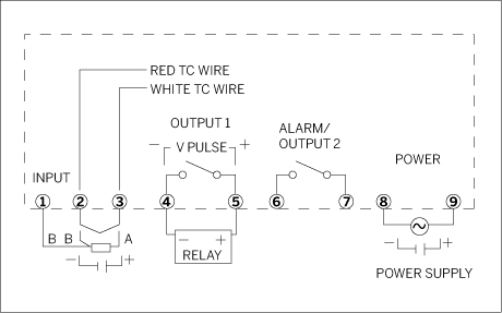
8d. Attach the wires to the PID as follows (see Figure 4-7). The PID has simple screw clamp terminals, so just slide the wire into the appropriate terminal and tighten the screw.
8e. The ends of the thermocouple wire go to terminals 2 (red wire) and 3 (white wire). The first time I wired up my PID, I had the leads reversed. When the PID turned on the heating element, the temperature readout started to drop instead of rise.
8f. The ends of the SSR control wires go into terminals 4 and 5. Be sure to match the + wire from the SSR to the + terminal on the PID, and the - wire to the - terminal. That’s why I marked the wire with tape in step 6b.
8g. The ends of your power cord go into terminals 8 and 9. (Note: The lighted rocker switch, if used, gets wired between the power source and the PID. I left that step out because the switch is totally superfluous.)
8h. Terminals 1, 6, and 7 are unused.
9. Mount the PID in the enclosure. Slide the PID into the enclosure. Cinch the mounting collar snug against the inside of the enclosure. Screw the cover onto the enclosure. I attached the enclosure to Silvia with double-sided foam tape. Not the most elegant solution, I guess, but it is cheap, fast, simple, and reversible.
10. Secure the SSR, and reinstall the splash panel. Behind Silvia’s front splash panel is a bolt that can be used to secure the SSR. I did not have a 4mm washer and nut (available at your local hardware store) to use for this purpose, so I simply hung the SSR on the screw, and then put the splash panel back in place.
11. Reinstall Silvia’s top and water reservoir. Put the top back on, tighten up the four screws that hold it down, and reinstall and refill the water reservoir.
12. Fire up! Plug Silvia in, plug the PID in, and turn Silvia on. The PID should display the boiler temperature after a second or two. Press the SEL button on the PID to see the setpoint temperature; use the up and down arrow buttons to adjust the setpoint to 230° F.
