This chapter provides a broad overview of electronics to readers who have little to no experience with electronics and electricity. If you’re already comfortable with some of the topics in this chapter, you can treat it like a choose your own adventure book and skip to subjects you want to learn more about or even move directly on to Project 1.
If you’re new to electronics or just want a refresher, we suggest reading this chapter in full. While it’s not a complete guide to electronics (there are whole books, classes, and degrees on the subject), this chapter is a handy reference designed to arm you with basic concepts and vocabulary. If you’re looking for more in-depth information on electricity, electronics, and circuits, please see the recommended reading list at the end of this chapter.
Electricity is an odd beast. In a lot of ways it’s predictable, but it can be a little sneaky at times. If you look up electricity in the dictionary, you’ll probably find the definition sheds little light on what it is, how it works, or, most importantly, how you can use it. Let’s start with the basics.
To understand electricity, you first need to understand the structure of an atom. Atoms are the building blocks of everything around you. An atom is made up of protons, neutrons, and electrons. The electrons have a negative charge, and the protons have a positive charge. A typical atom has the same number of electrons as protons and therefore is neutral in charge. Electricity is a form of energy that involves the movement or storage of charges; it is the phenomenon that occurs when we push or force charges to move in a prescribed manner or a defined path. If you’ve ever seen a lightning storm, you’ve seen evidence of the transfer of charges between the clouds and the ground. These charges are transferred through the air molecules of our atmosphere, lighting up the sky as they move. The movement and transfer of charges is called current. Current is measured in units called amperes (A) or milliamperes (mA).
NOTE
Conventionally, we refer to current as the movement of a positive charge. Though technically the electron is the part of the atom that can be moved, it is still common to refer to current as the movement from positive to negative.
Except for lightning, arc welding, and the odd static shock, we don’t normally see electricity directly. Even the bright light we see in lightning is merely the air molecules changing form as charges move through them.
Charges move when there is an electrical force that acts on them and a path for the charges to move along. That electrical force is created by an electrical potential difference, or what we commonly call voltage. Voltage is what ultimately causes charges to move, and it’s measured in volts (V). For a reference, typical batteries range in voltage from about 1.5 V to 12 V. A 12 V battery will cause charges to move faster than a 1.5 V battery.
In general, electricity can be broken down into two basic types: direct current (DC) and alternating current (AC). AC is the kind of electricity in the power lines outside your house and in your wall outlets. AC electricity is great for power generation (for example, power plants), transmitting power over long distances (like from the power plant to your home), and driving large devices (like motors and heaters). We don’t use AC electricity for most of our household electronics, however. Most small appliances and household electronics that plug into the wall outlet require DC electricity and use a transformer to convert from AC to DC. Further details on AC and DC are beyond the scope of this book, but the projects you build here will focus on DC electricity.
Even with the electrical forces pushing them, charges need a path to follow from a point of higher potential to a point of lower potential. The path by which charges move from the positive (+) side of a battery (high potential) to the negative (–) side of the battery (low potential) is called a circuit. A circuit consists of a closed path from the positive terminal to the negative terminal through a device such as a light-emitting diode (LED), resistor, light, or motor. Figure 1 shows a simple circuit containing an LED, a battery, and a resistor. Notice that the shape of the circuit loosely resembles a loop or a circle, hence the name circuit.
In order for charges to move, the path must be made out of a material that is conductive. Conductivity is not an absolute measure but more of a continuum. While some materials are generally considered conductors and nonconductors, most materials occupy a range of values for conductivity. In other words, some materials allow charges to move more freely than others. Think of driving a car on different surfaces. On the smoothly paved interstate, you can go much faster than if you were off-roading or driving down dirt roads. Different roads allow for different speeds the same way that different materials allow for more or less conductivity. We use the term resistance to describe how much a material slows down the movement of charges.
As you may already have guessed, there is a relationship between current, voltage, and resistance. This relationship is commonly called Ohm’s Law, and it is represented mathematically as follows:
V = I × R
In this equation, V represents the voltage, I represents the current, and R is the resistance. (Don’t let this bit of math scare you: this is one of only about three equations you’ll see in this book.)
To understand what’s going on in a circuit, it’s useful to think of electricity like water moving through pipes. Imagine water flowing through a garden hose. When you turn on the valve, water starts to flow through the hose to the other end, as shown in Figure 2.
FIGURE 2: Water and electricity model
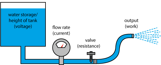
The water molecules moving in the hose represent the flow of charges (current). If we turn the water valve up or down, we can change the water pressure in the hose. The water pressure in the hose is similar to the voltage in a circuit. If you increase the water pressure, the flow also increases. This is the same with circuits: if you increase the voltage, the current also increases. The final part of the analogy is in the hose itself. If we put a kink in the hose or restrict its diameter, we create resistance. The increase in resistance slows down the flow (lowers the current).
This model works pretty well to describe the flow of electricity, but you don’t want to set up this whole system of hoses, valves, and pipes to just let water run out onto the ground (unless your goal is to water the lawn). You want to do something with it; you want it to do work. In terms of circuits, we use devices that change electricity into other forms of useful energy, such as illuminating a light, rotating a motor, or sounding a buzzer. A device that converts electrical energy to other forms of energy is called a load. Thomas Edison discovered that he could convert electrical energy into light energy with the light bulb; you will do that and a whole lot more throughout this book.
While pictures are nice, it’s not efficient to meticulously draw out every component to show how a circuit is wired up. Throughout the book, you will see schematics like the one in Figure 3 as well as illustrations to help you with your circuits.
FIGURE 3: This simple schematic shows a battery, an LED, and a resistor.
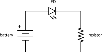
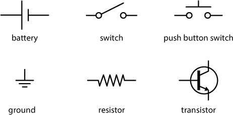
Schematics are simplified drawings of circuits. We sometimes also call these wiring diagrams or circuit blueprints. A schematic shows what is connected to what and which components to use in building the circuit. We will use the IEEE (Institute of Electrical and Electronics Engineers) US standard for drawing circuits in this book. The schematic in Figure 3 actually represents the same circuit as the illustration in Figure 1. The straight lines represent wires, and each component has its own unique symbol. Figure 4 shows some common schematic symbols you’ll see in this book.
FIGURE 4: Some standard IEEE schematic symbols
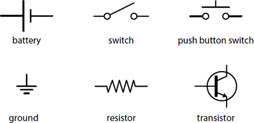
The IEEE schematic symbol format is internationally recognized and used to communicate and share circuit drawings across the world. It’s intended to quickly represent components using very simple lines and drawings.
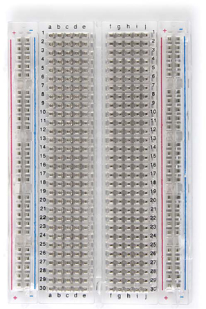
As you work through the projects in this book, you will build and test a variety of designs. As you build a circuit, you may also want to rearrange parts, swap things around, or add new components. This process is called prototyping. You can prototype electronics in a way that is similar to building with wooden blocks or LEGO bricks by using a solderless breadboard like the one shown in Figure 5.
FIGURE 5: A translucent solderless breadboard with horizontal rows and vertical power rails
A solderless breadboard is a plastic rectangle with a lot of holes in it. These holes are spaced on a 0.100-inch grid and sized so that the majority of electronic components fit snugly in them. Underneath the holes are small clips made out of a soft conductive metal, as shown in Figure 6.
FIGURE 6: The innards of a solderless breadboard (left) and a close-up of the metal clip inside (right)
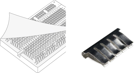
Wires that are plugged into holes on the same row are connected together electrically by these metal clips. It’s like twisting the wires together without the twisting part. Notice that the clips only span the width of five holes. There is a center “ditch” that divides the two halves of the breadboard, and the clips on the right side are not connected to the clips on the left side.
NOTE
Hold the breadboard so that it is tall and skinny (portrait orientation) and the letters at the top are right side up. We’ll refer to the horizontal groupings of five holes as rows and the vertical sections on the sides of the breadboard as columns, assuming this orientation.
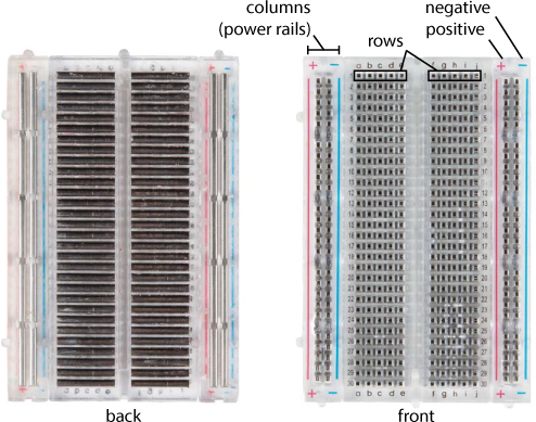
Breadboards come in a number of shapes and sizes, but most will still have vertical columns on the outer edges of the board. These columns are called power rails or power buses, and each has a single continuous clip that is connected from top to bottom, as in Figure 7. Breadboards also often have + and – labels to indicate where to plug in your power connection, with matching red and blue color coding.
FIGURE 7: Underside of a breadboard, showing both horizontal rows and vertical power rails
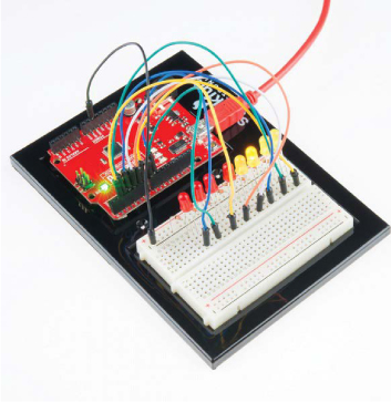
You can see a solderless breadboard in action in Figure 8, which shows a prototype design of a circuit with eight LEDs.
FIGURE 8: Circuit on a breadboard
In this book, you’ll build circuits with solderless breadboards so that if you make a mistake, you can easily change or fix it, and if you want to explore something further, you can quickly add to the circuit. When you start making bigger and more complex circuits, we suggest that you have multiple breadboards around so that you can build circuits in chunks. This allows you to build and test each part of your project incrementally without having to rework, troubleshoot, or take an entire project apart when something doesn’t work.
We mentioned components earlier and want to touch on them briefly here. There are hundreds, if not thousands, of different electrical components in the world. When we say components, we are talking about discrete components—the most rudimentary parts you can buy. For example, the resistor, capacitor, and LED in Figure 9 are discrete components.
On the other hand, a breakout board is an assembly of components prewired together onto a single board made to be breadboard friendly. Breakout boards help speed up the prototyping process. You can see a good example of one in Figure 10.
FIGURE 9: Resistors (left), capacitors (center), and LEDs (right) are examples of discrete components.
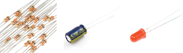
FIGURE 10: A single, tiny accelerometer (left) and its breakout board (right). Notice the plated-through holes on the left side of the breakout board.
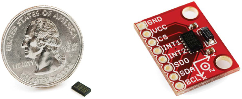
Figure 10 compares a complex component—an integrated accelerometer sensor package (P/N ADXL345 from Analog Devices)—and the breakout board SparkFun produces for it. The chip measures a mere 5 × 3 mm! It has tiny metal connection pins that serve a similar purpose to the long metal legs you see on discrete components. They’re just so small that connecting wires directly to them is nearly impossible. Breakout boards route these small connection points to plated-through holes on the edge of the board, spaced exactly 0.100 inch apart so that the holes on the board line up with the holes on a solderless breadboard. Each hole is metal plated so that you can solder wires directly to it. Or, if you want to use it with a breadboard, you can also solder on male headers as shown in Figure 11. (Don’t worry if you’ve never soldered before; see the instructions in “How to Solder” on page 302.)
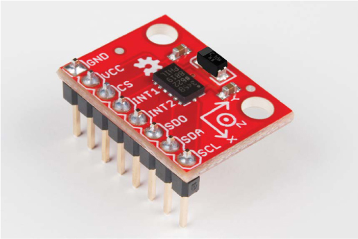
Notice that the holes are each labeled with a silkscreen so you know how to connect the sensor. Breakout boards have these so you can use them immediately on a breadboard without the hours of researching and building you’d have to do to use the bare component on its own.
FIGURE 11: ADXL345 breakout board with headers
With the concepts of circuits, components, voltage, current, and resistance defined, we can now talk about two different approaches to electronics: analog and digital. These approaches are not mutually exclusive, and you can’t really understand the circuits you build without understanding both concepts.
Analog deals with values that vary within a set range. Think of the dimmer switch in some dining rooms; that is analog. Analog values can be on, off, and anything in between. Digital values, on the other hand, have only two states: on or off.
Digital electronics tend to include a microcontroller or microprocessor that is programmed to turn things on and off in response to conditions, whereas analog circuits tend to use components to vary the current, voltage, and resistance of a circuit to achieve the same result.
There are advantages and disadvantages to both ways of thinking, but you can’t solely use one and not the other. For example, you couldn’t read the temperature using a microcontroller without using a number of analog components as well.
A microcontroller is a small computer that you can program by uploading a program or set of instructions. Microcontrollers are used to automate simple tasks, like controlling the temperature of your house or watering your lawn when it’s dry.
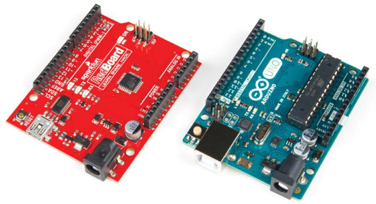
The projects in this book use the SparkFun RedBoard microcontroller board, which is 100% compatible with the Arduino Uno. Both are pictured in Figure 12.
FIGURE 12: The SparkFun RedBoard (left) and the Arduino Uno (right) microcontroller boards
In an average day, you probably use 15 to 20 microcontrollers and you don’t even know it. They are in your coffee maker, alarm clock, and microwave. Your car alone has anywhere from 5 to 10 of them that control the braking, stereo, and ignition systems. Our world practically runs on microcontrollers. This book will help you learn how to harness that fact to take back a bit of control over your world.
NOTE
You will learn more about the Arduino, how to program it, and what its capabilities are as you build the projects. For now, just know that a microcontroller is a programmable brain that makes electronics easier for anyone to build and prototype ideas that automate the world around them.
We hope that this short primer has given you a little background and a preview of what the rest of this book will cover. We’re excited that you’ve decided to embark on this adventure with us. Now, let’s get to building our first project!