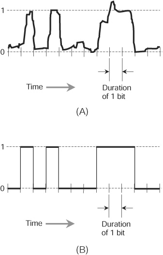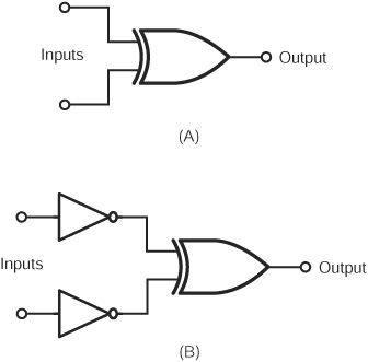
We call an electronic signal digital when it can attain a limited number of well-defined states. Digital signals contrast with analog signals, which can vary over a continuous range, and which can therefore attain a theoretically infinite number of possible instantaneous states. Figure 9-1 shows an example of an analog signal (at A) and an example of a digital signal (at B). In the analog case, the signal strength, also called the amplitude, varies “smoothly” as time passes. In the digital case shown here, the amplitude can attain only two states.
CHAPTER OBJECTIVES
In this chapter, you will
• Compare decimal, binary, octal, and hexadecimal numeration systems.
• Discover how logic gates work.
• See clocks, counters, and black boxes in action.
• Compare storage and speed units.
• Learn the difference between analog and digital data.
• See how circuits can convert between different data formats.
Figure 9-1 · An example of an analog electrical signal (A) that can theoretically have infinitely many states, and an example of a digital signal (B) with only two possible states.
In everyday life, most of us deal with the decimal number system, which makes use of digits from the set
D = {0, 1, 2, 3, 4, 5, 6, 7, 8, 9}
Machines such as computers and communications devices more often use numeration schemes that have some power of 2 digits, such as 2 (21), 4 (22), 8 (23), 16 (24), 32 (25), 64 (26), and so on.
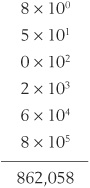
The decimal number system is also called base 10 or radix 10. When we express nonnegative integers in this system, we multiply the right-most digit by 10°, or 1. We multiply the next digit to the left by 101, or 10. The power of 10 increases as we move further to the left. Once we’ve done the digit multiplication, we add up all of the resulting values. For example:
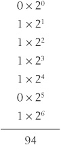
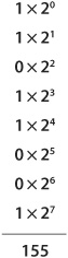
The binary number system provides us with a method of expressing numbers using only the digits 0 and 1. We’ll sometimes hear this system called base 2 or radix 2. When we express nonnegative integers in binary notation, we multiply the rightmost digit by 2°, or 1. The next digit to the left is multiplied by 21, or 2. The power of 2 increases as we continue to the left, so we get a “fours” digit, then an “eights” digit, then a “16s” digit, and so on. For example, consider the decimal number 94. In the binary system, we would write this quantity as 1011110. It breaks down in columnar-sum form as follows:
TIP When we work with a computer or calculator, we input a decimal number to the machine, which converts the number into binary form. The computer or calculator performs all of its arithmetic operations using only the digits 0 and 1. When the computation or calculation process is complete, the machine converts the result back into decimal form for display. In a digital communications or data-storage system, binary numbers can represent alphanumeric characters, shades of color, degrees of temperature, compass directions, acoustic frequencies, and other variable quantities.
Another scheme, sometimes used in computer programming, goes by the name octal number system because it has eight symbols (according to our way of thinking), or 23. Every digit constitutes an element of the set
O = {0,1,2,3,4,5,6,7}
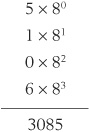
Some people call this system base 8 or radix 8. When we express nonnegative integers in octal notation, we multiply the rightmost digit by 8°, or 1. The next digit to the left is multiplied by 81, or 8. The power of 8 increases as we continue to the left, so we get a “64s” digit, then a “512s” digit, and so on. For example, we render the decimal quantity 3085 in octal form as 6015. We can break it down into the following sum:
Another system used in computer work is the hexadecimal number system. It has 16 (24) symbols: the usual 0 through 9 plus six more, represented by the uppercase English letters A through F. We therefore get the digit set
H = {0, 1, 2, 3, 4, 5, 6, 7, 8, 9, A, B, C, D, E, F}
This system is sometimes called base 16 or radix 16. All of the hexadecimal digits 0 through 9 represent the same values as their decimal counterparts. However, we have the following additional digits:
• Hexadecimal A equals decimal 10
• Hexadecimal B equals decimal 11
• Hexadecimal C equals decimal 12
• Hexadecimal D equals decimal 13
• Hexadecimal E equals decimal 14
• Hexadecimal F equals decimal 15
When we express nonnegative integers in hexadecimal notation, we multiply the rightmost digit by 16°, or 1. We multiply the next digit to the left by 161, or 16. The power of 16 increases as we continue to the left, so we get a “256s” digit, then a “4096s” digit, and so on. For example, we write the decimal quantity 35,898 in hexadecimal form as 8C3A. Remembering that C = 12 and A = 10, we can break the hexadecimal number down into the following sum:
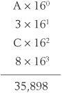
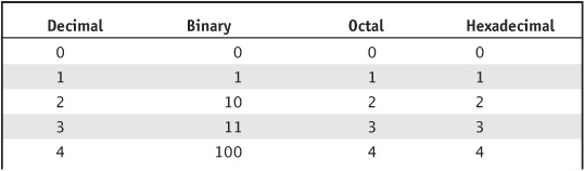
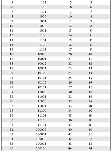
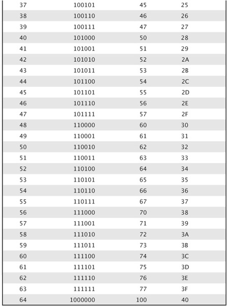
Table 9-1 lists the binary, octal, and hexadecimal equivalents for the decimal numbers 0 through 64.
TABLE 9-1 Binary, octal, and hexadecimal equivalents for decimal numbers 0 through 64.
Express the binary number 10011011 in decimal form.
 SOLUTION
We can add the digits up by going from left to right, or from right to left. It doesn’t matter which way we go, but most people find it easier to keep track of the progression by starting at the “ones” place and working toward the left from there. The digits add up as follows:
 PROBLEM 9-2
Express the decimal number 1,000,000 in hexadecimal form. Warning:This problem involves some tedious arithmetic!
SOLUTION
The values of the digits in a whole (nonfractional) hexadecimal number, proceeding from right to left, constitute ascending nonnegative integer powers of 16. Therefore, a whole hexadecimal number n16 has the form
n =... + (f× 165) + (e × 164) + (d × 163)
+ (c × 162) + (b × 161) + (a × 160)
where a, b, c, d, e, f,... represent single-digit hexadecimal numbers from the set
H = {0,1,2,3,4, 5, 6,7,8,9, A, B, C, D, E, F}
Let’s begin by finding the largest power of 16 that’s less than or equal to 1,000,000. This is 164=65,536. Then, we divide 1,000,000 by 65,536, obtaining 15 plus a remainder. We represent the decimal 15 as the hexadecimal F. Now we know that the hexadecimal expression of the decimal number 1,000,000 has the form
(F × 164) + (d × 163) + (c × 162) + (b × 161) + a =Fdcba
To find the value of d, we note that
15 × 164 = 983,040
This quantity is 16,960 smaller than 1,000,000, so we must find the hexadecimal equivalent of decimal 16,960 and add it to hexadecimal F0000. The largest power of 16 that’s less than or equal to 16,960 is 163, or 4096. We divide 16,960 by 4096 to obtain 4 plus a remainder. Now we know that d = 4 in the above expression, so the decimal 1,000,000 has the hexadecimal form
(F × 164) + (4 × 163) + (c × 162) + (b × 161) + a
= F4cba
To find the value of c, we note that
(F × 164) + (4 × 163) = 983,040 + 16,384
= 999,424
This quantity is 576 smaller than 1,000,000, so we must find the hexadecimal equivalent of decimal 576 and add it to hexadecimal F4000. The largest power of 16 that’s less than or equal to 576 is 162, or 256. We divide 576 by 256 to get 2 plus a remainder. Now we know that c = 2 in the above expression, so the decimal 1,000,000 is equivalent to the hexadecimal
(F × 164) + (4 × 163) + (2 × 162) + (b × 161) + a
=F42ba
To find the value of b, we note that
(Fx164) + (4x163) + (2x162) = 983,040+16,384+512
= 999,936
This quantity is 64 smaller than 1,000,000, so we must find the hexadecimal equivalent of decimal 64 and add it to hexadecimal F4200. The largest power of 16 that’s less than or equal to 64 is 161, or 16. We divide 64 by 16, obtaining 4 without any remainder. Now we know that b = 4 in the above expression, so the decimal 1,000,000 is equivalent to the hexadecimal
(F ×164) + (4 ×163) + (2 ×162) + (4 ×161) + a
= F424a
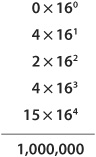
When we found b, we were left with no remainder. Therefore, all the digits to the right of b (in this case, that means only the digit a) must equal 0. We have dragged ourselves through a tedious process, to be sure; but we’ve finally determined that the decimal number 1,000,000 equals the hexadecimal number F4240. To check our work, we can do our arithmetic the other way, converting the hexadecimal number to decimal form, multiplying out the digits from right to left. That’s a lot easier:
All binary (two-state) digital devices and systems employ high-speed electronic switches that perform boolean operations. Engineers call these switches logic gates. Even the most advanced supercomputers consist of logic gates when we break them down to the elemental level.
We might suppose that in electronic logic, the binary digit 1 should stand for “truth” while the binary digit 0 should stand for “falsity.” In so-called positive logic, things work that way. A circuit represents the binary digit 1 with an electrical potential of approximately +5 volts (called the high state or simply high), while the binary digit 0 appears as little or no voltage (called the low state or simply low).
Some electronic systems employ negative logic, in which little or no voltage (the low state) represents logic 1, while +5 volts (the high state) represents logic 0. In another form of negative logic, the digit 1 appears as a negative voltage (such as −5 volts, constituting the low state) and the digit 0 appears as little or no voltage (the high state in this case, because it has the more positive voltage).
TIP In practice, it doesn’t matter what voltage represents which logic state. An electronic logic circuit will work perfectly well as long as the two voltages differ significantly, and as long as they always represent the same logic states as time passes. For the remainder of this discussion, let’s stick to positive logic, where low means logic 0 and high means logic 1.
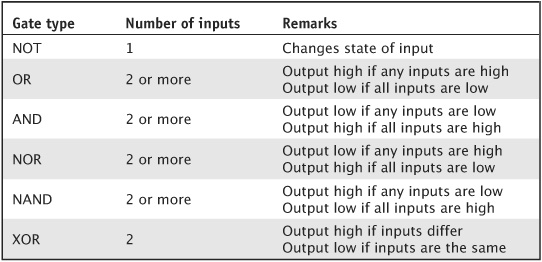
All digital electronic devices employ switches that perform specific logical operations. These switches, called logic gates, can have anywhere from one to several inputs and (usually) a single output. Six basic types of logic gates exist, as follows:
• A logical inverter, also called a NOT gate, has one input and one output. It simply reverses, or inverts, the state of the input. If the input equals 1, then the output equals 0. If the input equals 0, then the output equals 1.
• An OR gate can have two or more inputs (although it usually has only two). If both, or all, of the inputs equal 0, then the output equals 0. If any of the inputs equal 1, then the output equals 1. It only takes one “true” input to make the output of the OR gate “true.” The gate therefore performs an inclusive-OR operation.
• An AND gate can have two or more inputs (although it usually has only two). If both, or all, of the inputs equal 1, then the output equals 1. If any of the inputs equal 0, then the output equals 0.
• An OR gate can be followed by a NOT gate. This combination gives us a NOT-OR gate, more often called a NOR gate. If both, or all, of the inputs equal 0, then the output equals 1. If any of the inputs equal 1, then the output equals 0.
• An AND gate can be followed by a NOT gate. This combination gives us a NOT-AND gate, more often called a NAND gate. If both, or all, of the inputs equal 1, then the output equals 0. If any of the inputs equal 0, then the output equals 1.
• An exclusive OR gate, also called an XOR gate, has two inputs and one output. If the two inputs have the same state (either both 1 or both 0), then the output equals 0. If the two inputs have different states, then the output equals 1.
Table 9-2 summarizes the functions of these logic gates, assuming a single input for the NOT gate and two inputs for the others. Figure 9-2 illustrates the schematic symbols that engineers and technicians use to represent these gates in circuit diagrams.
TABLE 9-2 Logic gates and their characteristics.
Electronics and computer engineers can combine digital logic gates to create massive, almost unbelievably complicated systems having millions or billions of inputs and outputs. No matter how complicated the system might get, the outputs always constitute specific logical functions of the inputs. Engineers sometimes call a complex combination of logic gates a black box.
If an engineer knows the functions of all the logic gates inside a black box, and also knows exactly how the gates are interconnected, then the engineer can define the boolean function that the box performs. Conversely, if an engineer needs a black box to execute a specific logical function, then the engineer can use boolean algebra to break the function down into the six basic operations NOT, OR, AND, NOR, NAND, and XOR, and assemble the gates accordingly.
Figure 9-2 · Schematic symbols for an inverter or NOT gate (A), an AnD gate (B), an oR gate (c), an X oR gate (D), a NAND gate (E), and a NOR gate (F). inputs appear on the left-hand sides of the symbols. Outputs appear on the right-hand sides.
In communications systems, binary data does not exhibit as much sensitivity to noise and interference as analog data does. For this reason, binary systems usually work better than analog systems, producing fewer errors and allowing communication under more adverse circumstances. Since the first digital transmissions took place more than 100 years ago, engineers have invented numerous forms, or modes, of binary communication. Following are three historically well-known binary signaling modes.
• Morse code is the oldest two-state means of sending and receiving messages. The logic states are known as mark (key-closed or on) and space (key-open or off). Morse code is largely obsolete, but some amateur radio operators still use it in their hobby activities, just for fun!
• Baudot, also called the Murray code, is a five-unit digital code not widely used by today’s digital equipment, except in a few antiquated teleprinter systems. There exist 25, or 32, possible representations.
• The American National Standard Code for Information Interchange (ASCII) is a seven-unit code for the transmission of text and simple computer programs. There exist 27, or 128, possible representations.
In electronics, the term clock refers to a circuit that generates pulses at high speed and at precise, constant time intervals. The clock sets the tempo for the operation of digital devices. In a computer, the clock acts like a metronome for the microprocessor. We express or measure clock speeds as frequencies in hertz (Hz). One hertz equals one pulse per second. Higher-frequency units work out as follows:
• A kilohertz (kHz) equals 1000 Hz
• A megahertz (MHz) equals 1,000,000 Hz
• A gigahertz (GHz) equals 1,000,000,000 Hz
• A terahertz (THz) equals 1,000,000,000,000 Hz
In positive logic, a clock generates brief high pulses at regular intervals. The normal state is low.
A counter constitutes an electronic circuit that does exactly what its name suggests: It literally counts digital pulses. Each time the counter receives a high pulse, the binary number in its memory increases by 1. A frequency counter can measure the frequency of an alternating-current (AC) wave or signal by tallying up the cycles over a precisely known period of time. The circuit consists of a gate, which begins and ends each counting cycle at defined intervals. (Don’t confuse this type of gate with the logic gates described a few moments ago!) The counter’s accuracy depends on the gate time, or how long the gate remains open to accept pulses for counting. As we increase the gate time in a frequency counter, accuracy improves.
TIP Although the counter tallies up the pulses as binary numbers, the readout usually appears in base-10 digital numerals for user convenience.
PROBLEM 9-3
Suppose that we place a NOT gate in series (i.e., in cascade) with each of the two inputs of an AND gate. Under what conditions does the output of the resulting black box appear high?
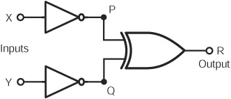
Figure 9-3 illustrates the arrangement of logic gates as a schematic diagram. The inputs appear at points X and Y. We define two intermediate circuit points P and Q, and we call the output point R. At P, we have the condition “NOT X.” At Q, we have the condition” NOT Y.”At R, we have the condition
(NOT X)AND(NOTY)
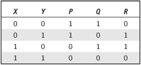
When we compile all of the possible logic states at each of these points, we get Table 9-3, which tells us that the output of the black box is high (logic 1) if and only if both input states are low (logic 0).
Figure 9-3 · Illustration for the solution to Problem 9-3.
TABLE 9-3 solution to Problem 9-3.
PROBLEM 9-4
Suppose that an XOR gate is followed by a NOT gate. Under what conditions does the output of the resulting black box appear low?
SOLUTION
Figure 9-4 shows the sequence of logic gates for this scenario. As before, we call the inputs X and Y. At point P, we have the condition “X NOR Y,” which is high if X and Y have opposite logic states, and low if Xand Yhave the same logic state. At point Q, we have the output condition, which reverses the logic state at point P.Table 9-4 depicts all possible logic states at points X, Y, P, and Q. This table tells us that the output of the black box is low if and only if the input states oppose each other.
Figure 9-4 · Illustration for the solution to Problem 9-4.
TABLE 9-4 Solution to Problem 9-4.
PROBLEM 9-5
Suppose that we place a NOT gate in series with each of the inputs of an XOR gate. Under what conditions will the output of the resulting black box appear high?
SOLUTION
Figure 9-5 shows the arrangement of logic gates in this situation. At point P, we have the condition “NOT X.” At point Q, we have the condition “NOT Y.” At point R, we have
(NOT X)XOR(NOT Y)
Table 9-5 is a compilation of all possible states. We can see that the output of the black box is high if and only if the input states are opposite.
Figure 9-5 · Illustration for the solution to Problem 9-5.
TABLE 9-5 solution to Problem 9-5.
The use of binary data provides excellent communications accuracy, efficiency, and reliability. If we need to have more than two logic states (a condition known as multilevel signaling), then we can represent all the levels as sequences of binary digits. A sequence of three binary digits, for example, can represent 23, or eight, levels. A sequence of four binary digits can represent 24, or 16, levels. Communications engineers and technophiles compress the term binary digit into the single word bit.
We can always represent a digital bit as either logic 0 or logic 1. A group of eight bits constitutes a unit called an octet. In many systems, an octet corresponds to a byte. We can express in large units according to powers of 10, as follows:
• A kilobit (kb) equals 1000 bits
• A megabit (Mb) equals 1,000,000 bits
• A gigabit (Gb) equals 1,000,000,000 bits
• A terabit (Tb) equals 1,000,000,000,000 bits
If you hear about a computer modem (modulator/demodulator) that operates at 50 Mbps, it means 50,000,000 bits per second (bps). Bits, kilobits, megabits, gigabits, and terabits per second (bps, kbps, Mbps, Gbps, and Tbps) express data speeds, also called data transfer rates, in digital communications networks.
Data that resides in computer storage or memory (as opposed to “flowing” from point to point in a network) is usually quantified as follows:
• A kilobyte (KB) equals 210 or 1024 bytes
• A megabyte (MB) equals 220 or 1,048,576 bytes
• A gigabyte (GB) equals 230 or 1,073,741,824 bytes
• A terabyte (TB) equals 240 or 1,099,511,627,776 bytes
TIP Note that we abbreviate bits as a lowercase b, but we abbreviate bytes as an uppercase B. We represent 103 (the decimal prefix multiplier kilo-) as a lowercase k, but 210 (the binary prefix multiplier kilo-) gets an uppercase K. The prefix multipliers mega-, giga-, and tera- are abbreviated as uppercase letters M, G, and T, respectively, whether we’re working with “bunches of bits” (powers of 10) or “bunches of bytes” (powers of 2).
Larger units for static data (stored as opposed to moving) have become common in recent years, as computer memory and storage media continue to expand in capacity. Therefore, you should expect to encounter units such as the following more and more often in the future:
• A petabyte (PB) equals 250 bytes, or 1024 TB
• An exabyte (EB) equals 260 bytes, or 1024 PB
The term baud refers to the number of times per second that a signal changes its logic state. The units of bps (bits per second) and baud are not equivalent, although people often think or speak of them that way. You won’t encounter this term very often.
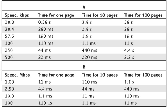
TABLE 9-6 Lengths of time required to send text data at various speeds. Abbreviations are as follows: kbps = kilobits per second (units of 1000 bits per second), Mbps = megabits per second (units of 1,000,000 bits per second), s = seconds, μs = milliseconds (units of 0.001 second), and μs = microseconds (units of 0.000001 second).
In a computer network, each computer or terminal has a modem connecting it to the communications medium (cable, optical fiber, wireless link, telephone line, or whatever). When two machines exchange digital data, the slower modem determines the maximum possible data speed. Table 9-6 shows some examples of data speeds and the approximate time periods required to send 1, 10, and 100 pages of double-spaced, typewritten text at each speed.
We can convert any analog signal into a string of pulses whose amplitudes can attain a limited number of digital states. We call this process analog-to-digital (A/D) conversion. In a computer or communications system, we can use an A/D converter to change voices, pictures, music, or test-instrument readings into signals that a digital machine can “understand.” In a high-fidelity audio recording system, we can convert music from analog to digital form for storage on media such as compact discs (CDs) or digital versatile discs (DVDs). Digital signals suffer much less than analog signals from the adverse effects of noise and interference. Also, we can get many more digital signals than analog signals into any given circuit, onto any given communications line, or onto any given storage medium.
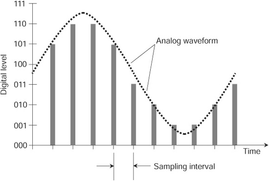
An A/D converter works by “checking” the level of an analog signal every so-often, and then rounding it off to the nearest standard digital level, a process known as sampling. An analog signal resembles a smooth hillside, while the equivalent digital signal resembles a terraced hillside with each terrace representing one sample. Some A/D converters have only a few levels, or states, in their outputs; others have many. We call the number of possible digital states the sampling resolution. Some A/D converters take many samples every second, while others take only a few. The number of samples taken per second constitutes the sampling rate.
In most A/D converters, the sampling resolution equals a positive-integer power of 2. A sampling resolution of eight levels (Fig. 9-6) is sufficient for voice communications. A resolution of 16 levels is good enough for music transmission or recording of fair quality. For video signals, such as we might find in high-speed animated computer graphics or virtual reality (VR), we need a higher sampling resolution.
Figure 9-6 · An analog waveform (dashed curve) and an eight-level digital representation of that waveform (vertical bars).
The precision with which we can digitize an analog signal depends on the sampling rate. In general, the sampling rate must equal at least twice the highest data frequency if we expect to get a reasonable digital facsimile of a given analog signal. For a voice signal with components as high as 3 kHz, the minimum sampling rate is 6 kHz, representing one sample every 167 microseconds (|J, s], where 1 |J, s = 0.000001 second (s). In industrial-level computer-aided design (CAD), gaming, high-definition television (HDTV), or virtual reality (VR), we will need a sampling rate on the order of several megahertz.
Digital-to-analog (D/A) conversion does the opposite of A/D conversion. The D/A process converts a digital signal to an equivalent analog signal at the receiving end (or destination) in a communications circuit where A/D conversion is done at the transmitting end (or source). We can use D/A conversion to reproduce digitized sound recordings, such as those found on a CD, DVD, computer flash drive, or computer hard drive.
In recording and reproduction, we can copy a digital selection repeatedly, and the quality does not diminish. With older analog recording and reproduction equipment, the fourth or fifth “generation” always ended up sounding or looking bad, regardless of the quality of the equipment used. Of course, no data transmission, storage, or retrieval system works perfectly. Errors occasionally creep into digital systems. A circuit will sometimes mistake a logic 1 for a logic 0 or vice versa. Such errors accumulate over time, and as generation after generation of copies are made. But in general, digital systems represent a huge technological improvement over analog systems, because digital errors occur far less often, and have less effect overall, than analog imperfections.
The methodology for D/A conversion depends on whether the signal is purely binary (consisting of only two logic states) or multilevel, with a number of states corresponding to some integer power of 2 (such as 4, 8, 16, or 32). Generally, D/A conversion is done by a microprocessor that undoes what an A/D converter originally did. We can convert a multilevel digital signal to its analog equivalent by “smoothing out” the pulses. (Imagine the train of pulses in Fig. 9-6 contoured into the dashed curve.)
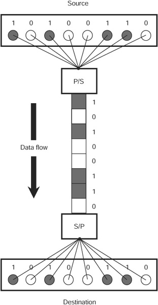
We can send and receive binary digital data one bit at a time along a single line or channel using a mode called serial data transmission. We can send and receive data at much greater speeds, however, by using multiple lines or a wideband channel, sending independent sequences of bits along each line or subchannel, a mode known as parallel data transmission.
A parallel-to-serial (P/S) converter receives bits from multiple lines or channels, and then retransmits them one at a time along a single line or channel. A buffer stores the bits from the parallel lines or channels, placing the bits in a queue for controlled, slower transmission along the serial line or channel. A serial-to-parallel (S/P) converter takes incoming bits from a serial line or channel, and resends the bits out in batches along multiple parallel lines or channels. Figure 9-7 illustrates a communications link using a P/S converter at the source and an S/P converter at the destination.
An electronic technology called digital signal processing (DSP) can improve the precision of digital data. The process enhances the quality of marginal or weak signals, so that the receiving equipment makes fewer errors. Binary digital signals have well-defined patterns that computers can easily recognize and clarify.
A DSP system minimizes or eliminates confusion between digital states that can result from electrical noise. In Fig. 9-8A, we see a hypothetical “noisy” binary digital signal before DSP. At B, we see the same signal after DSP has “cleaned it up.”
TIP The DSP circuit makes logic-state “decisions” at defined, constant time intervals equal to a the duration of a bit. If the average strength of the incoming signal exceeds a certain level over the time interval, the output equals 1. If the average signal strength remains below another defined critical level for a certain time interval, the output equals 0.
Our eyes and brains perceive color as a function of three independent radiant-light characteristics. When much of the energy in a ray or beam of visible light exists near a single wavelength, we see an intense hue. We define the vividness or “purity” of a hue as the saturation. We define the brightness of a particular hue as a function of how much total energy the light contains at the wavelength representing that hue. We can obtain a light ray or beam having any imaginable hue, saturation level, and brightness level by combining red, green, and blue light in various proportions. The digital red/green/blue (RGB) color model takes advantage of this fact.
Figure 9-7 · A communications circuit employing parallel-to-serial (P/S) conversion at the source, and serial-to-parallel (S/P) conversion at the destination.
Figure 9-8 · Digital signal processing (DSP) can “clean up” a noisy digital signal (A), producing an output with well-defined logic states (B).
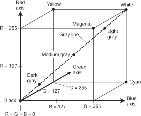
We can generate a color palette by combining pure red, green, and blue in various ratios, assigning each primary color an axis in rectangular three-dimensional (3D) space as shown in Fig. 9-9. We call the axes R (for red), G (for green), and B (for blue). The color intensity along each axis can range from 0 (the complete absence of energy) to 255 (the greatest possible amount of energy that the system can provide). The equivalent range in binary numeration goes from 00000000 to 11111111. When we combine all three color axes into a “3D color space” with 256 possible brightness values along each axis, we obtain 256 x 256 x 256, or 16,777,216, possible colors. We can represent each color as a unique point inside the geometric cube defined by the three perpendicular axes.
FIGURE, 9-9 • In the RGB color model, visible-light colors can be represented as points inside a cube.
 Still Struggling
Some engineers represent individual colors in the RGB model as six-digit hexadecimal numbers such as 005CFF. In this scheme, the first two digits represent the red (R) intensity in 256 levels ranging from 00 to FF. The middle two digits represent the green (G) intensity, again in 256 levels ranging from 00 to FF. The last two digits represent the blue (B) intensity, once again in 256 levels ranging from 00 to FF.
Suppose that we want to list all of the possible conditions that an n-bit binary digital signal can attain, where n is a positive integer. What general rule can we use?
SOLUTION
We can count upward in binary form from 0, writing every binary numeral as a sequence of n digits, until all of the digits equal 1.
PROBLEM 9-7
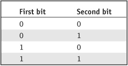
Using the rule described in the solution to Problem 9-6, list all of the conditions that a 2-bit binary digital signal can attain.
SOLUTION
See Table 9-7.
TABLE 9-7 Solution to Problem 9-7.
PROBLEM 9-8
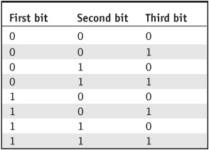
Using the rule described in the solution to Problem 9-6, list all of the conditions that a 3-bit binary digital signal can attain.
SOLUTION
See Table 9-8.
TABLE 9-8 Solution to Problem 9-8.
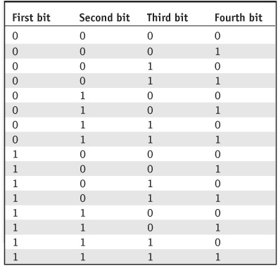
PROBLEM 9-9
Using the rule described in the solution to Problem 9-6, list all of the conditions that a 4-bit binary digital signal can attain.
SOLUTION
See Table 9-9.
TABLE 9-9 Solution to Problem 9-9.
You may refer to the text in this chapter while taking this quiz. A good score is at least 8 correct. Answers are in the back of the book.
1. Which of the following binary numbers is equivalent to the decimal 129?
A. 1111111
B. 11111111
C. 1000001
D. 10000001
2. Which of the following decimal numbers is equivalent to the hexadecimal F23?
A. 3875
B. 1523
C. 251
D. 20
3. In the hexadecimal number system, what number follows 999?
A. 1000
B. 99A
C. A000
D. A99
4. Suppose that we design an electronic music system using 9-digit binary numbers to represent various audio frequencies. Each binary number represents one, but only one, particular frequency. How many possible frequencies can such a system represent?
A. 64
B. 512
C. 1024
D. 2048
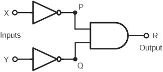
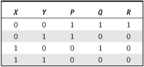
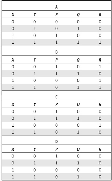
5. Figure 9-10 illustrates a circuit built of logic gates. Tables 9-10A through 9-10D show four possible representations for the states in this circuit. Which of these four tables correctly represents the circuit states at all five points X, Y, P, Q, and R?
A. Table 9-10A
B. Table 9-10B
c. Table 9-10C
D. Table 9-10D
Figure 9-10 · Illustration for Quiz Question 5.
TABLE 9-10 Possible solutions to Quiz Question 5.
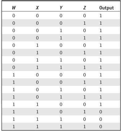
TABLE 9-11 Logic states for Quiz Question 6.
6. Table 9-11 outlines all possible logic states for a digital circuit with four inputs W, X, Y, and Z. Figure 9-11 shows four different arrangements of logic gates. Which circuit in the figure produces the logic states in the table?
A. Figure 9-11A
B. Figure 9-11B
C. Figure 9-11C
D. Figure 9-11D
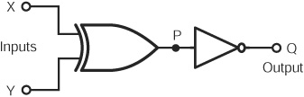
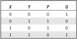
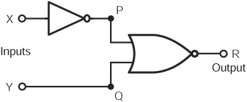
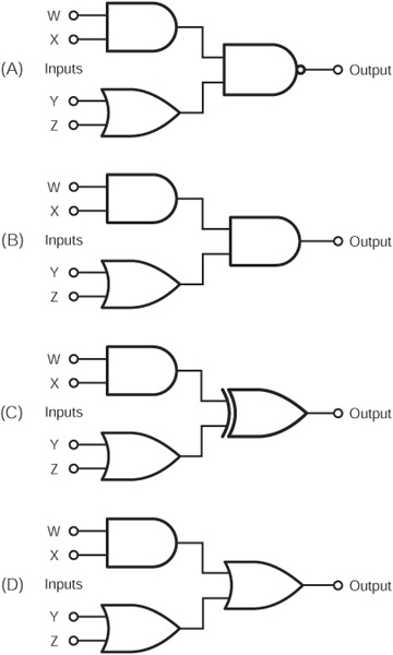
7. Figure 9-12 illustrates two electronic circuits. If we think of them as black boxes, how do their logic functions compare?
A. for any given set of inputs, the output from black box A is opposite the output from black box B.
B. The output from black box A is high if and only if the inputs differ, but the output from black box B is high ifand only ifthe inputs are the same.
C. The output from black box A is high if and only if the inputs differ, but the output from black box B is high if and only if both inputs are high.
D. for any given set of inputs, the output from black box A is the same as the output from black box B. in other words, the two black boxes perform identical logic functions.
Figure 9-11 · Illustration for Quiz Question 6.
Figure 9-12 · Illustration for Quiz Question 7.
8. Suppose that we want to convert an analog signal whose maximum frequency is 1000 kHz into a digital signal of acceptable quality. We should take samples at time intervals of
A. 1000 u.s or less.
B. 500.0 u.s or less.
C. 1.000 u.s or less.
D. 0.5000 u.s or less.
9. Suppose that we want to convert an analog video signal into a digital signal of acceptable quality. The minimum acceptable sampling resolution is
A. dependent on the image quality we want.
B. 32 levels.
C. 1024 levels.
D. 1,048,576 levels.
10. Imagine an RGB color model in which the red, green, and blue signals can each attain 32 discrete levels. This model can uniquely represent
A. 1024 different colors.
B. 4096 different colors.
C. 32,768 different colors.
D. 65,536 different colors.