The first thing I saw as I walked through the door was a complete class diagram printed on large sheets of paper that covered a large wall. It was my first day on a project in which smart people had spent months carefully researching and developing a detailed model of the domain. The typical object in the model had intricate associations with three or four other objects, and this web of associations had few natural borders. In this respect, the analysts had been true to the nature of the domain.
As overwhelming as the wall-size diagram was, the model did capture some knowledge. After a moderate amount of study, I learned quite a bit (though that learning was hard to direct—much like randomly browsing the Web). I was more troubled to find that my study gave no insight into the application’s code and design.
When the developers had begun implementing the application, they had quickly discovered that the tangle of associations, although navigable by a human analyst, didn’t translate into storable, retrievable units that could be manipulated with transactional integrity. Mind you, this project was using an object database, so the developers didn’t even have to face the challenges of mapping objects into relational tables. At a fundamental level, the model did not provide a guide to implementation.
Because the model was “correct,” the result of extensive collaboration between technical analysts and business experts, the developers reached the conclusion that conceptually based objects could not be the foundation of their design. So they proceeded to develop an ad hoc design. Their design did use a few of the same class names and attributes for data storage, but it was not based on the existing, or any, model.
The project had a domain model, but what good is a model on paper unless it directly aids the development of running software?
A few years later, I saw the same end result come from a completely different process. This project was to replace an existing C++ application with a new design implemented in Java. The old application had been hacked together without any regard for object modeling. The design of the old application, if there was one, had accreted as one capability after another had been laid on top of the existing code, without any noticeable generalization or abstraction.
The eerie thing was that the end products of the two processes were very similar! Both had functionality, but were bloated, very hard to understand, and eventually unmaintainable. Though the implementations had, in places, a kind of directness, you couldn’t gain much insight about the purpose of the system by reading the code. Neither process took any advantage of the object paradigm available in their development environment, except as fancy data structures.
Models come in many varieties and serve many roles, even those restricted to the context of a software development project. Domain-driven design calls for a model that doesn’t just aid early analysis but is the very foundation of the design. This approach has some important implications for the code. What is less obvious is that domain-driven design requires a different approach to modeling. . . .
The astrolabe, used to compute star positions, is a mechanical implementation of a model of the sky.
Tightly relating the code to an underlying model gives the code meaning and makes the model relevant.

Projects that have no domain model at all, but just write code to fulfill one function after another, gain few of the advantages of knowledge crunching and communication discussed in the previous two chapters. A complex domain will swamp them.
On the other hand, many complex projects do attempt some sort of domain model, but they don’t maintain a tight connection between the model and the code. The model they develop, possibly useful as an exploratory tool at the outset, becomes increasingly irrelevant and even misleading. All the care lavished on the model provides little reassurance that the design is correct, because the two are different.
This connection can break down in many ways, but the detachment is often a conscious choice. Many design methodologies advocate an analysis model, quite distinct from the design and usually developed by different people. It is called an analysis model because it is the product of analyzing the business domain to organize its concepts without any consideration of the part it will play in a software system. An analysis model is meant as a tool for understanding only; mixing in implementation concerns is thought to muddy the waters. Later, a design is created that may have only a loose correspondence to the analysis model. The analysis model is not created with design issues in mind, and therefore it is likely to be quite impractical for those needs.
Some knowledge crunching happens during such an analysis, but most of it is lost when coding begins, when the developers are forced to come up with new abstractions for the design. Then there is no guarantee that the insights gained by the analysts and embedded in the model will be retained or rediscovered. At this point, maintaining any mapping between the design and the loosely connected model is not cost-effective.
The pure analysis model even falls short of its primary goal of understanding the domain, because crucial discoveries always emerge during the design/implementation effort. Very specific, unanticipated problems always arise. An up-front model will go into depth about some irrelevant subjects, while it overlooks some important subjects. Other subjects will be represented in ways that are not useful to the application. The result is that pure analysis models get abandoned soon after coding starts, and most of the ground has to be covered again. But the second time around, if the developers perceive analysis to be a separate process, modeling happens in a less disciplined way. If the managers perceive analysis to be a separate process, the development team may not be given adequate access to domain experts.
Whatever the cause, software that lacks a concept at the foundation of its design is, at best, a mechanism that does useful things without explaining its actions.
If the design, or some central part of it, does not map to the domain model, that model is of little value, and the correctness of the software is suspect. At the same time, complex mappings between models and design functions are difficult to understand and, in practice, impossible to maintain as the design changes. A deadly divide opens between analysis and design so that insight gained in each of those activities does not feed into the other.
An analysis must capture fundamental concepts from the domain in a comprehensible, expressive way. The design has to specify a set of components that can be constructed with the programming tools in use on the project that will perform efficiently in the target deployment environment and will correctly solve the problems posed for the application.
MODEL-DRIVEN DESIGN discards the dichotomy of analysis model and design to search out a single model that serves both purposes. Setting aside purely technical issues, each object in the design plays a conceptual role described in the model. This requires us to be more demanding of the chosen model, since it must fulfill two quite different objectives.
There are always many ways of abstracting a domain, and there are always many designs that can solve an application problem. This is what makes it practical to bind the model and design. This binding mustn’t come at the cost of a weakened analysis, fatally compromised by technical considerations. Nor can we accept clumsy designs, reflecting domain ideas but eschewing software design principles. This approach demands a model that works well as both analysis and design. When a model doesn’t seem to be practical for implementation, we must search for a new one. When a model doesn’t faithfully express the key concepts of the domain, we must search for a new one. The modeling and design process then becomes a single iterative loop.
The imperative to relate the domain model closely to the design adds one more criterion for choosing the more useful models out of the universe of possible models. It calls for hard thinking and usually takes multiple iterations and a lot of refactoring, but it makes the model relevant.
Therefore:
Design a portion of the software system to reflect the domain model in a very literal way, so that mapping is obvious. Revisit the model and modify it to be implemented more naturally in software, even as you seek to make it reflect deeper insight into the domain. Demand a single model that serves both purposes well, in addition to supporting a robust UBIQUITOUS LANGUAGE.
Draw from the model the terminology used in the design and the basic assignment of responsibilities. The code becomes an expression of the model, so a change to the code may be a change to the model. Its effect must ripple through the rest of the project’s activities accordingly.
To tie the implementation slavishly to a model usually requires software development tools and languages that support a modeling paradigm, such as object-oriented programming.
Sometimes there will be different models for different subsystems (see Chapter 14), but only one model should apply to a particular part of the system, throughout all aspects of the development effort, from the code to requirements analysis.
The single model reduces the chances of error, because the design is now a direct outgrowth of the carefully considered model. The design, and even the code itself, has the communicativeness of a model.
Developing a single model that captures the problem and provides a practical design is easier said than done. You can’t just take any model and turn it into a workable design. The model has to be carefully crafted to make for a practical implementation. Design and implementation techniques have to be employed that allow code to express a model effectively (see Part II). Knowledge crunchers explore model options and refine them into practical software elements. Development becomes an iterative process of refining the model, the design, and the code as a single activity (see Part III).
To make a MODEL-DRIVEN DESIGN pay off, the correspondence must be literal, exact within bounds of human error. To make such a close correspondence of model and design possible, it is almost essential to work within a modeling paradigm supported by software tools that allow you to create direct analogs to the concepts in the model.
Figure 3.1
Object-oriented programming is powerful because it is based on a modeling paradigm, and it provides implementations of the model constructs. As far as the programmer is concerned, objects really exist in memory, they have associations with other objects, they are organized into classes, and they provide behavior available by messaging. Although many developers benefit from just applying the technical capabilities of objects to organize program code, the real breakthrough of object design comes when the code expresses the concepts of a model. Java and many other tools allow the creation of objects and relationships directly analogous to conceptual object models.
Although it has never reached the mass usage that object-oriented languages have, the Prolog language is a natural fit for MODEL-DRIVEN DESIGN. In this case, the paradigm is logic, and the model is a set of logical rules and facts they operate on.
MODEL-DRIVEN DESIGN has limited applicability using languages such as C, because there is no modeling paradigm that corresponds to a purely procedural language. Those languages are procedural in the sense that the programmer tells the computer a series of steps to follow. Although the programmer may be thinking about the concepts of the domain, the program itself is a series of technical manipulations of data. The result may be useful, but the program doesn’t capture much of the meaning. Procedural languages often support complex data types that begin to correspond to more natural conceptions of the domain, but these complex types are only organized data, and they don’t capture the active aspects of the domain. The result is that software written in procedural languages has complicated functions linked together based on anticipated paths of execution, rather than by conceptual connections in the domain model.
Before I ever heard of object-oriented programming, I wrote FORTRAN programs to solve mathematical models, which is just the sort of domain in which FORTRAN excels. Mathematical functions are the main conceptual component of such a model and can be cleanly expressed in FORTRAN. Even so, there is no way to capture higher level meaning beyond the functions. Most non-mathematical domains don’t lend themselves to MODEL-DRIVEN DESIGN in procedural languages because the domains are not conceptualized as math functions or as steps in a procedure.
Object-oriented design, the paradigm that currently dominates the majority of ambitious projects, is the approach used primarily in this book.
As discussed in Chapter 1, a printed circuit board (PCB) can be viewed as a collection of electrical conductors (called nets) connecting the pins of various components. There are often tens of thousands of nets. Special software, called a PCB layout tool, finds a physical arrangement for all the nets so that they don’t cross or interfere with each other. It does this by optimizing their paths while satisfying an enormous number of constraints placed by the human designers that restrict the way they can be laid out. Although PCB layout tools are very sophisticated, they still have some shortcomings.
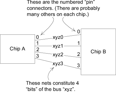
One problem is that each of these thousands of nets has its own set of layout rules. PCB engineers see many nets as belonging to natural groupings that should share the same rules. For example, some nets form buses.
Figure 3.2. An explanatory diagram of buses and nets
By lumping nets into a bus, perhaps 8 or 16 or 256 at a time, the engineer cuts the job down to a more manageable size, improving productivity and reducing errors. The trouble is, the layout tool has no such concept as a bus. Rules have to be assigned to tens of thousands of nets, one net at a time.
Desperate engineers worked around this limitation in the layout tool by writing scripts that parse the layout tool’s data files and insert rules directly into the file, applying them to an entire bus at a time.
The layout tool stores each circuit connection in a net list file, which looks something like this:
Net Name Component.Pin
-------- -------------
Xyz0 A.0, B.0
Xyz1 A.1, B.1
Xyz2 A.2, B.2
. . .
It stores the layout rules in a file format something like this:
Net Name Rule Type Parameters
-------- --------- ----------
Xyz1 min_linewidth 5
Xyz1 max_delay 15
Xyz2 min_linewidth 5
Xyz2 max_delay 15
. . .
The engineers carefully use a naming convention for the nets so that an alphabetical sort of the data file will place the nets of a bus together in a sorted file. Then their script can parse the file and modify each net based on its bus. Actual code to parse, manipulate, and write the files is just too verbose and opaque to serve this example, so I’ll just list the steps in the procedure.
1. Sort net list file by net name.
2. Read each line in file, seeking first one that starts with bus name pattern.
3. For each line with matching name, parse line to get net name.
4. Append net name with rule text to rules file.
5. Repeat from 3 until left of line no longer matches bus name.
So the input of a bus rule such as this:
Bus Name Rule Type Parameters
-------- --------- ----------
Xyz max_vias 3
would result in adding net rules to the file like these:
Net Name Rule Type Parameters
-------- --------- ----------
. . .
Xyz0 max_vias 3
Xyz1 max_vias 3
Xyz2 max_vias 3
. . .
I imagine that the person who first wrote such a script had only this simple need, and if this were the only requirement, a script like this would make a lot of sense. But in practice, there are now dozens of scripts. They could, of course, be refactored to share sorting and string matching functions, and if the language supported function calls to encapsulate the details, the scripts could begin to read almost like the summary steps above. But still, they are just file manipulations. A different file format (and there are several) would require starting from scratch, even though the concept of grouping buses and applying rules to them is the same. If you wanted richer functionality or interactivity, you would have to pay for every inch.
What the script writers were trying to do was to supplement the tool’s domain model with the concept of “bus.” Their implementation infers the bus’s existence through sorts and string matches, but it does not explicitly deal with the concept.
The preceding discussion has already described the concepts the domain experts use to think about their problems. Now we need to organize those concepts explicitly into a model we can base software on.
Figure 3.3. A class diagram oriented toward efficient assignment of layout rules
With these objects implemented in an object-oriented language, the core functionality becomes almost trivial.
The assignRule() method can be implemented on Abstract Net. The assignedRules() method on Net takes its own rules and its Bus’s rules.
abstract class AbstractNet {
private Set rules;
void assignRule(LayoutRule rule) {
rules.add(rule);
}
Set assignedRules() {
return rules;
}
}
class Net extends AbstractNet {
private Bus bus;
Set assignedRules() {
Set result = new HashSet();
result.addAll(super.assignedRules());
result.addAll(bus.assignedRules());
return result;
}
}
Of course, there would be a great deal of supporting code, but this covers the basic functionality of the script.
The application requires import/export logic, which we’ll encapsulate into some simple services.

We’ll also need a few utilities:
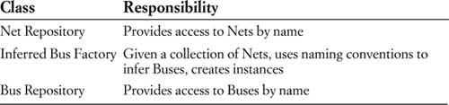
Now, starting the application is a matter of initializing the repositories with imported data:
Collection nets = NetListImportService.read(aFile);
NetRepository.addAll(nets);
Collection buses = InferredBusFactory.groupIntoBuses(nets);
BusRepository.addAll(buses);
Each of the services and repositories can be unit-tested. Even more important, the core domain logic can be tested. Here is a unit test of the most central behavior (using the JUnit test framework):
public void testBusRuleAssignment() {
Net a0 = new Net("a0");
Net a1 = new Net("a1");
Bus a = new Bus("a"); //Bus is not conceptually dependent
a.addNet(a0); //on name-based recognition, and so
a.addNet(a1); //its tests should not be either.
NetRule minWidth4 = NetRule.create(MIN_WIDTH, 4);
a.assignRule(minWidth4);
assertTrue(a0.assignedRules().contains(minWidth4));
assertEquals(minWidth4, a0.getRule(MIN_WIDTH));
assertEquals(minWidth4, a1.getRule(MIN_WIDTH));
}
An interactive user interface could present a list of buses, allowing the user to assign rules to each, or it could read from a file of rules for backward compatibility. A façade makes access simple for either interface. Its implementation echoes the test:
public void assignBusRule(String busName, String ruleType,
double parameter){
Bus bus = BusRepository.getByName(busName);
bus.assignRule(NetRule.create(ruleType, parameter));
}
Finishing:
NetRuleExport.write(aFileName, NetRepository.allNets());
(The service asks each Net for assignedRules(), and then writes them fully expanded.)
Of course, if there were only one operation (as in the example), the script-based approach might be just as practical. But in reality, there were 20 or more. The MODEL-DRIVEN DESIGN scales easily and can include constraints on combining rules and other enhancements.
The second design also accommodates testing. Its components have well-defined interfaces that can be unit-tested. The only way to test the script is to do an end-to-end file-in/file-out comparison.
Keep in mind that such a design does not emerge in a single step. It would take several iterations of refactoring and knowledge crunching to distill the important concepts of the domain into a simple, incisive model.
In theory, perhaps, you could present a user with any view of a system, regardless of what lies beneath. But in practice, a mismatch causes confusion at best—bugs at worst. Consider a very simple example of how users are misled by superimposed models of bookmarks for Web sites in current releases of Microsoft Internet Explorer.1
A user of Internet Explorer thinks of “Favorites” as a list of names of Web sites that persist from session to session. But the implementation treats a Favorite as a file containing a URL, and whose filename is put in the Favorites list. That’s a problem if the Web page title contains characters that are illegal in Windows filenames. Suppose a user tries to store a Favorite and types the following name for it: “Laziness: The Secret to Happiness”. An error message will say: “A filename cannot contain any of the following characters: \ / : * ? " < > | ”. What filename? On the other hand, if the Web page title already contains an illegal character, Internet Explorer will just quietly strip it out. The loss of data may be benign in this case, but not what the user would have expected. Quietly changing data is completely unacceptable in most applications.
MODEL-DRIVEN DESIGN calls for working with only one model (within any single context, as will be discussed in Chapter 14). Most of the advice and examples go to the problems of having separate analysis models and design models, but here we have a problem arising from a different pair of models: the user model and the design/implementation model.
Of course, an unadorned view of the domain model would definitely not be convenient for the user in most cases. But trying to create in the UI an illusion of a model other than the domain model will cause confusion unless the illusion is perfect. If Web Favorites are actually just a collection of shortcut files, then expose this fact to the user and eliminate the confusing alternative model. Not only will the feature be less confusing, but the user can then leverage what he knows about the file system to deal with Web Favorites. He can reorganize them with the File Explorer, for example, rather than use awkward tools built into the Web browser. Informed users would be more able to exploit the flexibility of storing Web shortcuts anywhere in the file system. Just by removing the misleading extra model, the power of the application would increase and become clearer. Why make the user learn a new model when the programmers felt the old model was good enough?
Alternatively, store the Favorites in a different way, say in a data file, so that they can be subject to their own rules. Those rules would presumably be the naming rules that apply to Web pages. That would again provide a single model. This one tells the user that everything he knows about naming Web sites applies to Favorites.
When a design is based on a model that reflects the basic concerns of the users and domain experts, the bones of the design can be revealed to the user to a greater extent than with other design approaches. Revealing the model gives the user more access to the potential of the software and yields consistent, predictable behavior.
Manufacturing is a popular metaphor for software development. One inference from this metaphor: highly skilled engineers design; less skilled laborers assemble the products. This metaphor has messed up a lot of projects for one simple reason—software development is all design. All teams have specialized roles for members, but overseparation of responsibility for analysis, modeling, design, and programming interferes with MODEL-DRIVEN DESIGN.
On one project, my job was to coordinate different application teams and help develop the domain model that would drive the design. But the management thought that modelers should be modeling, and that coding was a waste of those skills, so I was in effect forbidden to program or work on details with programmers.
Things seemed to be OK for a while. Working with domain experts and the development leads of the different teams, we crunched knowledge and refined a nice core model. But that model was never put to work, for two reasons.
First, some of the model’s intent was lost in the handoff. The overall effect of a model can be very sensitive to details (as will be discussed in Parts II and III), and those details don’t always come across in a UML diagram or a general discussion. If I could have rolled up my sleeves and worked with the other developers directly, providing some code to follow as examples, and providing some close support, the team could have taken up the abstractions of the model and run with them.
The other problem was the indirectness of feedback from the interaction of the model with the implementation and the technology. For example, certain aspects of the model turned out to be wildly inefficient on our technology platform, but the full implications didn’t trickle back to me for months. Relatively minor changes could have fixed the problem, but by then it didn’t matter. The developers were well on their way to writing software that did work—without the model, which had been reduced to a mere data structure, wherever it was still used at all. The developers had thrown the baby out with the bathwater, but what choice did they have? They could no longer risk being saddled with the dictates of the architect in the ivory tower.
The initial circumstances of this project were about as favorable to a hands-off modeler as they ever are. I already had extensive hands-on experience with most of the technology used on the project. I had even led a small development team on the same project before my role changed, so I was familiar with the project’s development process and programming environment. Even those factors were not enough to make me effective, given the separation of modeler from implementation.
If the people who write the code do not feel responsible for the model, or don’t understand how to make the model work for an application, then the model has nothing to do with the software. If developers don’t realize that changing code changes the model, then their refactoring will weaken the model rather than strengthen it. Meanwhile, when a modeler is separated from the implementation process, he or she never acquires, or quickly loses, a feel for the constraints of implementation. The basic constraint of MODEL-DRIVEN DESIGN—that the model supports an effective implementation and abstracts key domain knowledge—is half-gone, and the resulting models will be impractical. Finally, the knowledge and skills of experienced designers won’t be transferred to other developers if the division of labor prevents the kind of collaboration that conveys the subtleties of coding a MODEL-DRIVEN DESIGN.
The need for HANDS-ON MODELERS does not mean that team members cannot have specialized roles. Every Agile process, including Extreme Programming, defines roles for team members, and other informal specializations tend to emerge naturally. The problem arises from separating two tasks that are coupled in a MODEL-DRIVEN DESIGN, modeling and implementation.
The effectiveness of an overall design is very sensitive to the quality and consistency of fine-grained design and implementation decisions. With a MODEL-DRIVEN DESIGN, a portion of the code is an expression of the model; changing that code changes the model. Programmers are modelers, whether anyone likes it or not. So it is better to set up the project so that the programmers do good modeling work.
Therefore:
Any technical person contributing to the model must spend some time touching the code, whatever primary role he or she plays on the project. Anyone responsible for changing code must learn to express a model through the code. Every developer must be involved in some level of discussion about the model and have contact with domain experts. Those who contribute in different ways must consciously engage those who touch the code in a dynamic exchange of model ideas through the UBIQUITOUS LANGUAGE.
The sharp separation of modeling and programming doesn’t work, yet large projects still need technical leaders who coordinate high-level design and modeling and help work out the most difficult or most critical decisions. Part IV, “Strategic Design,” deals with such decisions and should stimulate ideas for more productive ways to define the roles and responsibilities of high-level technical people.
Domain-driven design puts a model to work to solve problems for an application. Through knowledge crunching, a team distills a torrent of chaotic information into a practical model. A MODEL-DRIVEN DESIGN intimately connects the model and the implementation. The UBIQUITOUS LANGUAGE is the channel for all that information to flow between developers, domain experts, and the software.
The result is software that provides rich functionality based on a fundamental understanding of the core domain.
As mentioned, success with MODEL-DRIVEN DESIGN is sensitive to detailed design decisions, which is the subject of the next several chapters.