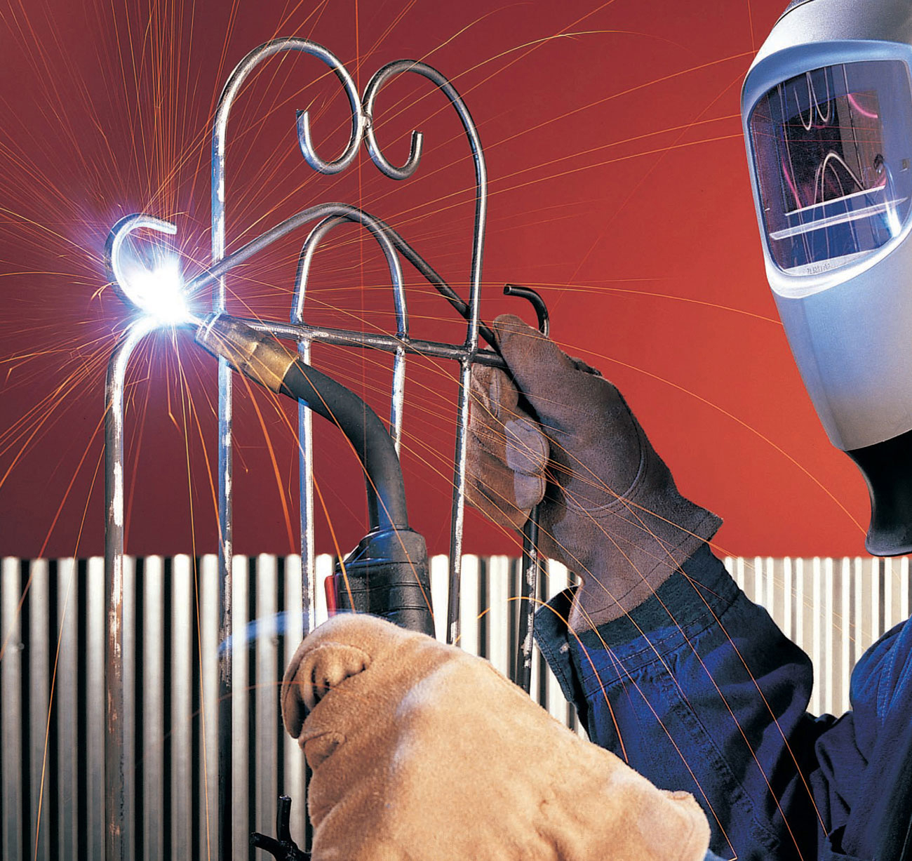
The following chapters give basic background information on the four major welding processes and two cutting processes that home hobbyists are most likely to use. Each chapter includes the equipment needed for the process and safety precautions. How-to photographs with step-by-step directions show specific techniques for each process. Tip sections offer suggestions for improving skills and keeping equipment in good condition. A separate chapter on electricity covers some basic points that are important to all of the arc processes.

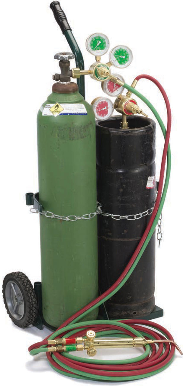
An oxyacetylene welding rig consists of two cylinders—oxygen and acetylene, regulators, hoses, and a torch with tip.
Oxyfuel welding is the process that uses the heat from a gas flame to melt base materials and cause them to join together. The gas flame is created by the combustion of oxygen and a fuel gas. Fuel gases are: acetylene, propane, butane, hydrogen, natural gas, and MPS (methyl acetylene-propa-diene, formerly known as MAPP gas). Oxygen and acetylene burn in a neutral flame at a temperature between 5600° and 6300° F, the hottest of any gas flame and capable of melting most metals. Other oxygen-fuel gas combinations are hot enough to use for soldering and brazing, but not hot enough for welding. Oxyfuel welding with acetylene is called oxyacetylene welding, but it is often simply referred to as gas welding.
The oxyacetylene process is versatile, as it can be used for both welding and cutting materials (see page 68) as well as heating, soldering, and brazing. It can be much less expensive than arc welding and is very portable because it needs no electrical power source. Oxyacetylene can be used to weld any thickness of metal, but sections over 1/4" are difficult to weld. Unfortunately, the techniques of oxyacetylene welding can be very hard to master, and there are serious safety concerns with the extreme flammability of acetylene and the high pressure gas cylinders.
Oxyacetylene welding equipment consists of an oxygen cylinder and an acetylene cylinder, each with regulators and gauges, oxygen hose, acetylene hose, torch, and tips.
Oxyacetylene welding may use fusion welding, where the base metals are melted together without filler material, or, more commonly, it may use a filler metal.
Cylinders. Oxygen comes in high pressure cylinders (sometimes called bottles or tanks) at 2200 pounds per square inch (psi) or more when full. The oxygen cylinder has a valve, and it always comes with a safety cap that screws on to the top to protect the valve. Never use the safety cap to lift an oxygen tank. The oxygen cylinder has a safety valve that will rupture to relieve tank pressure if the tank becomes overheated. Oxygen tanks should always be stored and transported in the upright position.
Acetylene. Acetylene is an extremely unstable gas. It cannot be pressurized above 15 psi in a free state. To safely pressurize the acetylene to 225 psi, the acetylene cylinder is filled with a porous material and acetone. When pressurized, the acetylene is absorbed by the acetone, which stabilizes it. When the pressure is released (the valve opened) the acetylene bubbles out of solution. Acetylene cylinders have fusible plugs that will melt in case of a fire and allow the gas to slowly escape rather than explode. Acetylene cylinders should always be stored in an upright position. Using an acetylene tank at an angle will allow acetone through the regulator and hoses, which will destroy them.
Cylinders should always be kept upright and secured with a chain or strap to prevent them from falling over. Never use a cylinder as a roller for moving heavy objects or for any purpose other than their intended use.
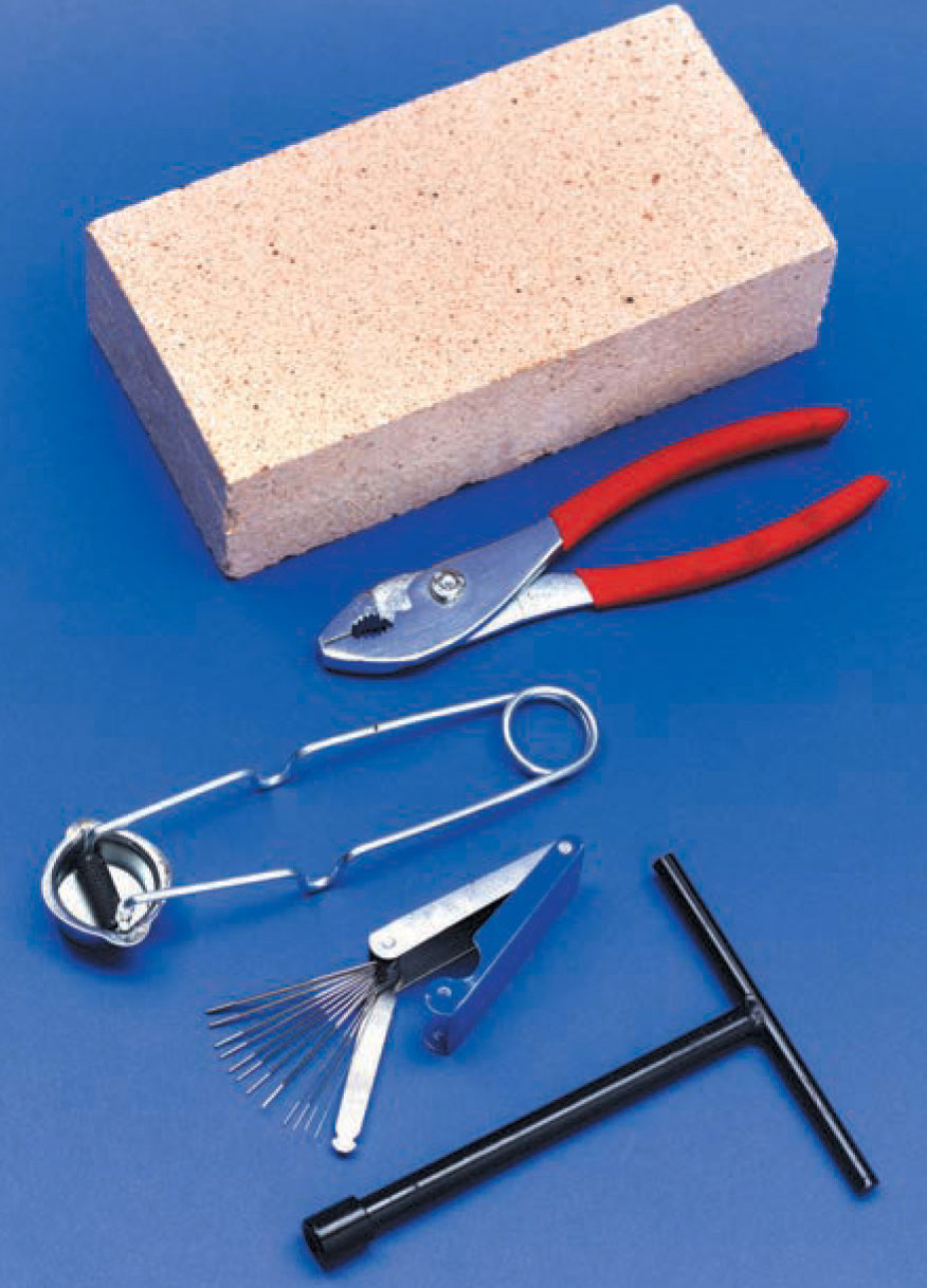
Tools for oxyacetylene welding include fire bricks, pliers, striker, tip cleaner, and acetylene tank wrench.
Cylinder Valves. Each type of cylinder has a valve that controls the flow of gas from the cylinder. A handwheel or valve wrench is used to open the valve. The oxygen cylinder valve should always be opened fully, as it is a backseating valve. A backseating valve is leakproof when closed and fully opened, but not otherwise. The acetylene valve should never be opened more than 3/4 to 1 1/2 turns. Less than this may lead to insufficient amounts of fuel and backflash; more than this makes it difficult to turn the acetylene off quickly in case of an emergency. If the acetylene valve is opened all the way, or opened suddenly, the acetone may escape from the cylinder, just like an overflowing soda can. Acetone can destroy the hoses and regulator fittings.
Pressure Regulators and Gauges. Pressure regulators reduce the pressure of the gas leaving the cylinder. A single-stage regulator reduces the cylinder pressure to working pressure in one step. A two-stage regulator reduces the cylinder pressure to working pressure in two steps. A two- stage regulator is better because it gives more precise control over gas flow. but it is substantially more expensive. The regulator adjusting screw turns clockwise to increase pressure and counterclockwise to reduce pressure. The regulator is completely off when the adjusting screw is loose or “backed out.” Always back out adjusting screws as part of your post-welding routine.
Hoses. The flexible rubber hoses that move the gas from the regulator to the torch are designed to be leakproof and withstand high pressure. The oxygen hose is green, and the acetylene or fuel hose is red. Hoses are available either as a single hose or a dual hose where the oxygen and fuel hoses are paired together. The dual hoses are more common and more convenient. Always protect hoses from damage by moving them off the floor when not in use, keeping them behind the welding area so they are not burned with sparks, and keeping them out of traffic lanes so they are not stepped on or run over by vehicles. Hoses should not be allowed to come in contact with oily surfaces and should be protected from sunlight and chemical fumes to keep them in good condition. Always drain hoses when you have finished your welding session.
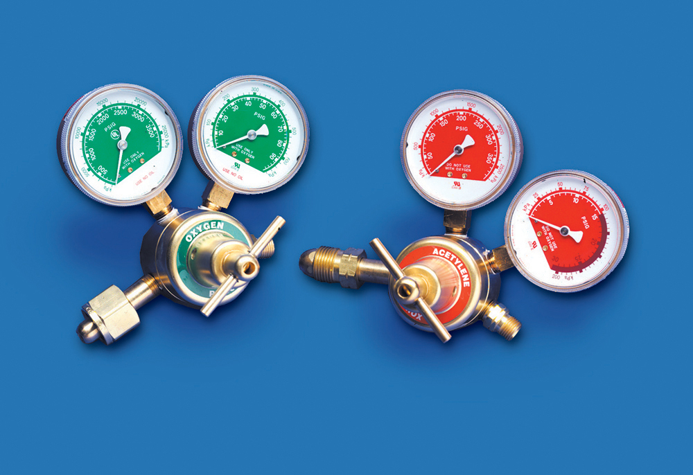
Oxygen and acetylene regulators.
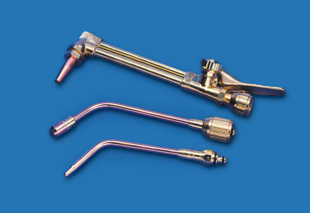
Available tips for an oxyacetylene torch body include cutting head, rosebud heating tip, and welding tip.
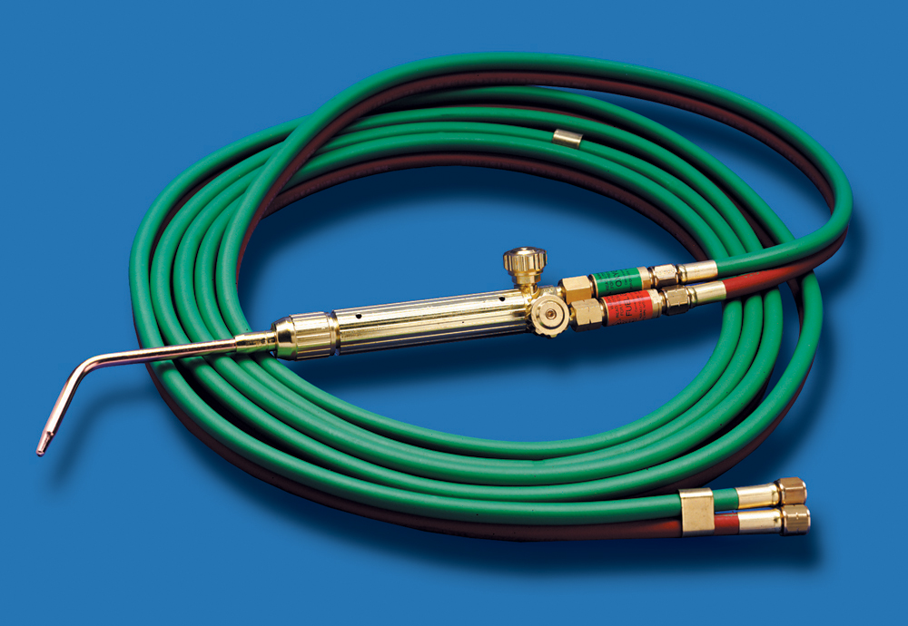
Oxygen and acetylene hoses with flashback arrestors, torch body, and welding tip.
Fittings. Fittings connect the hoses to the regulator at one end and the torch at the other. For safety, the nut for the fuel hose (red hose) is left-hand threaded and has a groove machined around the nut. The oxygen (green) hose nut is right-hand threaded and has no groove. Never interchange the oxygen and fuel hoses or fittings. Never force a fitting—brass is a very soft metal, and it is easy to damage the fitting threads. Always hand thread and hand tighten fittings before using a wrench, and be careful not to overtighten them. Never use pliers to tighten fittings, as they will damage the brass nuts.
Check Valves and Flashback Arrestors. Check valves and flashback arrestors are two safety features to prevent reverse gas flow or flashbacks. The check valve allows gas to flow from the hose to the torch. If gas pressure within the torch exceeds the hose pressure, a spring closes the valve to prevent back flow. In the event of a flashback, the check valve needs to be replaced. A flashback arrestor is installed between the torch and hose, and offers more protection than the check valve. The flashback arrestor prevents burning oxygen and fuel from flashing back into the hoses and regulator, which could cause an explosion. The flashback arrestor consists of a check valve, pressure-sensitive valve, stainless steel filter, and heat sensitive check valve. In the event of a flashback, the flashback arrestor does not need to be replaced.
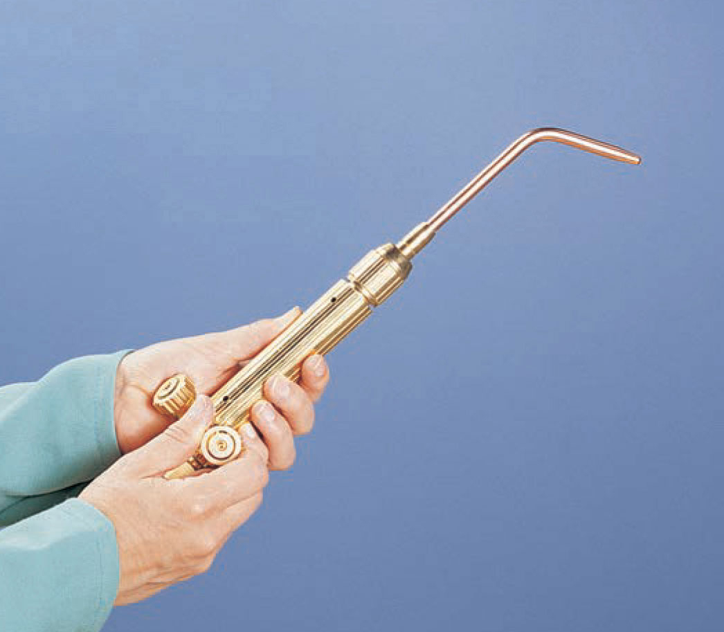
Torch. The torch mixes and controls the flow of the fuel gas and oxygen. The torch consists of valves, torch body, mixing chamber, and tips. The torch is sometimes referred to as a blowpipe, but this is not technically correct.
Tips. Tips attach to the torch body and come in many sizes to create different size flames. A cutting tip, also called a cutting head or cutting torch, is attached to the torch body to use for flame cutting. A cutting tip has a number of holes for the preheating flames around a center hole for the pure oxygen. Cutting tips also come in a variety of sizes and with different numbers of preheating holes. Heating, or rosebud, tips are used to preheat metals to improve their weldability. Welding tips come in a wide range of sizes to match the thickness of the metal being welded. Matching the tip size to the welding material and gas pressure is critical for creating quality welds.
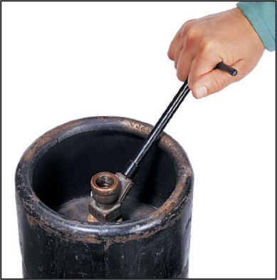
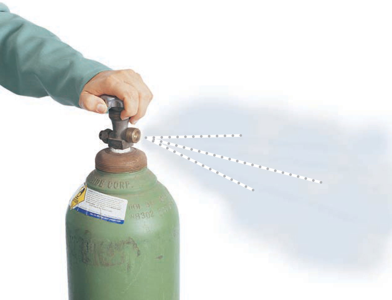
1 Secure the cylinders in an upright position, chained to a cart or strapped to a wall or post. Remove the protective cylinder caps. Wipe off the cylinder valve seats, regulator connections, and hose connections with a clean cloth. Crack open each cylinder valve briefly to expel any trapped dirt particles. “Flat top” acetylene cylinders (inset) may have antifreeze in the recessed valve seat. Use a clean rag to remove the liquid and dry the valve seat. This style acetylene cylinder requires a cylinder wrench to open the valve.
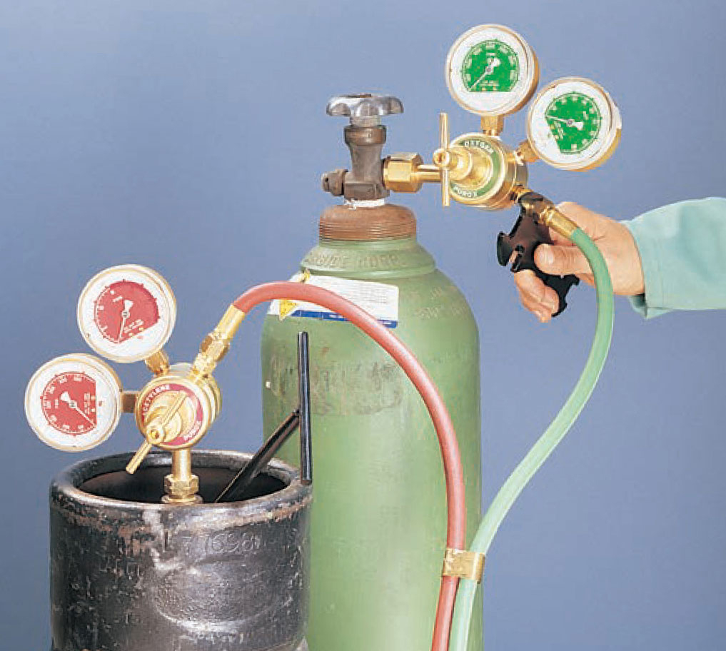
2 Attach the regulators to the cylinders. (The acetylene connectors have left-hand threads.) Always hand tighten, then use a fixed wrench, not a pliers or an adjustable wrench, to tighten. Do not overtighten—a firm seating is all that is necessary. Attach the hoses to the regulators. The acetylene hose is red and left-hand threaded. The oxygen hose is green. NEVER use grease, oil, or pipe dope to lubricate fittings. Grease and oil can ignite spontaneously when they come in contact with oxygen—even without a spark or flame present.
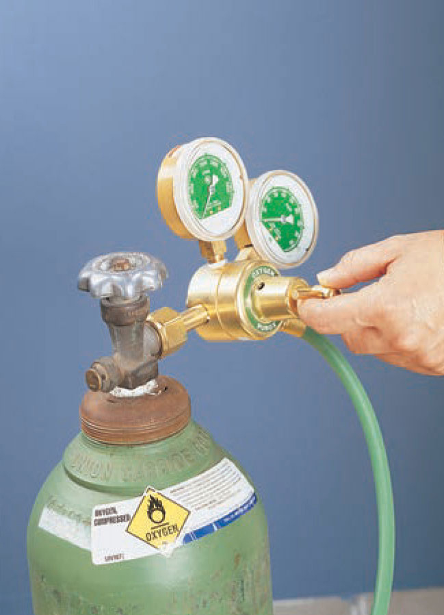
3 Turn the regulator adjustment screws on the oxygen and acetylene regulators counterclockwise until they are loose. (Some regulators may have a knob.)
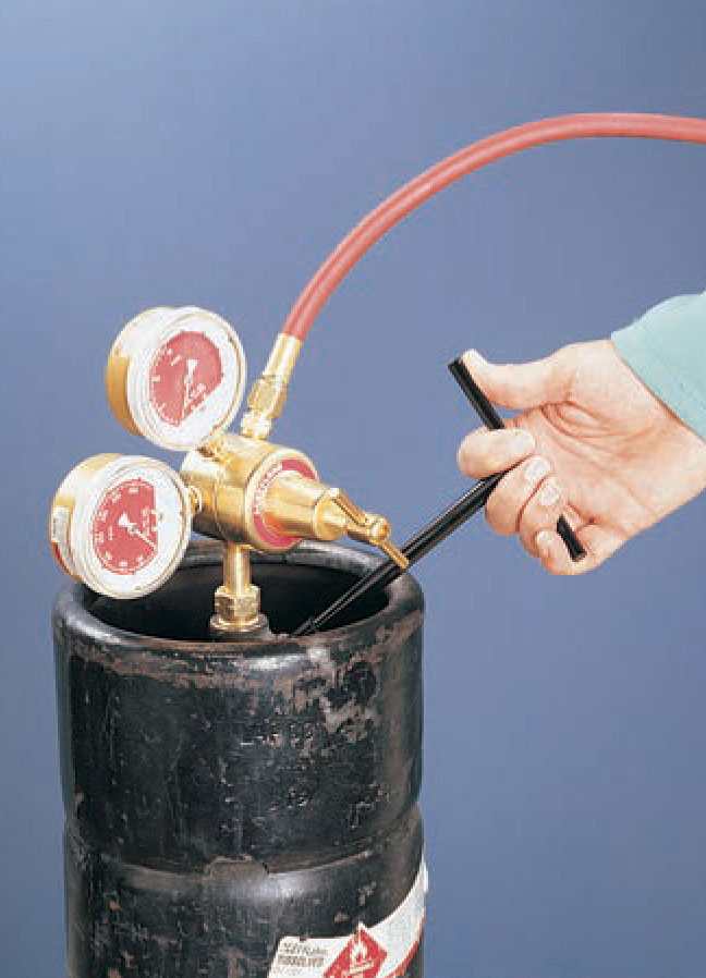
4 Open the oxygen valve slowly all the way, while standing to the side in case the regulator gauge glass shatters. Turn the regulator adjustment screw until oxygen begins to flow through the hose, then loosen the regulator adjustment screw to stop the oxygen flow. Slowly turn the acetylene cylinder valve 3/4 to 1 1/2 turns.
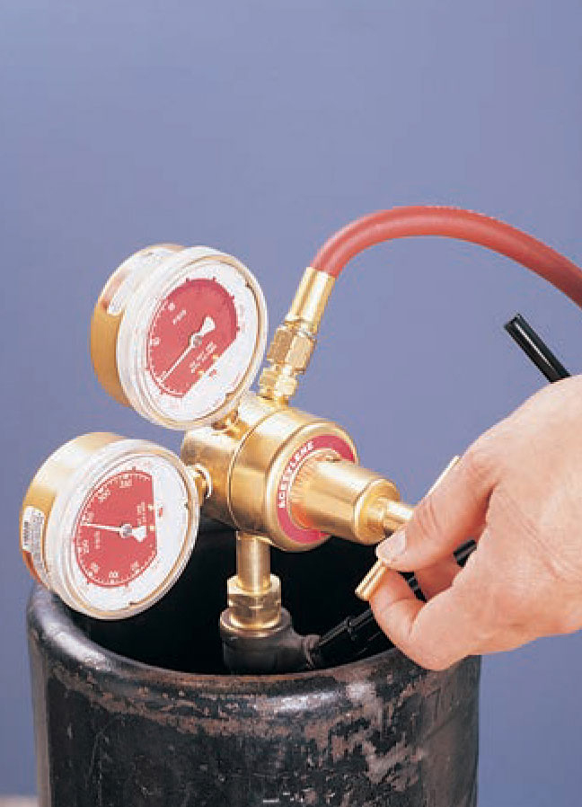
5 Adjust the acetylene regulator valve until the gas begins to flow, then loosen the regulator adjustment screw to stop the flow. Attach the torch to the hoses. Be sure to pressurize the system and check for leaks before lighting.
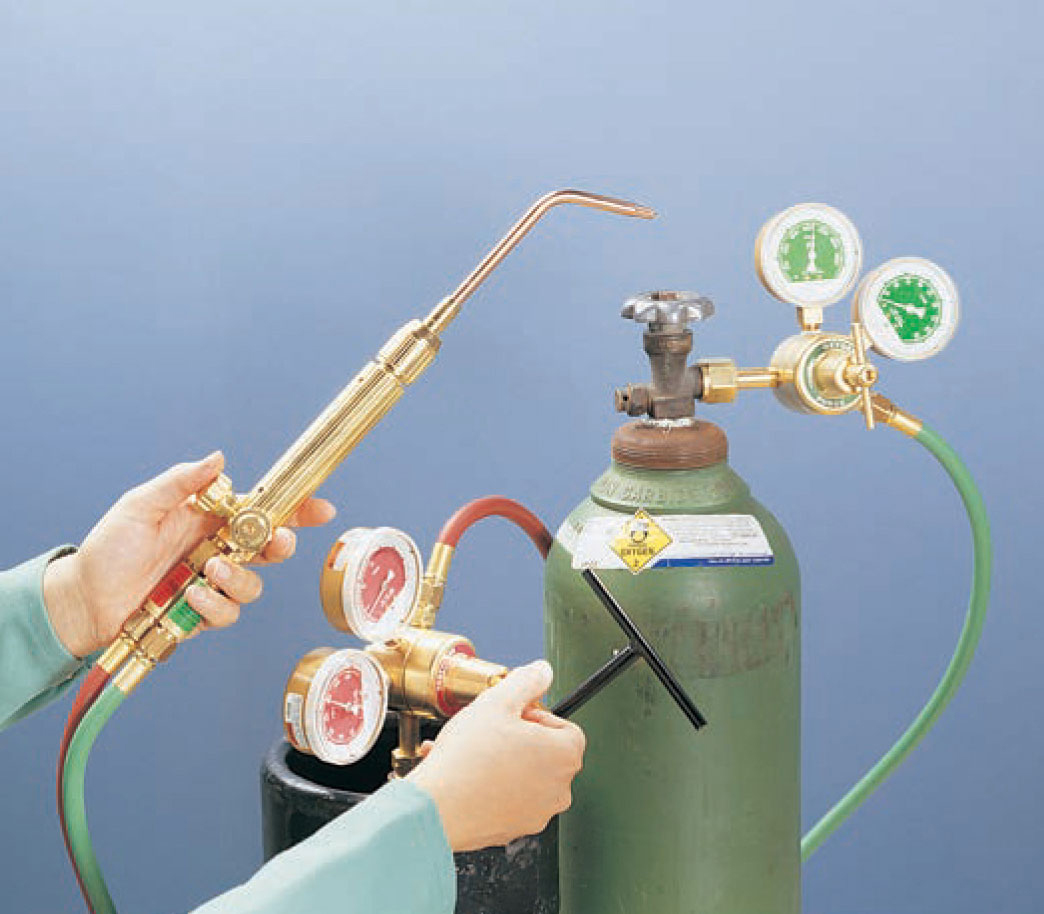
Make sure both torch valves are off. Turn both regulator adjustment screws counterclockwise until loose. Slowly turn the oxygen cylinder valve on. Once open, turn the valve all the way open to ensure proper seating without leaks. Turn the oxygen regulator adjustment screw clockwise until the gauge reads the desired pressure. (Refer to the manufacturer’s specific instructions for operating pressures.) Open the oxygen valve on the torch to check the flowing oxygen pressure. Adjust if necessary and close the torch valve. Slowly open the acetylene cylinder valve 3/3 to 11/1 turns. (Leave the wrench on the valve if it is a wrench-style valve.) Turn the acetylene regulator pressure adjustment screw until the desired pressure reads on the regulator gauge. Open the acetylene valve on the torch briefly to make sure the flowing pressure matches the desired working pressure. If not, adjust the regulator until the proper pressure is reached.
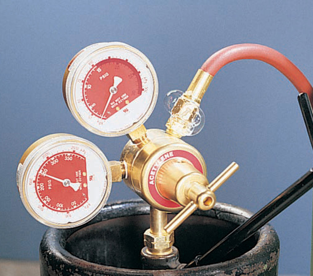
Apply leak-detecting solution to all connections with a small brush. (You can use soap and water so long as the soap is not petroleum based.) If any connections cause bubbles in the solution, tighten the connections and check again.
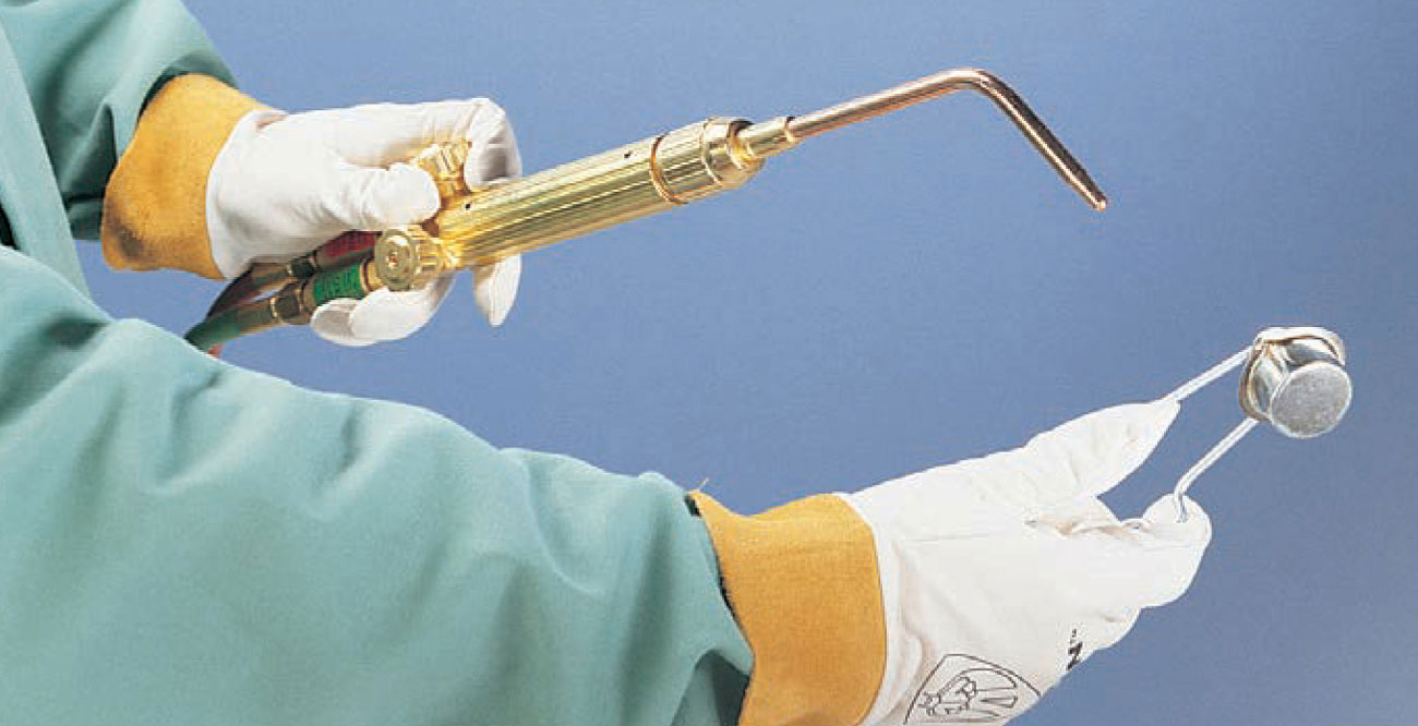
1 Hold the torch in one hand with the thumb and forefinger on the acetylene torch valve. Hold the striker in front of the torch about 3" to 6" away at a slight angle. Turn on the acetylene torch valve 1/1 to 1/1 turn.
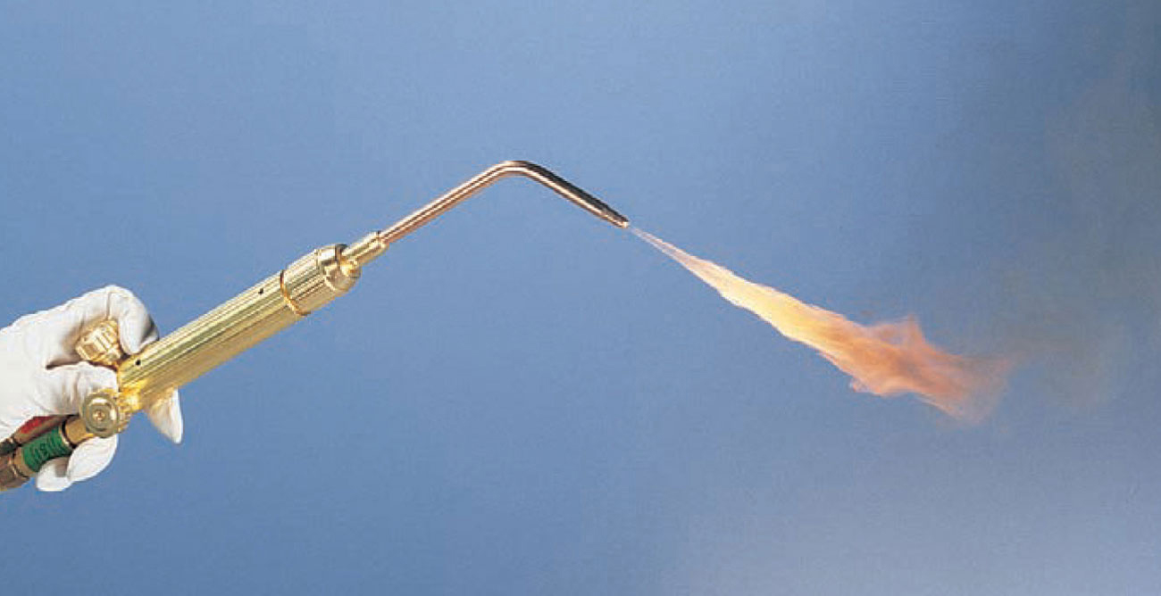
2 Immediately use the spark lighter to light the flame. The flame will be yellow and smoky.
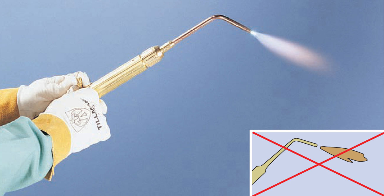
3 Put the striker down and adjust the acetylene torch valve with your right hand so the flame is burning without producing soot. The flame should not be separated from the torch (inset). Open the oxygen torch valve slowly. Adjust the oxygen to get a bright white inner flame and a bluish outer flame. Turn down the acetylene to eliminate the excess acetylene feather if present. When you have finished welding, turn off the oxygen first, then the acetylene.
The flame of an oxyacetylene torch has two parts—the inner or primary flame and the outer or secondary flame. The flame has different temperatures at different locations. The outside edges are cooler because they are burning with the ambient air, which is only 21% oxygen. The torch tip is cooler because complete combustion hasn’t been reached. The hottest area is the tip of the primary or inner flame cone. Here the gases are completely combusted and are insulated by the secondary flame. There are three flame states for the oxyacetylene flame: carburizing, neutral, and oxidizing.
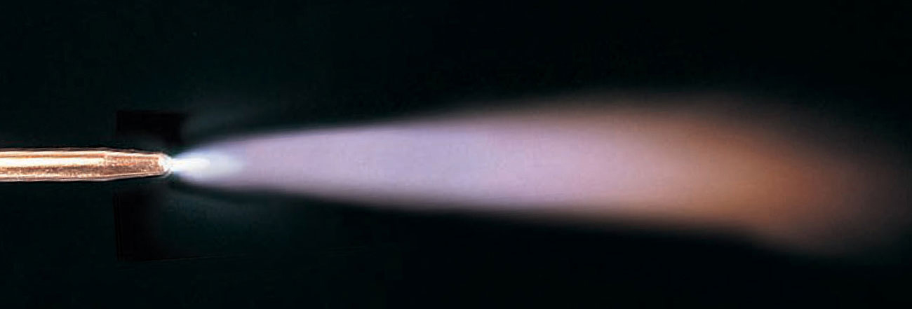
The carburizing or reducing flame has an excess of fuel. This is a useful flame as it will break down metal oxides to get at the oxygen, thus cleaning the weld area to a small degree. This process adds carbon to welds, which makes them harder. The carburizing flame has a bright white primary flame, an acetylene “feather” around the primary flame, and a bluish white secondary flame with orange edging.
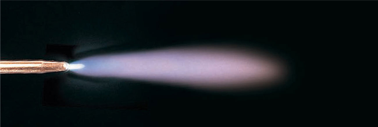
The neutral flame is the exact point where the feather and the inner cone come together. In this flame, there is exactly enough oxygen present to provide total combustion of the fuel gas. Most welding and cutting operations use a neutral flame. The neutral flame has a bright white primary flame and a colorless to bluish secondary flame.
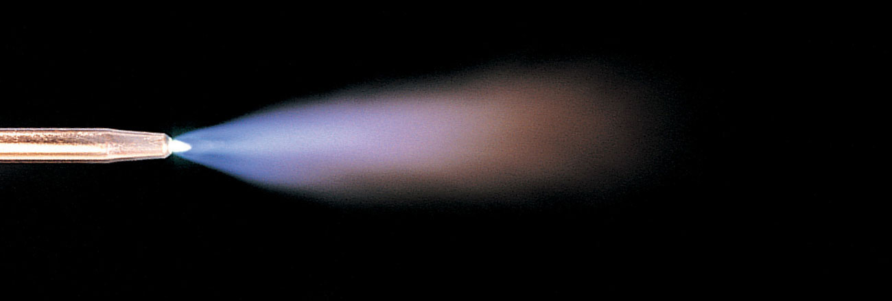
The oxidizing flame has an excess of oxygen. The white cone of this flame is small and pointed and somewhat paler than the neutral flame. A hissing sound often accompanies this flame. This flame is not particularly useful as it hastens oxidizing, which is not desirable in welding. It can, however, be used for removing carbon from molten metal, thus softening the metal.
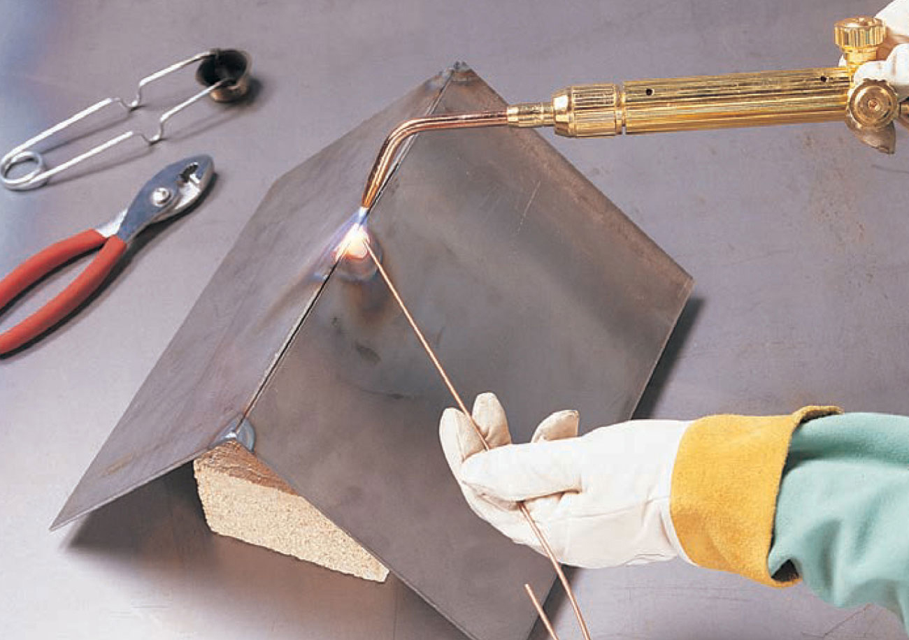
1 Select an appropriate filler rod and lay it on the table next to the bricks. Light the torch and adjust to a neutral flame. Pull down your face shield. Place small fusion tack welds at each end of the joint and in the middle if it is a long joint. (A fusion weld uses no filler rod.) Turn off the torch, oxygen first then acetylene, and check that your tacked piece is still in the desired position. If not, use a hammer to move it into position or break the tack weld and reposition.
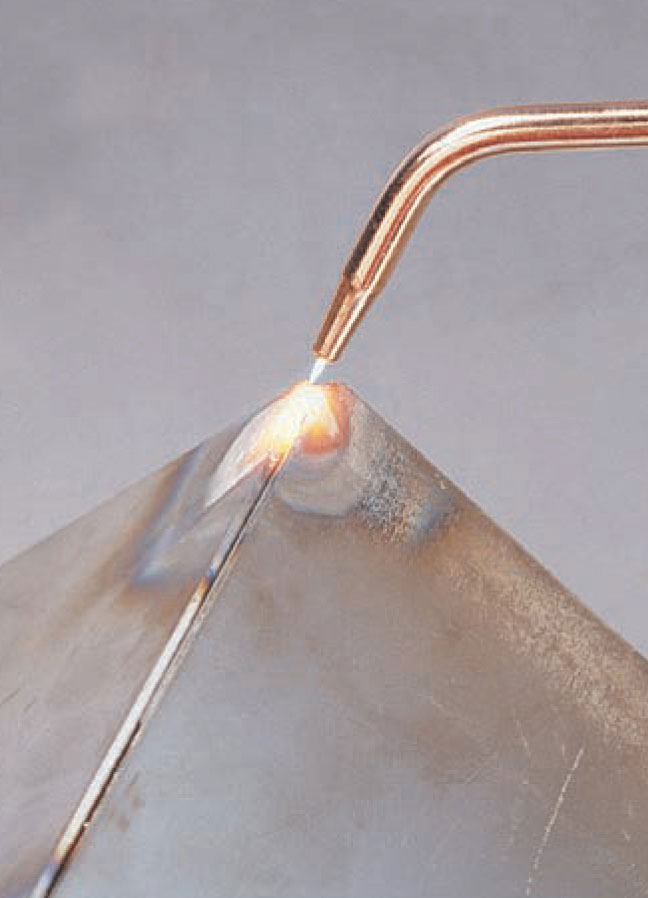
2 With the torch at a 45° angle to the right and oscillating the torch in a 1/4" to 1/2" circle over both metal pieces, create a weld puddle at the right end of your workpiece.
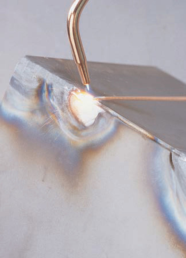
3 When a molten puddle has formed, move the filler rod close to the puddle and flame, but not in it. Begin moving slowly to the left while oscillating and maintaining the molten puddle. Dip the filler rod into the middle of the molten puddle and remove it, but keep it within the heat zone.
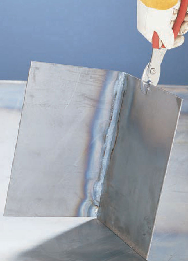
4 Continue dipping, oscillating, and moving to the left. As you reach the end of the weld, the cumulative heat build-up may make it necessary to adjust to a shallower angle to deflect heat away from the puddle and prevent burn through. When finished, turn off the oxygen torch valve first, then the acetylene torch valve. The weld should penetrate to the back without burning through.
Brazing is very similar to soldering since flux is applied to tightly fitted metal parts that are then heated to the point where filler material will melt and be drawn into the joint. Silver soldering and hard soldering are terms incorrectly used to refer to brazing. Brazing is different from soldering because it takes place at temperatures over 840° F and below the melting point of the base metals. The metals are not fused, but held together by the filler metal adhering to the base metals through capillary action.
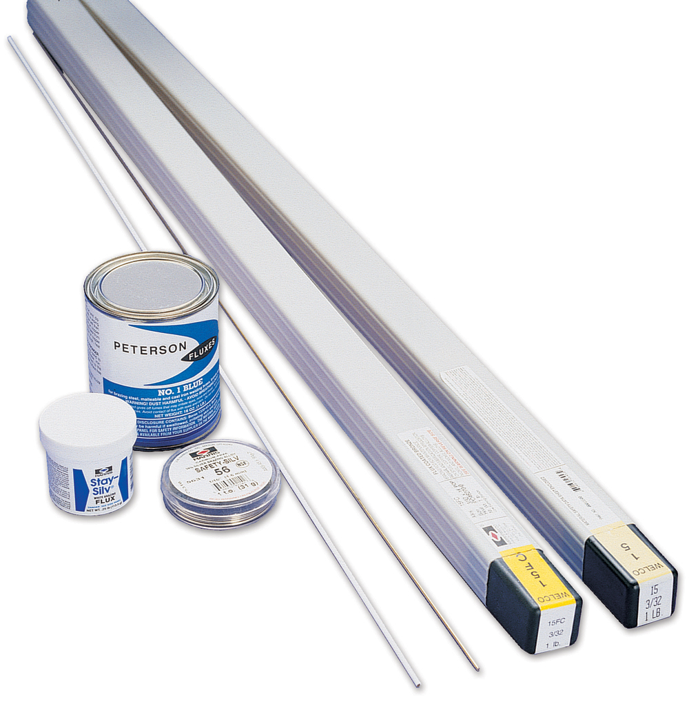
Brazing supplies include flux and silver solder (left). Braze welding requires flux coated rods, or separate flux and rods.
There are a number of industrial brazing processes, such as dip brazing, furnace brazing, and induction brazing. The home welder is likely only to do torch brazing. Torch brazing can be done with an oxyfuel torch using acetylene as the fuel gas, or any of the other fuel gases (see page 35). NOTE: Different fuel gases require different regulators, hoses, torches, and tips.
For brazing to work, the gap between the parts must be between 0.002 and 0.010 inches. If the gap is too tight, the flux and filler will not flow evenly through the joint. If the gap is too big, the strength of the joint is lessened. Gaps between parts can be measured with a feeler tool, available at automotive stores. Items to be brazed must be absolutely clean and free from rust, corrosion, grease, oil, and cleaning compound residues.
Brazing is often used commercially to join dissimilar metals such as tungsten carbide saw teeth to a steel saw blade. Another common use for brazing is in lugged bicycle frames. Because nearly every metal can be joined using brazing, it is highly suitable for art applications.
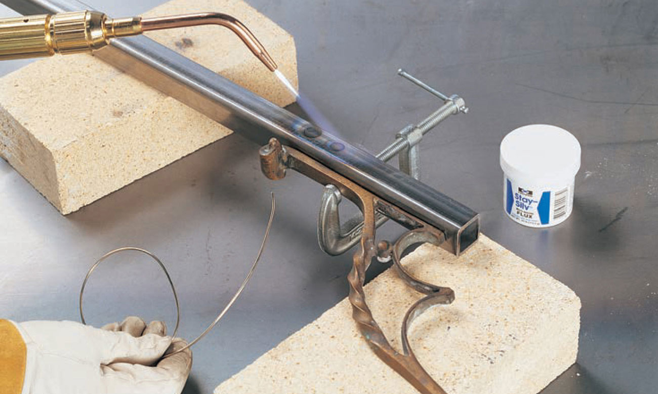
Thoroughly clean and flux both sides of the joint area. Using a small torch tip, heat the entire joint area until the flux turns clear and starts to run. Add enough filler metal to fill the joint. (Silver alloy is shown.) After the metal has cooled, the flux residue can be removed with hot water.
Braze welding is similar to standard oxyacetylene gas welding except the parent or base metals are not melted, so there is no molten puddle. Instead of a steel alloy filler rod, a flux coated brass filler rod is used. Braze welding is often incorrectly referred to as brazing. Braze welding does not use capillary action to pull filler material into the joint—the filler metal is deposited as fillet or groove welds.
The brazing rod is melted by the heat of the metal and the flame, but it should not be held in the flame itself. The parts for braze welding should fit tightly, but the gap is not as important as with brazing.
Braze welding is used for joining dissimilar metals and for metals of different thicknesses. This technique is often used to repair cracked or broken cast iron.
Braze welding has less distortion than oxyacetylene welding because less heat is applied to the parts. A disadvantage is that it is not as strong as welding where the base metal is melted, but a well-made braze weld is still sufficient for most non-structural applications. Because the base metals do not need to be melted, braze welding can be done with any of the fuel gases listed on page 35.
If you are creating a piece that will be welded and braze welded, you must be careful to complete the non-brazed welds first. The heat involved with all other welding processes will boil off the brass alloy of a braze weld, ruining the weld and creating toxic fumes.
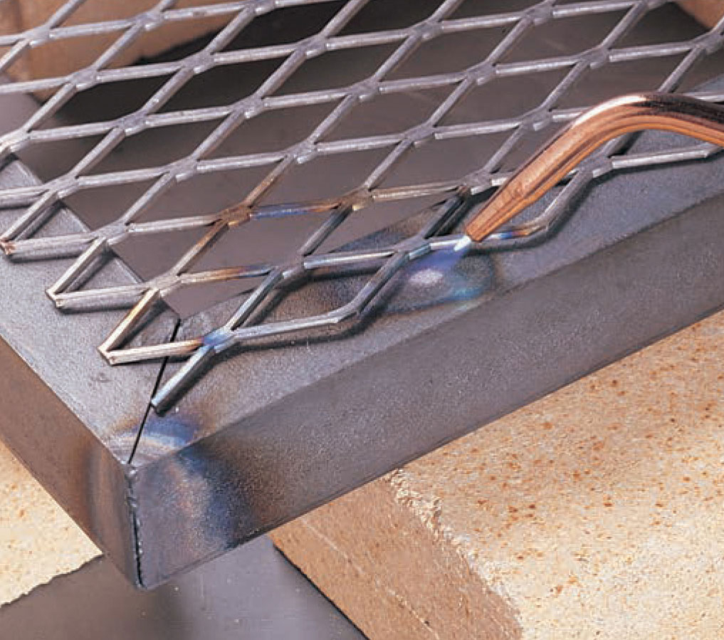
1 Braze welding is useful for joining thin metals, like this expanded metal, to thicker metals. Heat both parts, directing more heat toward the thicker part. It may take a long time for the thicker metal to heat. Using fire bricks will prevent a metal table top from absorbing any heat.
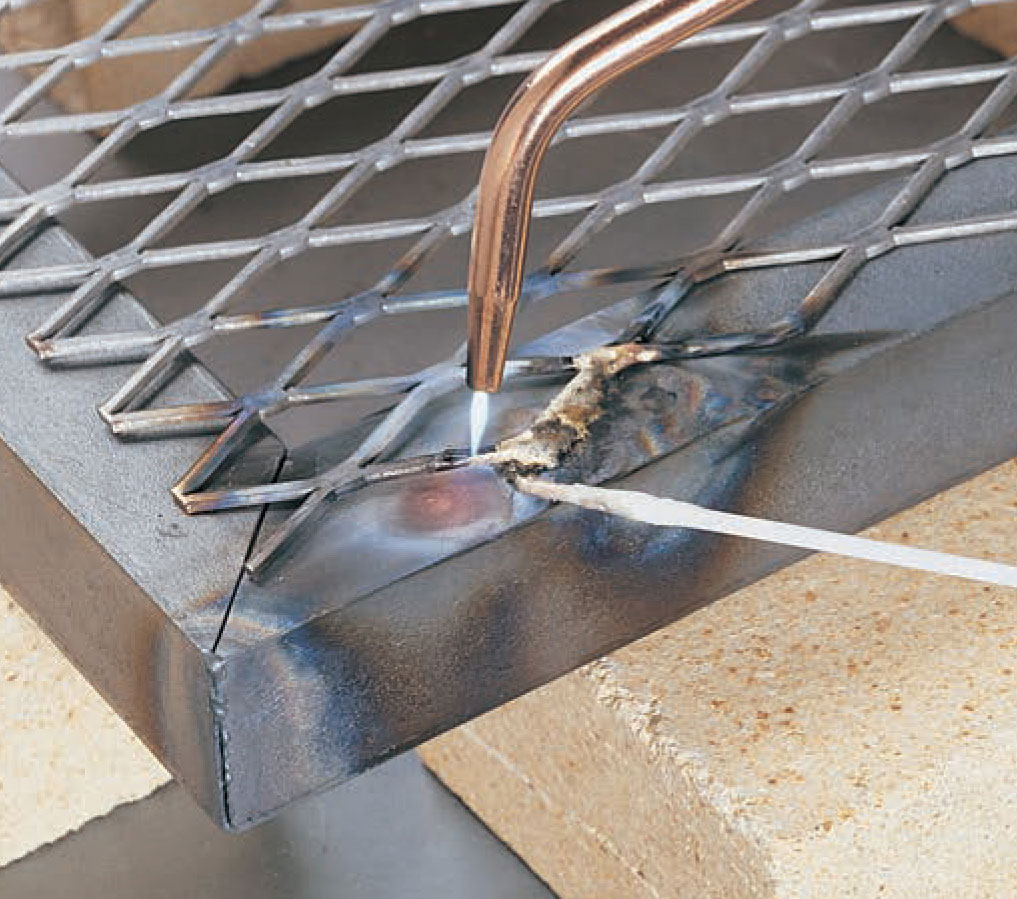
2 When both parts glow a dull cherry red, touch the flux coated rod to the joint. The flux and the filler metal will melt. If the metal is molten or the fluxed rod comes in contact with the flame, the flux will burn and the filler metal will boil. This results in a poor joint in addition to giving off toxic fumes.

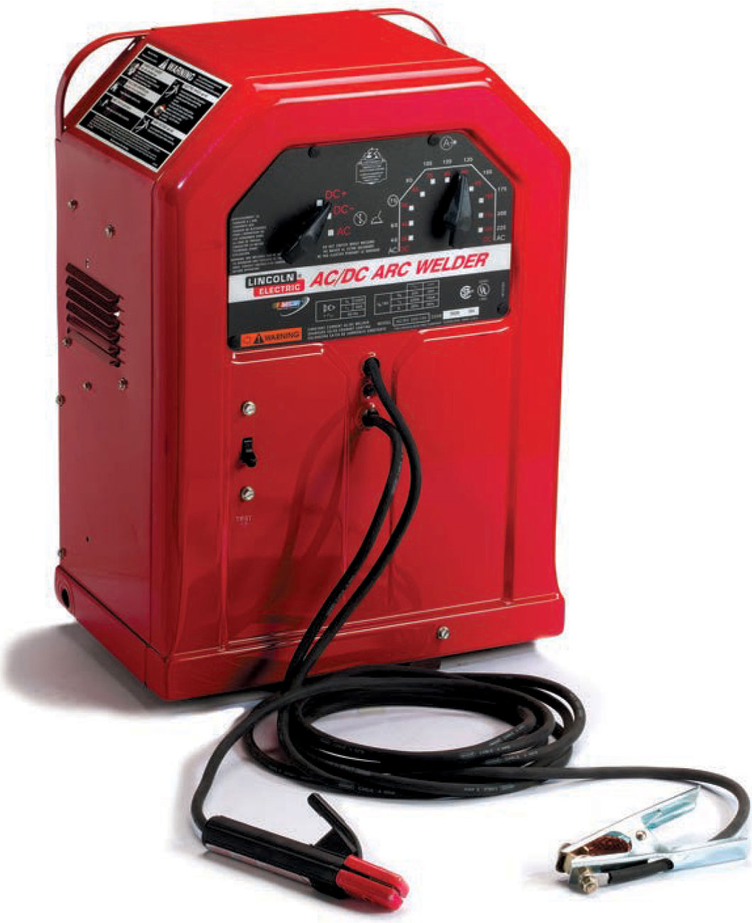
A shielded metal arc welder consists of a power source, electrode holder, and work clamp.
Shielded metal arc welding (SMAW) is also referred to as arc or stick welding. The process involves the heating of the base metal to fusion or welding temperature by an electric arc that is created between a covered metal electrode and the base metal. The coating or covering on the electrode provides both flux and shielding gas for the weld. The electrodes come in 9" to 15" straight lengths in a range of wire thicknesses from 1/1" to 3/8", hence the name “stick.” SMAW is used extensively for fabrication, construction, and repair work because the machinery is inexpensive and fairly simple, and the electrodes are inexpensive. There are drawbacks to SMAW: It doesn’t work well on thin materials (less than 1/8" is difficult), electrodes need to be changed frequently as they are used up, and the protective slag coating must be chipped off each weld.
Safety. Shielded metal arc welding uses electricity, so there is always the possibility of receiving an electric shock or being electrocuted. When an electrode (stick) is placed into the electrode holder, it is “live.” If the electrode touches anything that the work clamp is in contact with, the circuit will be completed and an arc will be struck. To prevent this from happening, always remove the electrode from the holder when you are not actively welding. Do not use your bare hands to insert or remove electrodes—always touch electrodes with dry gloves. Remember that water and electricity never mix well, so do not weld while standing on a wet or damp floor or ground, and do not weld outdoors in the rain. The electrode will be hot after use, so take care where you dispose of electrode stubs. A metal bucket is a good addition to your SMAW workshop.
SMAW welding produces ultraviolet and infrared rays, harmful fumes, and hot spatter. Protect your eyes with a #10 to #14 filter in a full-face welding helmet or hood. Heavy-duty leather welding gloves and a welding jacket with leather sleeves are necessary to protect you from the molten spatter. Proper ventilation from an exhaust hood or fan is important since many of the chemicals used in the electrode coatings are hazardous if inhaled. Also, it is a good idea to screen off your welding area so others are protected from the intense light of the arc.
The Equipment. SMAW machines are available as either alternating current (AC), direct current (DC), or with the capability of switching between the two. The machine itself is simple in that it merely converts high-voltage low-amperage line current into low-voltage high-amperage welding current. Output is controlled with one knob. You often will hear SMAW machines referred to as “buzz boxes.”
AC welding machines meet most home and small shop needs, are inexpensive, and are readily available. Because the alternating current cycles through a zero current between the positive and negative polarities, it can be difficult to strike and maintain an arc. DC machines are easier to use and have many home and hobby applications, but they are more expensive. Because DC current can have its flow reversed (see page 39), a DC machine has more versatility in terms of the electrodes that can be used. This allows for a wider range of welding positions, metal thicknesses, and metal types that can be welded. This versatility makes a DC shielded metal arc welder well worth the extra expense.
The equipment itself consists of the welding machine, which usually has one adjustment knob, an electrode lead with electrode holder (sometimes called a stinger), and a work lead with work clamp. You will often see work leads and work clamps referred to as ground leads and ground clamps. The work lead and clamp are not grounding the electricity, they are completing the circuit back to the machine.
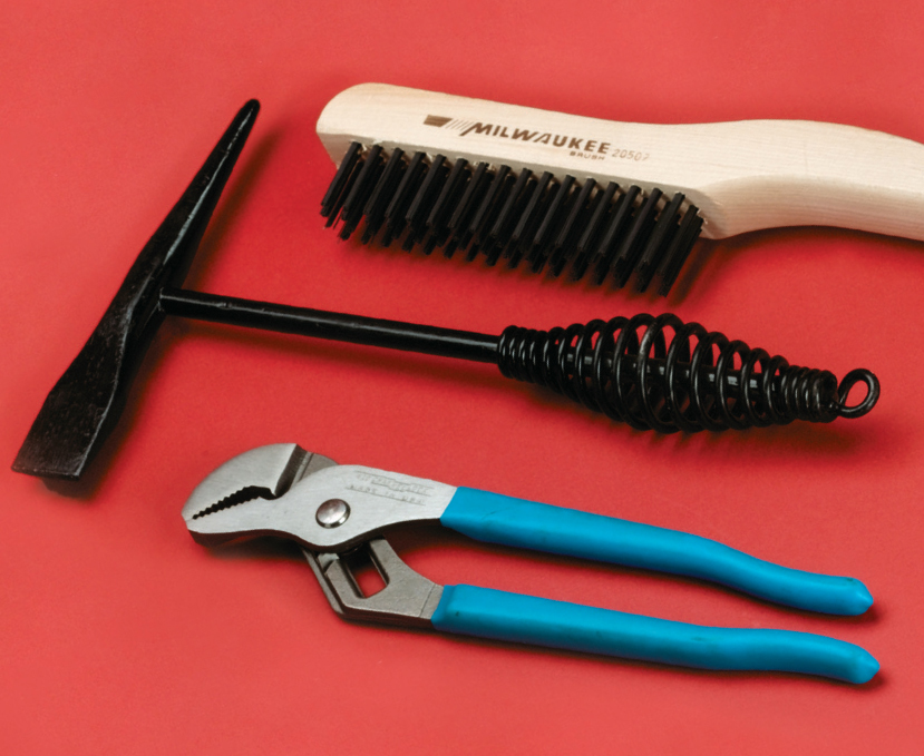
Useful tools for shielded metal arc welding are a pliers, chipping hammer, and wire brush.
SMAW Electrodes. SMAW electrodes are solid, round, metal wires coated with flux and other components. In addition to producing shielding gas and flux, the covering may also contain additional metals for filler or alloying elements for the weld.
The American Welding Society (AWS) publishes standards for the electrodes. Electrodes come in diameters ranging from 1/16" to 3/8" in increments of 1/32". The electrode diameter measures the wire itself, not the diameter of the wire with the covering. The electrode designation is inked onto the covering near the bare end of the electrode. The number classification for SMAW electrodes begins with the letter E because they are electrodes. The first two or three numbers on the left denote the tensile strength of the properly completed weld in thousands of pounds per square inch. The second number from the right indicates the welding position appropriate for that electrode: 1 = all, 2 = flat grooves and flat or horizontal fillet weld, 3 = flat only, 4 = all. The last two numbers designate the current and polarity uses and other special notes. There also may be electrode suffixes that denote alloys that have been added to the electrode.

SMAW electrodes are sold in 5- or 10-pound boxes. Specialty electrodes may be bought a pound at a time. It is important to keep electrodes dry, either in the original box or a storage container.
Each electrode manufacturer may have a number of electrodes of a specific AWS designation that are slightly different and have been tailored to specific uses. The diameter of the electrode will determine which amperage to use. Use the manufacturer’s guidelines to determine amperage. If not available, start with 90 to 120 amps minimum range for a 1/8" electrode and add 40 amps for each 1/1" increase in diameter. This will give you a rough minimum starting amperage.
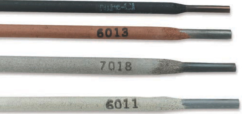
Electrodes for SMAW are stamped with a numeric code.
The most commonly used electrodes are 6011, 6013, 7014, and 7018. The 6011 and 6013 electrodes will work with AC power, the 7000 electrodes will not. For a beginner, 6013 with DC power is generally the easiest electrode to use in terms of striking an arc and maintaining a consistent arc. It is always a good idea to talk with your welding supplies dealer about what type of welder you are using, the type of welds you are making, and the materials you are working on to get the best electrode for your purposes.
Slag. Shielded metal arc welding produces a weld that is covered with a coating of ceramic-like slag. The flux and other components in the covering clean the material to be welded and also float out impurities in the weld. These impurities and flux solidify on top of the weld which protects the cooling weld from the effects of oxygen in the atmosphere. The slag must be scraped or chipped away before the weld bead is covered with another weld layer or before the weld is painted or finished. Safety glasses should be worn during this procedure.
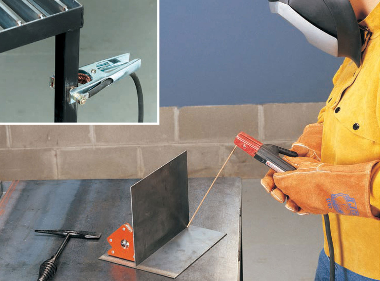
1 Set up your material to be welded. Make sure the electrode holder is not touching the workpiece or worktable. Attach the work cable clamp to the table (inset) or workpiece. Turn on machine. Adjust the range switch for the desired amperage. Wearing leather gloves, place an electrode in the electrode holder. Position the electrode over the area to be tacked, flip down your helmet, and tap or scratch the electrode on the area to be tacked to strike an arc. After making your tack welds, remove the electrode from the electrode holder. Check to see that the tacked pieces are aligned properly. If not, use a hammer to move them into alignment or break the tack welds and retack. Chip slag from tack welds so it does not contaminate the final weld.
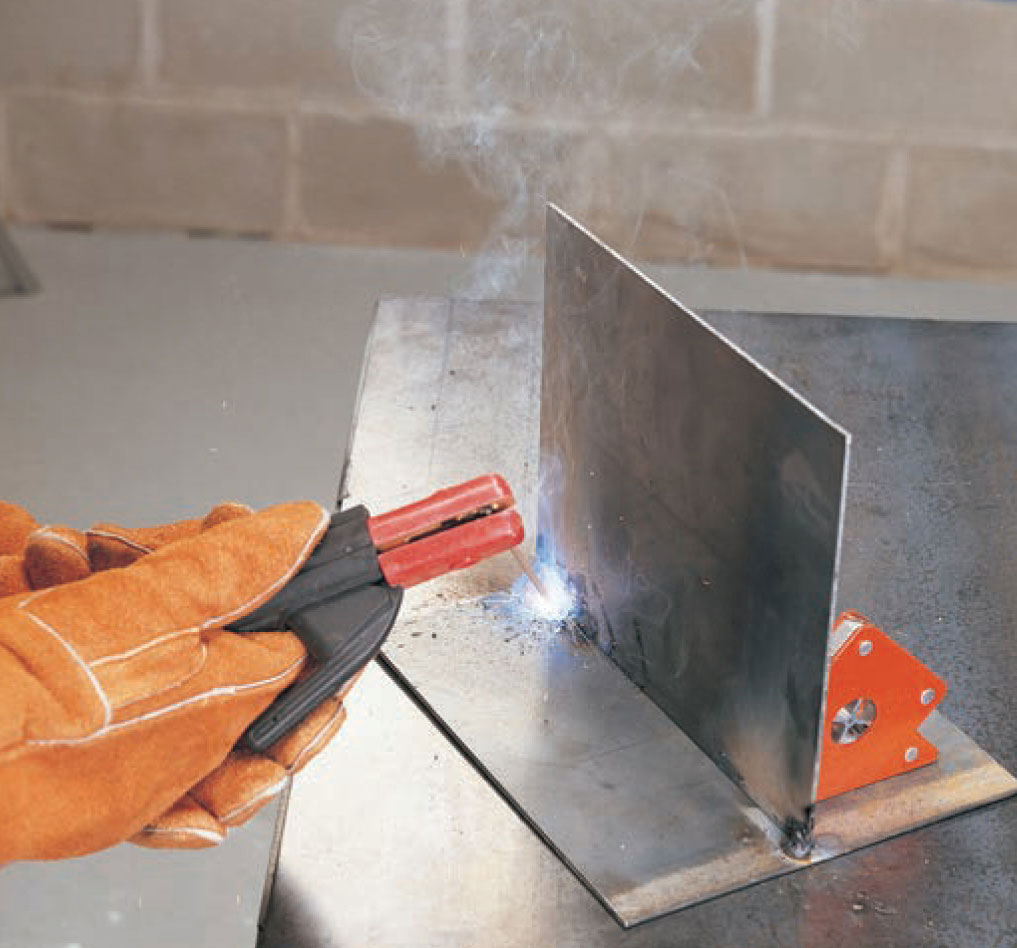
2 Replace the electrode in the electrode holder, and position the electrode over the left side of the area to be welded. Hold the electrode at a 10° to 20° angle to the right. Flip down your hood and scratch or tap to strike an arc. The distance between the metal and electrode should not exceed the thickness of the electrode bare wire diameter. Move slowly to the right until the weld is completed.
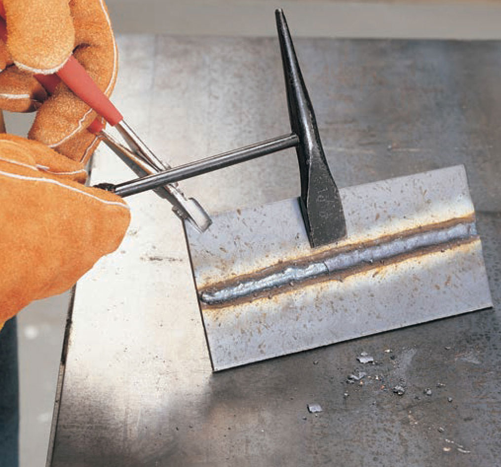
3 To remove slag, hold the workpiece with pliers at an angle and scrape or knock the slag with the flat blade of the chipping hammer. Wear safety glasses when chipping slag.


A gas metal arc welding setup consists of a power source, wire feed, work cable with clamp, supply cable with gun, and gas cylinder with regulator.
Gas metal arc welding (GMAW), also referred to as MIG (metal inert gas) or wire feed, is a process where a consumable electrode (wire) is automatically fed through a welding gun along with a continuous flow of a shielding gas. The actual application of filler metal is achieved with most small machines through the short circuit transfer method. Other transfer methods used by more powerful machines are short circuit globular and spray pulse.
The GMAW process has a number of advantages. The gun or torch can be held at a uniform distance from the weld, unlike shielded metal arc welding where the distance from the electrode holder to the weld becomes shorter as the electrode is consumed. The trigger power control on the welding gun also makes it possible to be completely positioned and ready to weld without accidentally striking an arc. When ready to weld, the welder can flip down the helmet and pull the trigger without getting off target. Because the electrode is the filler, the welder does not need to coordinate a filler rod in one hand and the torch in the other. The GMAW gun can be held steady with both hands to create a uniform bead. Because of the shielding gas, GMAW welds are smooth and clean, with no slag to chip or grind. The GMAW process can operate at very low amperages and is a relatively cool welding process, so 22 and 24 gauge sheet metals can be welded without distortion. The process also requires narrower beveling for thicker plate welds, so less time is spent on grinding.
Some disadvantages of GMAW are that the shielding gas nozzle does not allow for welding in tight spaces without some modifications. Because the shielding gas can be disrupted or blown away by drafts easily, the process is not suited for working outdoors.
Power supply. In the small GMAW units, the power supply and wire feed are integrated into the same cabinet. In larger, multipurpose machines, the wire feed is a separate unit. The power supply converts the standard alternating current (AC) into direct current (DC). Alternating current is not appropriate for gas metal arc welding because its constantly switching flow does not yield a steady, consistent arc. On the machine, you will be able to adjust the voltage, polarity, and wire feed rate; the machine adjusts the amperage. When using the power source to weld with a shielding gas, the machine should generally be set up for electrode positive, that is, the electrode is positive and the workpiece is negative. If used without shielding gas and with flux cored wire, the polarity usually needs to be switched to electrode negative. This is achieved by switching the contact wires within the machine. Larger, multipurpose machines may have a switch to change the polarity. Always check manufacturer’s recommendations for polarity settings.
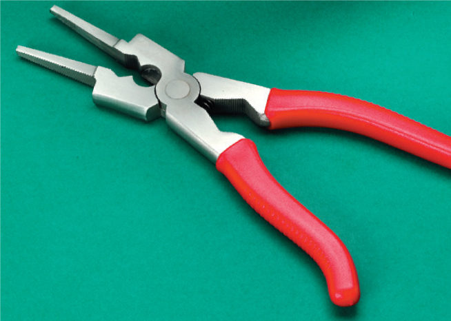
A MIG pliers is a handy tool for gas metal arc welding.
Wire feed. The wire feed consists of a spool of wire, a tension controller, and rollers and a roller motor. The wire speed is set by the speed adjustment knob, depending on the thickness of the material being welded. The rollers have V or U grooves sized to match particular wires. Most machines come with two-sided rollers that can be switched over to handle two different size wires.
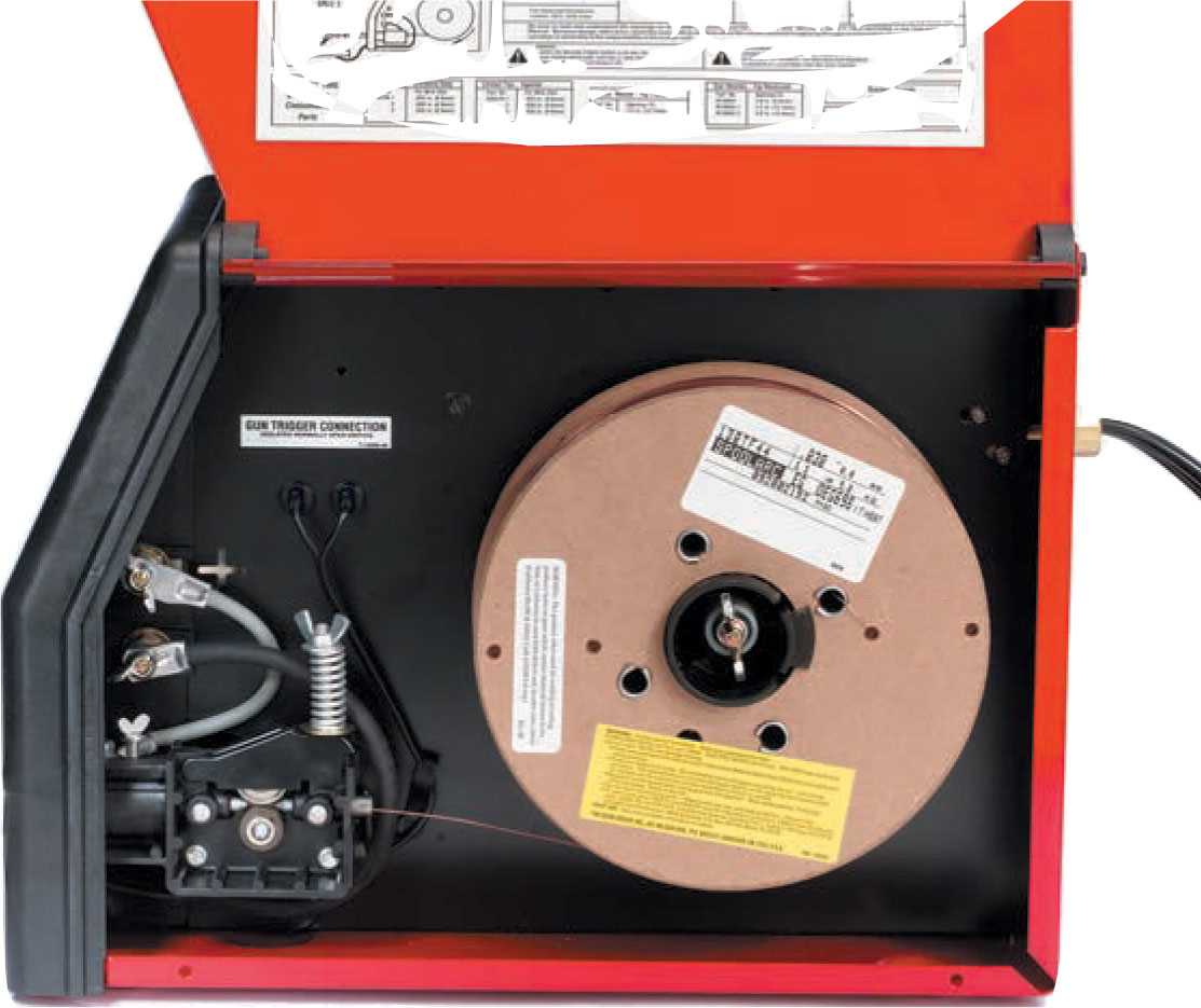
The wire feeding mechanism consists of a spindle to hold the wire spool, drive wheels, rollers, and a tension adjustment. Most welders now have a reference chart with recommended settings.
Gun. The GMAW gun, sometimes referred to as a torch, is attached to the welding machine via the supply cable. The cable carries the power, the power control, the wire in a special liner, and the shielding gas. The gun has a trigger that turns the power on and off, which also starts the wire feed and the shielding gas flow. The gun generally has a goose neck shape, although straight neck and flexible neck guns are available. A contact tip is screwed or cam locked into the gun. This tip has an orifice the same size as the wire being used. It is important that this be sized correctly—too large and good electrical contact between the source and the electrode will not be made, too small and the wire will not fit. The shielding gas is directed toward the work area with a nozzle. On most home versions, the relationship between the contact tip and the gas nozzle stickout is not adjustable; larger welders have a wider variety of nozzle sizes and shapes. It may be worthwhile to purchase an aftermarket adjustable system. When using the GMAW process, it is important that the supply cable be kept as straight as possible to prevent kinking the wire or impeding the gas flow.
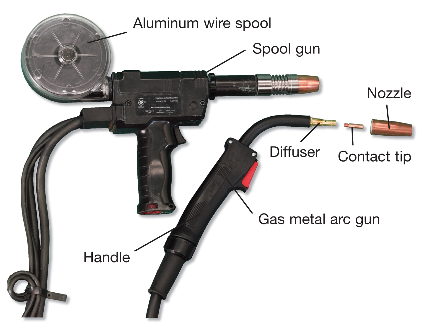
A spool gun is used for feeding aluminum wire because it often breaks or misfeeds through a standard cable. A standard gas metal arc gun consists of a handle, gas diffuser, contact tip, and nozzle.
The final piece of equipment is the work cable with clamp. This is clamped to the workpiece or to a metal work surface that the piece sits on to complete the circuit.
Electrodes. When choosing an electrode (wire), consider the composition properties, cleanliness of the base metal, and the shielding gas. If you will be welding out of position, this will also be a factor. There are dozens of wire choices for GMAW.
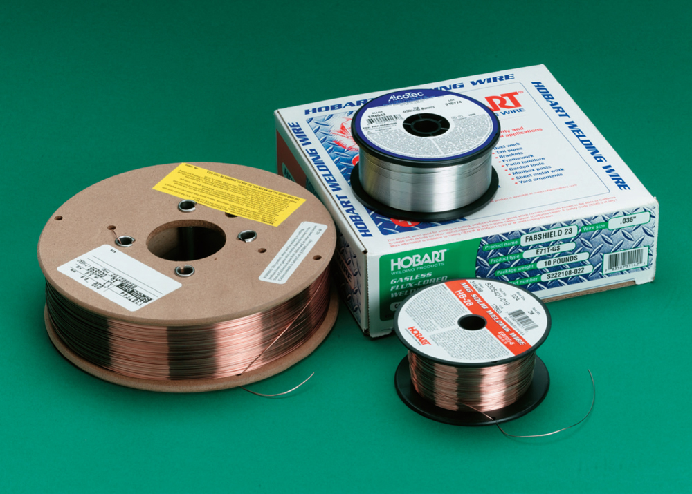
Most home GMAW welders use 1-pound or 10-pound wire spools. Larger spools are generally less expensive.
Electrodes are labeled with alpha-numeric codes that describe their type, tensile strength of the weld, whether it is solid or tubular (tubular is flux cored), and chemical composition. For mild steel, ER70S-3 is a good general purpose wire. ER70S-4 and ER70S-6 are good wires for dirty or rusty metals. Wire also is available for welding aluminum and stainless steel. Available wire sizes are 0.024, 0.030, 0.035, and 0.045 inches.
Using a wire feed machine without shielding gas requires the use of flux cored wire (often called innershield), and the process is then called flux cored arc welding (FCAW). Because the wire makes the electrical contact as it travels through the contact tip, the flux must be inside the wire, which makes flux cored wire more expensive than regular GMAW wire. Commercial welders may use a “dual shield” flux cored wire that does use a shielding gas. Welds made with this process are as clean as regular GMAW welds.
Flux cored arc welding can be done outdoors because there is no shielding gas to be disturbed by wind and weather. Unfortunately, using flux cored wire results in a less attractive weld due to the presence of slag and more spatter. The flux cored wire usually has greater penetration and is often used to stretch the capabilities of a small welding machine. Because 0.035" is the smallest diameter for flux cored wire, it is not appropriate for welding thin sheet metal. The lowest setting for this size wire is still too hot for this application.
Shielding Gas. The shielding gas for GMAW is supplied by a cylinder with a flow regulator and connecting hoses. The gas line is connected to the welding machine, which directs it through the cable.
Carbon dioxide is suitable for general GMAW welding. It gives good penetration and is inexpensive compared to other gases. Argon and carbon dioxide in a 75% argon and 25% carbon dioxide mix is the standard GMAW shielding gas. It is slightly more expensive than pure carbon dioxide, but it yields welds with less spatter. Pure argon is used for shielding aluminum welds. If you choose to use pure carbon dioxide, select an electrode that performs well with this shielding gas.

A flow meter registers gas flow with a small floating ball.
Gas Cylinder Safety. Gas cylinders store compressed gases at pressures up to and greater than 2000 psi. This is sufficient pressure to send a tank through a concrete wall if the cylinder valve should be damaged. It is important to be extremely careful with gas cylinders even when they hold the non-flammable gases used in GMAW welding. Gas cylinders should always be upright and chained or strapped to a wall, post, or cart. Never drag a cylinder; never lay one down or roll it flat. To move a cylinder, chain it to a handcart first. If you must move a cylinder without a handcart, tip it slightly and roll it. Never weld anything to the cylinder or safety cap—and be careful to never accidentally strike an arc against a cylinder. If you do, you will have to purchase that cylinder.

1 Contact tubes are stamped with their size. Make sure the contact tube and the drive roll grooves are the correct size for the electrode you are using. Place the wire spool on the spindle, and secure it with the pin lock, lock ring, or wing nut. Make sure it is feeding in the proper direction.
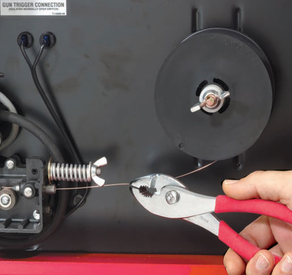
2 After releasing and cutting off the crimped wire end, hold the wire firmly with a pliers. The wire is tensioned and the entire spool will rapidly unroll if you do not hold it firmly. Swing the tension arm or pressure roll out of the way. Push the wire through the inlet wire guide, through the groove on the drive roll, and out through the outlet wire guide.
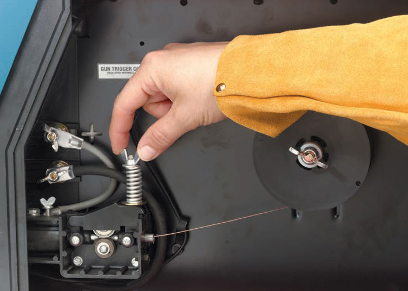
3 Swing the tension arm or pressure roll back into position. Adjust tension according to manufacturer’s directions. On a new machine, the drive roll pressure will already be set. Make sure the wire is aligned perfectly straight—not up and down or side to side—on the drive roll. Turn the machine on, turn the wire speed to its highest setting, pull the cable straight, and depress the trigger. Some machines have an inch button that feeds the wire without supplying power to the contact tip or wasting shielding gas while loading wire.
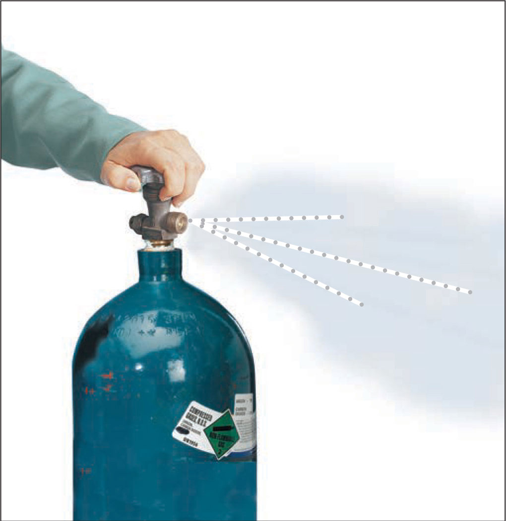
1 Open the cylinder valve briefly to clear out any dirt. Wipe the cylinder threads with a clean, dry cloth.
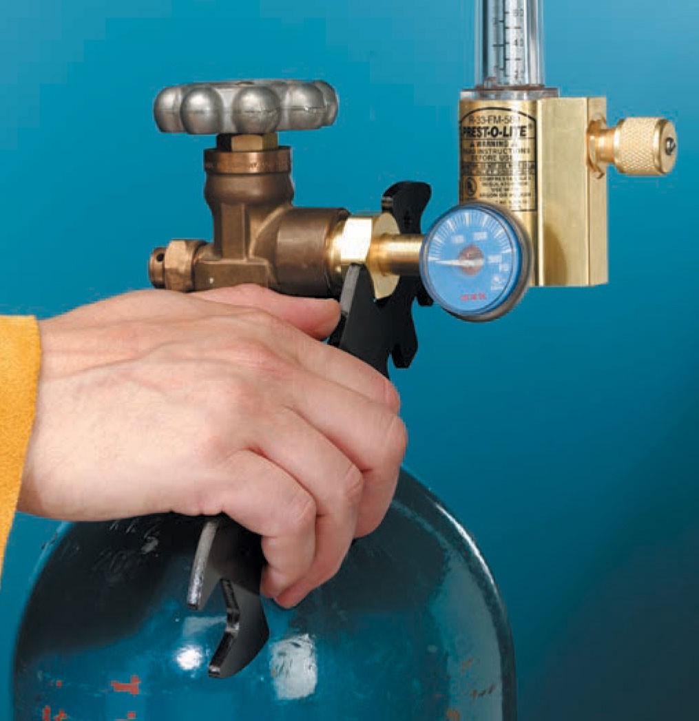
2 Attach the flow meter to the cylinder. Use a fixed wrench to prevent damaging the brass fittings.
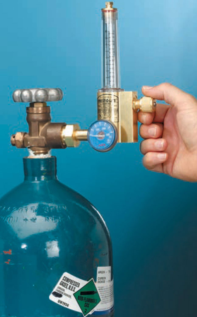
3 Turn the knob on the flow meter clockwise to tighten it so no gas can flow through it. If the flow meter is open when you open the cylinder valve, the high pressure can damage the flow meter.

4 Attach the hose to the flow meter and to the welding machine. Slowly open the cylinder valve, then, once it is open, open the cylinder valve completely. To set the flow rate, turn on the machine. Depress the trigger to activate the gas flow, and turn the flow meter knob counterclockwise. While gas is flowing, continue turning the knob until the meter registers the proper flow rate. Make sure that the flow meter or flow gauge is rated for use with the shielding gas you are using. For example, an argon/carbon dioxide flow meter cannot handle pure carbon dioxide.
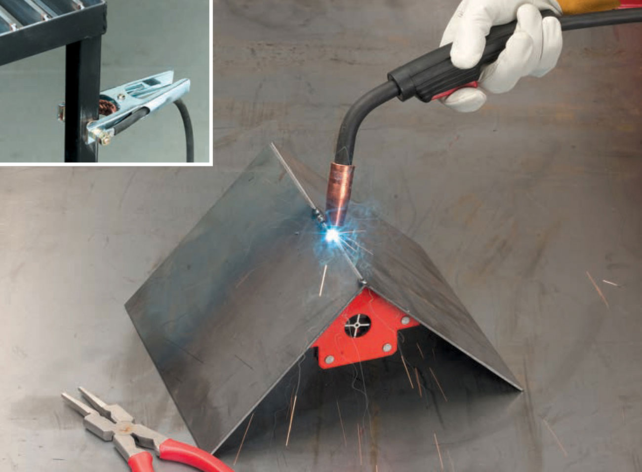
1 Prepare and fit up the material to be welded. Attach the work cable clamp to your welding table (inset) or the workpiece. Turn on the machine and shielding gas. Adjust the wire speed and voltage according to the manufacturer’s recommendations. Cut the electrode to 3/3" stickout. Put the tip of the electrode at the point of the first tack weld, flip down your helmet, and pull the trigger. Place tack welds evenly around the weld area. Trim the electrode for proper stickout at the end of each use. Check to see that the workpiece is still aligned properly. If not, adjust with a hammer or break the tack welds and retack.
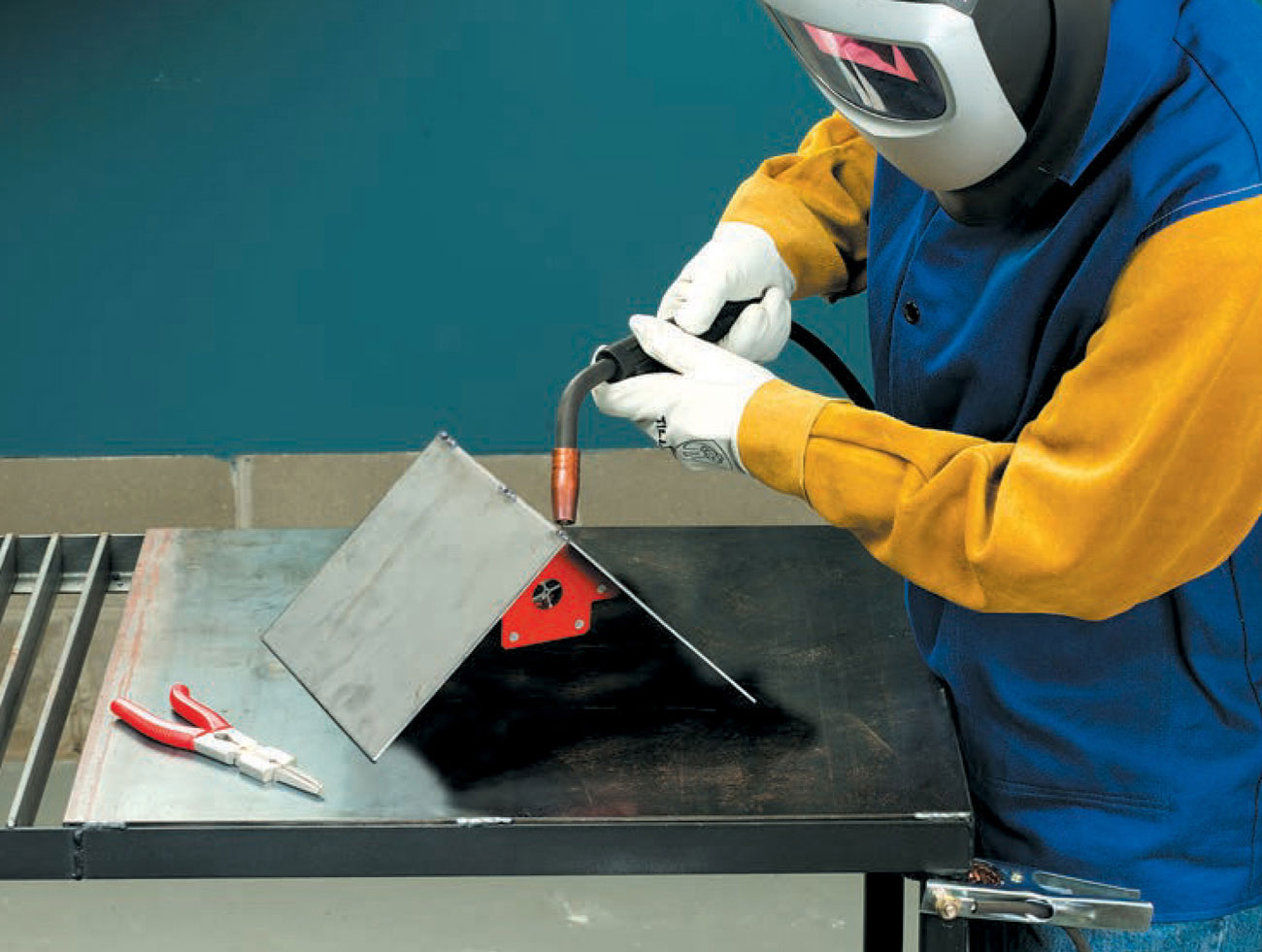
2 Start at the left end of the weld. Hold the gun with both hands and position it at a 20° angle with the tip pointing to the left. Put the tip of the electrode at the beginning of the weld, flip down your helmet, and pull the trigger.
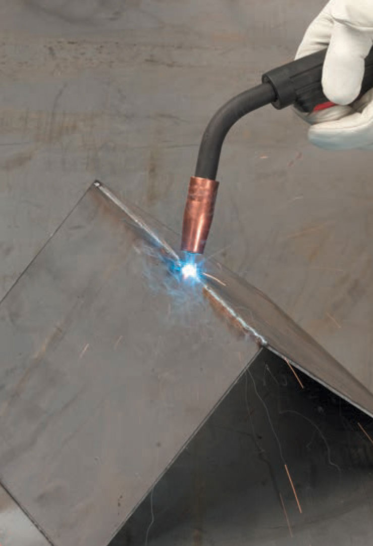
3 Begin welding, moving steadily to the right. GMAW has a distinctive sizzling sound. Popping and snapping indicate dirty material or an improper voltage or wire speed adjustment.
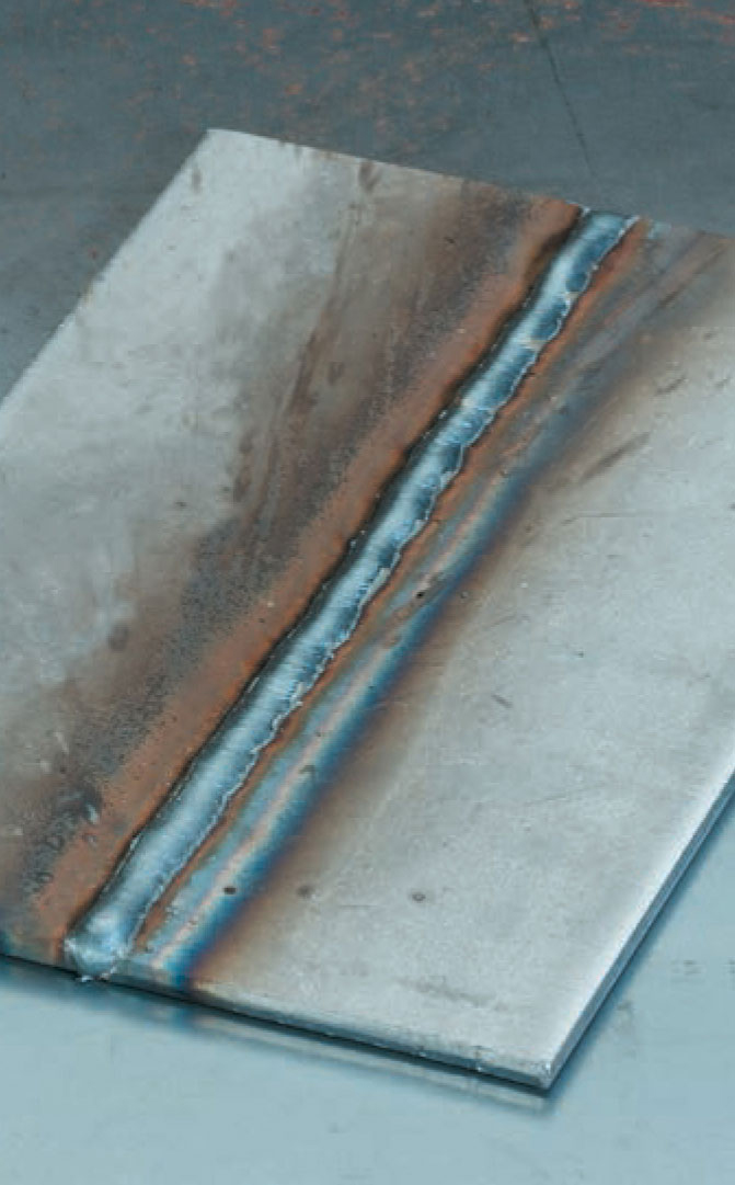
4 A finished GMAW is smooth with even ripples or weave pattern, no slag, and little spatter.
A small amount of maintenance on your GMAW equipment will result in better, more consistent welds and longer lasting equipment. Spatter—tiny pieces of the electrode or base metal that have sizzled off—builds up on the nozzle and the contact tip. Remove this spatter frequently as you weld so it does not interfere with gas flow or electrical conductivity. Turn off the machine, remove the nozzle, and use the closed point of the MIG pliers (page 45) to ream out the nozzle and file the end of the contact tip. An anti-spatter gel is available in which to dip the hot nozzle and contact tip. Anti-spatter spray can be used to coat the contact tip and the nozzle. This spray is also useful for coating your welding table to prevent spatter from sticking to your work surface. Eventually you will need to replace the nozzle, but regular maintenance and proper welding techniques will extend the life of a nozzle considerably.
Contact tubes become worn because they are a soft copper alloy and the electrode is steel. The electrode will wear through the contact tip, possibly making the electrical flow irregular. Contact tips should be visually inspected for wear on a regular basis. The orifice on a worn contact tip will appear oval instead of round. Tips generally are good for about eight hours of continuous welding use. NOTE: Always turn off the welder before changing the contact tip.
It is important to keep the welder fan motor and rectifier free of dirt and dust to prevent it from overheating. If your welder is stored in a dusty shop, or you use it infrequently, keep it covered. Use low pressure air to blow dust and dirt from these assemblies. Use a vacuum to remove dirt from the wire feed mechanism.
The supply cable needs to be cleaned occasionally as well. Check the manufacturer’s recommendations for frequency, but they generally recommend cleaning after you’ve used 50 pounds of flux cored wire or 300 pounds of solid wire. With the power off, remove the cable from the machine. Remove the gas nozzle and contact tip from the gun, lay out the cable straight, and use low pressure air to blow into the gun end. (Using high pressure air may create a dirt plug that will clog the cable permanently.)
Always store the supply and work cables and the gas hose off the floor and away from chemicals, hot sparks, and sunlight.
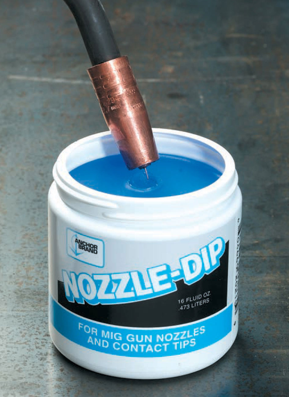
Use dippable anti-spatter gel to prevent spatter build up on the nozzle and contact tip. Simply dip the hot nozzle into the gel.
“Stub out” is when the electrode welds to the base metal without melting or breaking off. This is caused by the voltage being too low, the wire feed being set too fast, or holding the gun too close to the work when starting. Correct the settings, grind off the stub outs, and restart the weld.
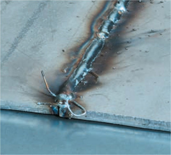
Stub out results in short sections of wire poking out of the weld.

A gas tungsten arc welding setup consists of a power source, work cable and clamp, supply cable and torch, foot control, and gas cylinder with regulator.
Gas tungsten arc welding (GTAW), commonly called TIG (tungsten inert gas), and sometimes referred to as Heliarc (the L-TECH trade name), is a process that generates an arc between a non-consumable tungsten electrode and the work-piece. The electrode and the weld are protected by a shielding gas, and filler metal may or may not be used.
Gas tungsten arc welding differs from the other arc welding processes because the electrode is non-consumable and not used as filler material. GTAW is more like oxyfuel welding in terms of the skills needed to manipulate the torch with one hand and the filler rod with the other. GTAW requires another layer of coordination because most machines also use a foot activated amperage control.
Like gas metal arc welding, gas tungsten arc welding is a clean process because the shielding gas eliminates the need for flux and the resultant slag.
Safety. Because gas tungsten arc welding is such a clean process, welders often are tempted to weld without gloves or in short sleeve shirts. This is not recommended. The arc most likely produces more ultraviolet rays than other processes, and because there are no fumes or smoke, those rays are entirely unfiltered. It is important to cover all exposed skin to prevent UV burns. Filter requirements are a minimum #10 shade, and if you have an auto-darkening hood, be sure that it is rated for the GTAW process. Some entry level auto-darkening hoods are not. The arc may produce ozone, which is hazardous to breathe over long periods. Make sure your gloves, clothes, and work area are dry. Always turn off the power when changing electrodes.
The Equipment. The basic equipment needed for GTAW is a constant current welding machine, cable with torch, work cable and clamp, electrode, and inert gas cylinder with regulator and flow meter. Optional equipment includes a remote amperage control and a water cooled torch with water cooler and hoses.
Although a mid-range shielded metal arc machine can be used to deliver the current for gas tungsten arc welding, a dedicated, good quality GTAW machine delivers the current as AC or DC, provides an optional high frequency output for no touch arc starting, has a remote control option for foot pedal control, and has a solenoid for shielding gas control. The combination of AC and high frequency makes it possible to weld aluminum with good results. The newest electronic GTAW machines have advanced current control capabilities and are becoming more and more affordable.
Torch & Cables. The GTAW torch holds the electrode and delivers the shielding gas. It can be air or water cooled. The torch parts are the cup or nozzle, collet body, collet, end cap, and torch body. The collet and collet body hold the electrode firmly and establish electrical contact with the electrode. The cup directs the shielding gas. A torch may be air cooled for use below 200 amps, but over 200 amps the torch usually is water cooled. The supply cable supplies electricity, shielding gas, and coolant to the torch. This may be an integrated cable or individual cables. A work cable with clamp is also necessary.
Some GTAW torches have flexible necks, which allows them to be bent into the most convenient angle for supporting the torch. Unfortunately, the non-flexible torches will bend if forced, and then they will be ruined. Some torches also have a gas on/ off valve. This is necessary for machines that are simply power sources with no internal gas flow controls.
The collet body, collet, end cap, and cups all come in a variety of sizes. The collet body and collet are sized to match electrode diameters. Each part is stamped with its size. The end caps come in a variety of lengths—some accommodate an entire 7" electrode, others are shorter for more clearance while welding.
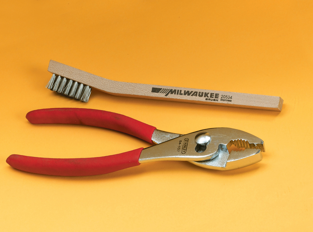
Pliers and a stainless steel wire brush are handy for gas tungsten arc welding.
Cups come in a variety of sizes denoted by 1/16" increments. A #4 nozzle is 4/16", a #8 is 8/16". Cups should ideally be 4 to 6 times the size of the electrode. A cup that is too large will not direct the gas in a proper stream, a cup that is too small may not provide adequate steady flow. A gas lens or screen in the torch balances the gas flow. Good shielding designs allow you to use a lower gas flow. Higher flow creates turbulence and jetting, which disturbs the shielding—more does not equal better when it comes to shielding gas flow. Cups also are available in different lengths. A longer nozzle increases the electrode extension from the collet, which may increase the electrode temperature. Use either lower amperage or larger diameter electrodes if you are using a longer nozzle. Shorter nozzles may be necessary for tight working conditions. Nozzles are also available in clear (fused quartz) types, which are more expensive but give greater visibility, especially in cramped quarters.
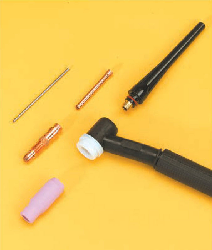
A gas tungsten arc welding torch includes the electrode, collet body, collet, cup, backcap, and torch body with heat shield.
Shielding Gases. Two inert shielding gases are used for gas tungsten arc welding: argon and helium. They may be used alone or in combination with one another. Argon yields better starts and better arc maintenance. Helium gives a hotter arc and allows faster travel speeds. Helium, however, is very expensive. Argon and helium are both contained in standard cylinders, and a pressure regulator flow meter combination will need to be attached. Because of the density difference between the two, either a separate flow meter needs to be used for each, or use a flow meter that has calibrations for each type of gas. Argon flow rates for up to 1/8" steel is 8-10 cubic feet per hour (CFH), for stainless steel 11-13 CFH, and 12-20 CFH for aluminum. Drafty locations may require higher flow rates. Check the manufacturer’s recommendations.
Electrodes. The electrode for gas tungsten arc welding is always a tungsten or tungsten alloy rod with either a pointed or rounded end. The electrodes come in a variety of diameters.
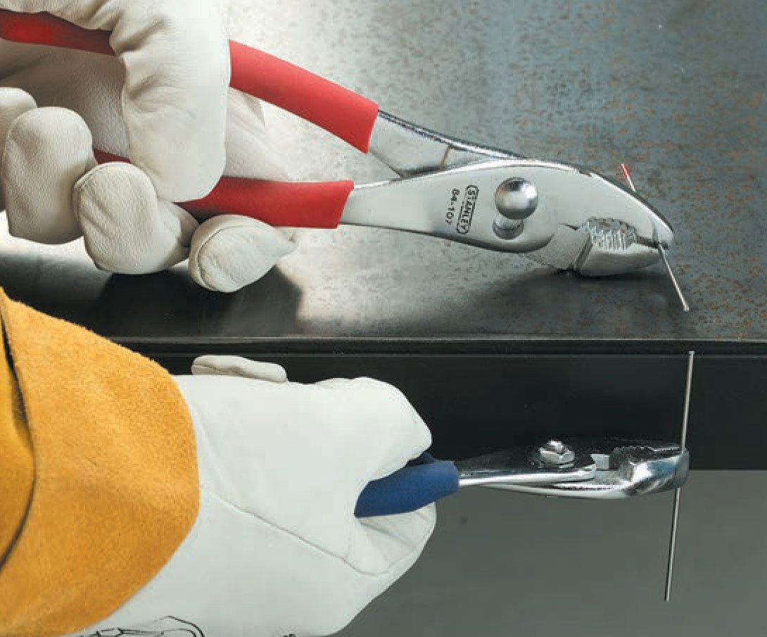
Tungsten is very brittle, so electrodes can be scored with a file, then snapped over a sharp table edge.
Preparing the Electrode. Prior to use, the cut end of the electrode must be sharpened to a point or melted to a ball. The tip may be ground to a point or chemically sharpened. The electrodes come in 7" lengths. To increase the number of points available, score the electrode with a file or cut-off wheel, and snap it in half. Tungsten is very hard but brittle, so it is easy to grasp each end of the electrode with pliers and snap it in half over a sharp table edge.
Because all tungsten electrodes look and feel the same regardless of their composition, it is important to keep them clearly separated by type. The color codes will wear off, or, if you point each end of your electrode, be ground off. It is helpful to have clearly labeled containers for each type of electrode.
Two critical factors in grinding the electrodes are the grinding wheel and the grinding direction. You must use a hard, fine grinding wheel dedicated exclusively to tungsten. Metal particles left on the wheel from grinding aluminum or steel would contaminate the tungsten, which causes erratic arc behavior and poor weld quality. An extremely hard material, tungsten will become hot as it is ground. Sharpen the electrode tip so that grinding marks run lengthwise down the tip, not in a circular or crosswise pattern. Lengthwise grinding focuses the electron flow toward the tip; circular grinding causes the arc to be unfocused and possibly jump sidewise from the electrode rather than off the tip point. Chemical means also can be used to sharpen tungsten by dipping a hot tungsten rod into a chemical agent. The length of the taper on the tungsten tip should be two to three times the diameter of the tungsten.
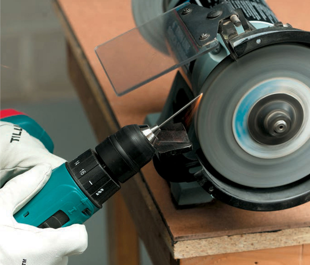
To safely hold tungstens for sharpening with a grinder, insert them into the chuck of a drill. Running the drill while sharpening the tungsten ensures a uniform point. Move the tungsten across the wheel to prevent grooves in the wheel face.
Welding with AC current requires that the tip of the electrode be balled, which is accomplished by running DC electrode positive or AC current and striking an arc on copper or brass. The ball should not extend beyond the diameter of the electrode, although many sources recommend a ball one and one half times the diameter of the tungsten.
If you touch the weld puddle or filler rod with the electrode during welding, you must change to a fresh electrode. Any time the electrode tip becomes pitted or blackened, is no longer pointed, or the ball becomes too large, you must change to a fresh electrode. This will happen often, so it is best to have a number of electrodes sharpened and ready to go. If you forget to turn on the shielding gas or the flow is interrupted, the electrode will give off a thick yellow tungsten oxide smoke. This smoke is hazardous, so resume welding only after the smoke has cleared. You will need to change electrodes if this happens.
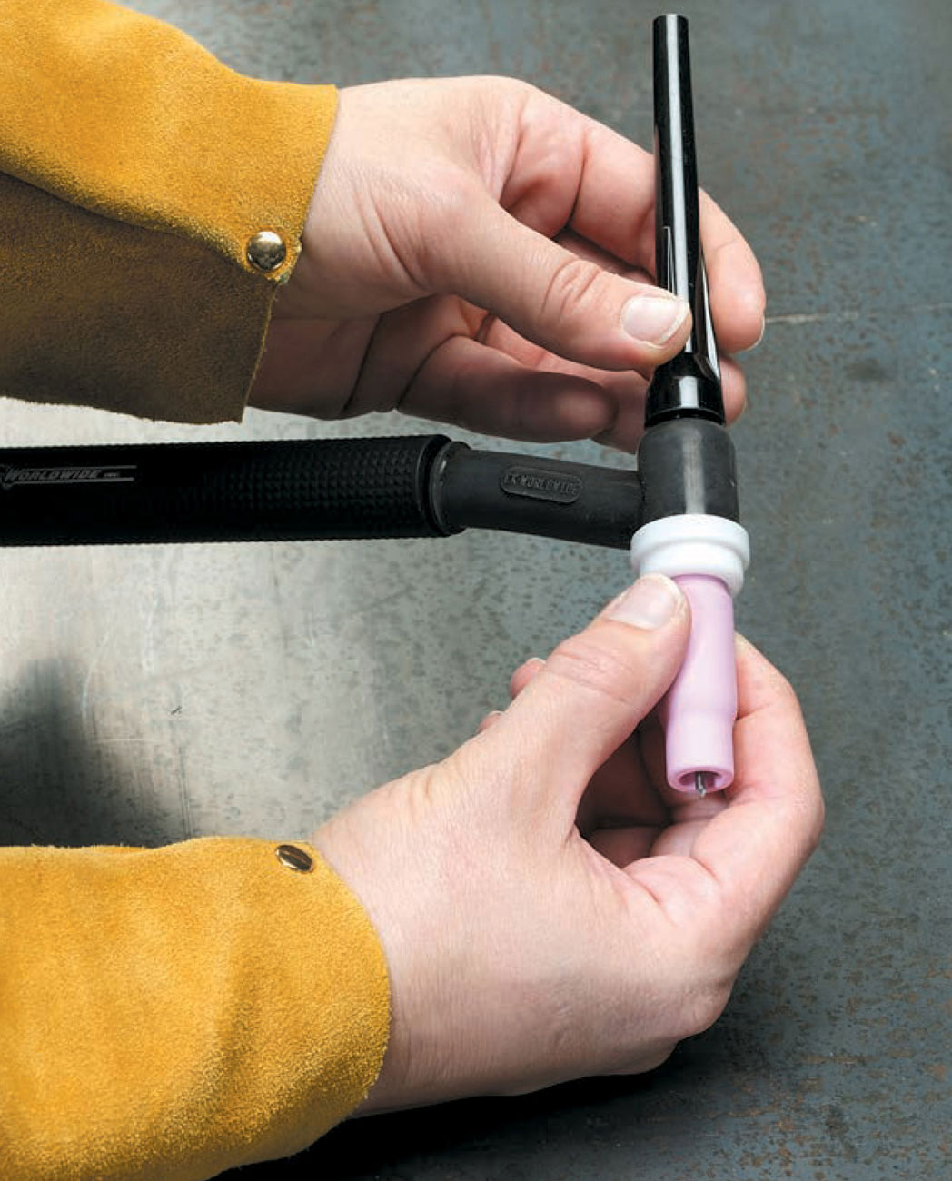
Tightening the back cap locks the tungsten electrode into place. The tip of the electrode should extend beyond the end of the cup by a distance of three times the electrode’s diameter.
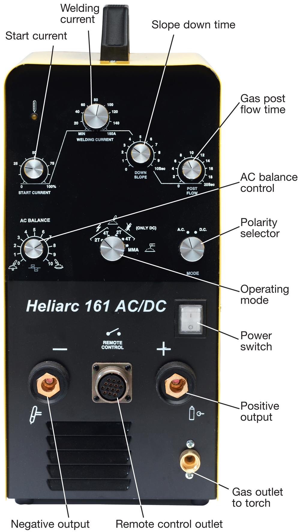
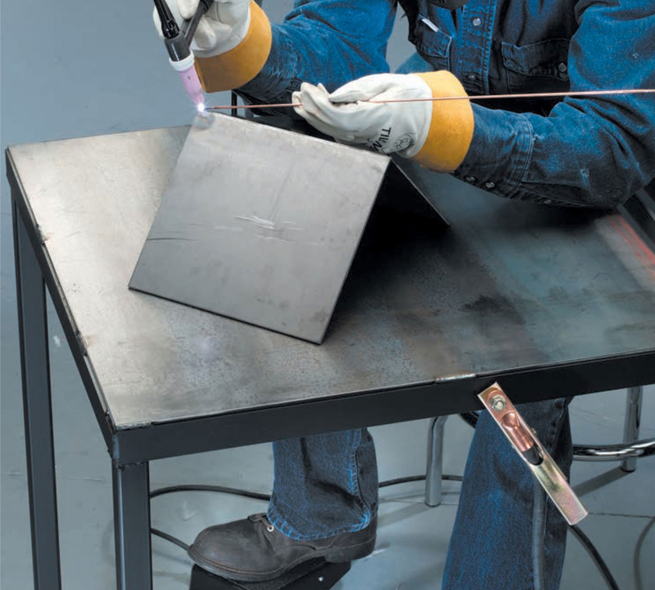
1 Set the controls based on manufacturer’s recommendations for the material to be welded. Turn on the machine, and turn on the water pump, if available. Attach the work clamp to the welding table or workpiece. Flip down your helmet, activate the foot or finger control if using one, and strike an arc by scratching the tip of the tungsten against the base metal. If your welder has a high frequency option, you do not need to scratch start the arc. Place a tack weld at each end of the joint to be welded. You may be able to tack the joint by simply fusing the two pieces with the heat of the torch, or you may have to use filler rod.
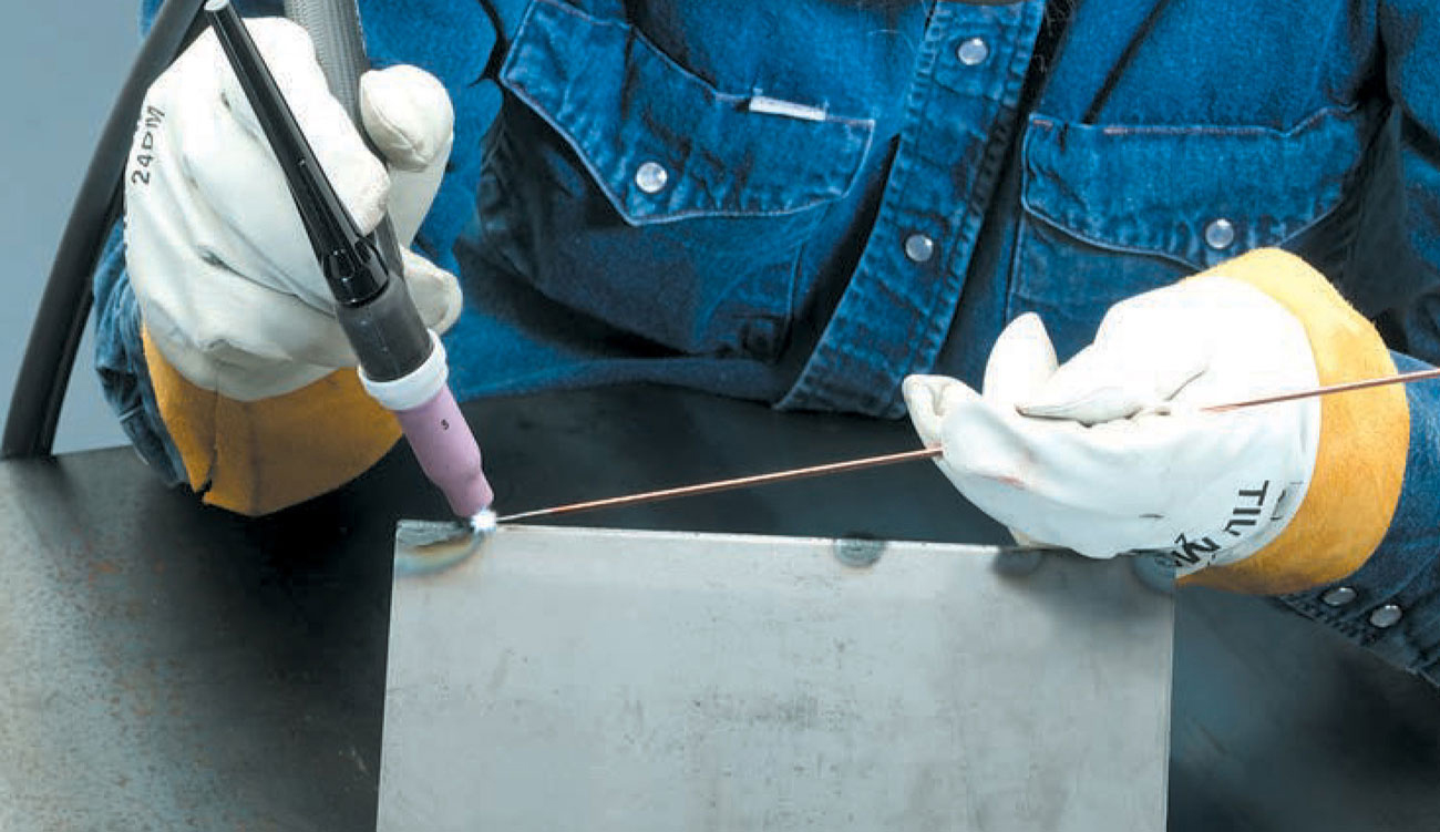
2 Position yourself to weld from right to left (if you are right handed) with the torch at a 15° angle to the right of center. Hold the filler rod in your left hand. Position yourself so you can comfortably hold the torch and filler rod for the duration of the weld.
3 When a molten puddle has formed, dip the tip of the filler rod into the middle of the molten puddle. Keep the filler rod at a low angle to prevent disturbing the shielding gas. Keep the tip of the filler rod near—but not in—the puddle. Move the electrode to the left and continue the melting and dipping process.
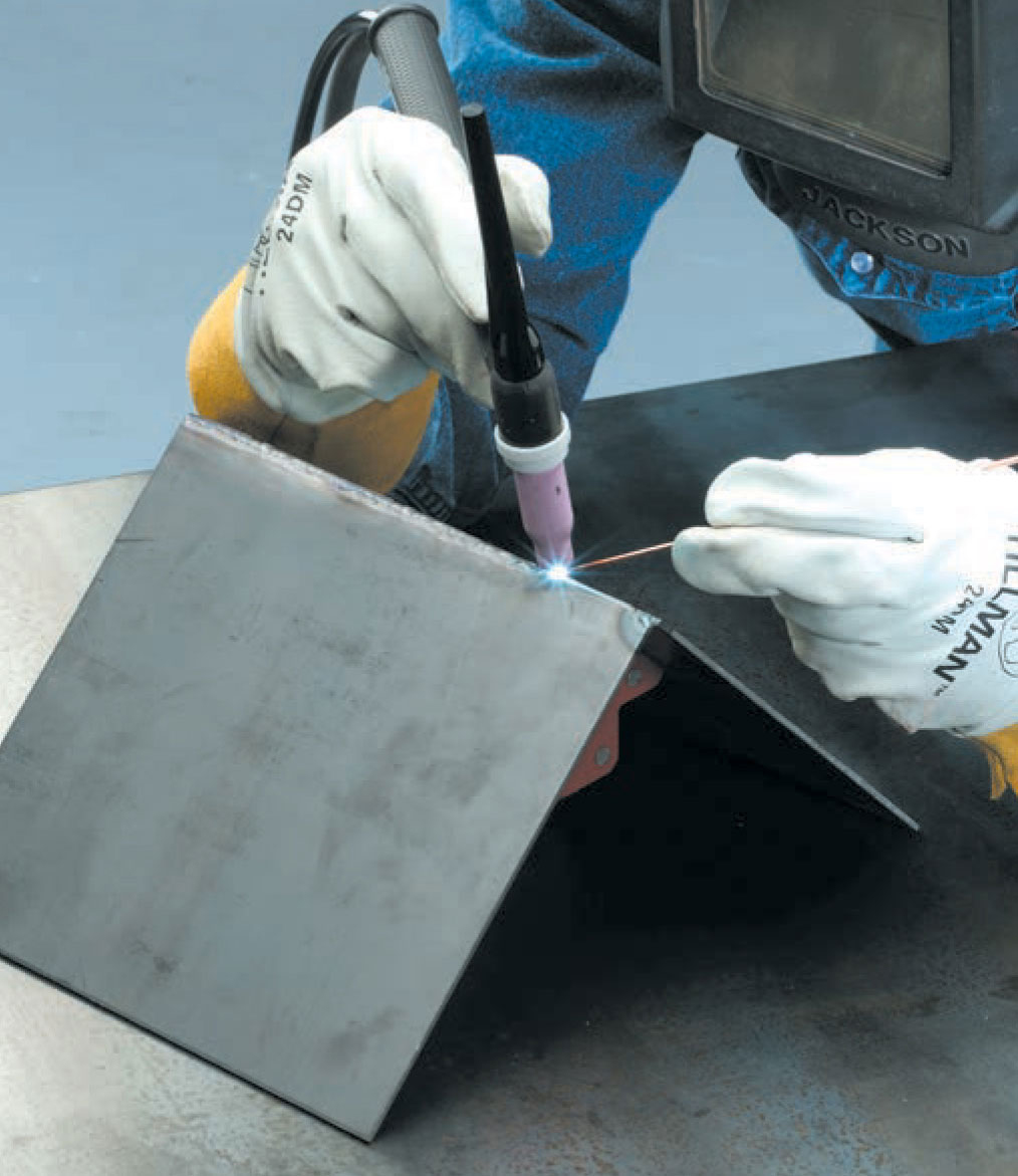
4 As you approach the end of your weld, you may need to adjust your travel speed because the buildup of heat in the material makes the molten puddle form more quickly at the end of the weld than at the beginning. You also may need to adjust the torch angle to be more shallow (not shown here) so that less heat is directed into the base metal.
Filler metal for gas tungsten arc welding comes in rod form and ranges from 1/16" to 3/16" in size. Rods are available in a variety of alloys, including aluminum, chromium and chromium nickel, copper, nickel and nickel alloys, magnesium, titanium, and zirconium. Specific alloy compositions are available for creating specific weld types on specific base metals. These filler metals are similar to those used in oxyfuel welding, with the exception of the carbon steel rods, which are not copper coated as they are for oxyfuel.
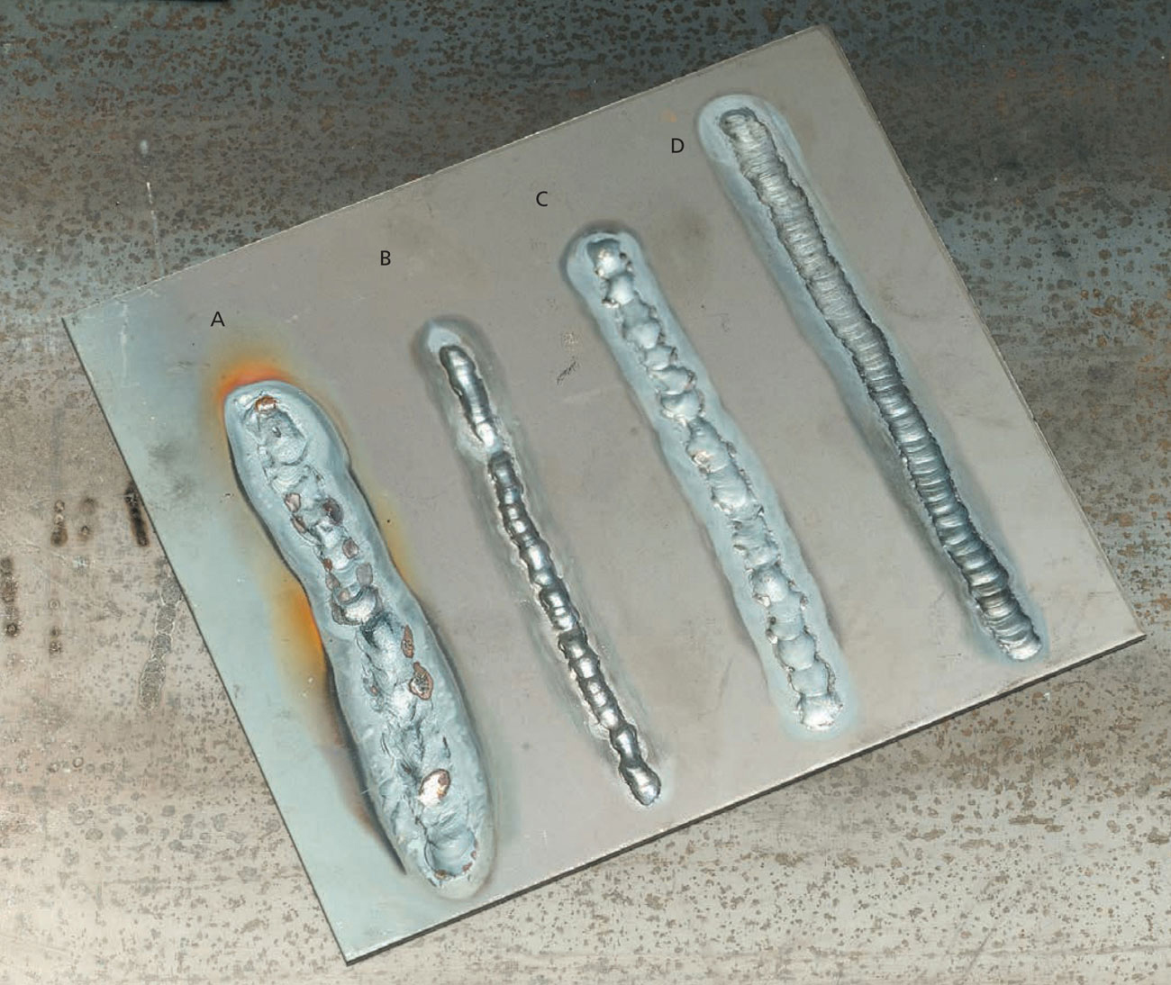
Becoming proficient in gas tungsten arc welding takes practice, and identifying problem welds is an important step. Weld A is too hot. Increase the travel speed or decrease the amperage. Weld B is too cold and is simply sitting on top of the base metal rather than penetrating it. Decrease the travel speed or increase the amperage. Weld C was done too quickly. Travel speed needs to be controlled and consistent. Weld D is a good quality weld with even ripples, good penetration, and a moderate crown.
A well-done gas tungsten arc weld on aluminum has even ripples and good penetration. This sample weld shows two passes to create a fillet weld on 1/4" stock.
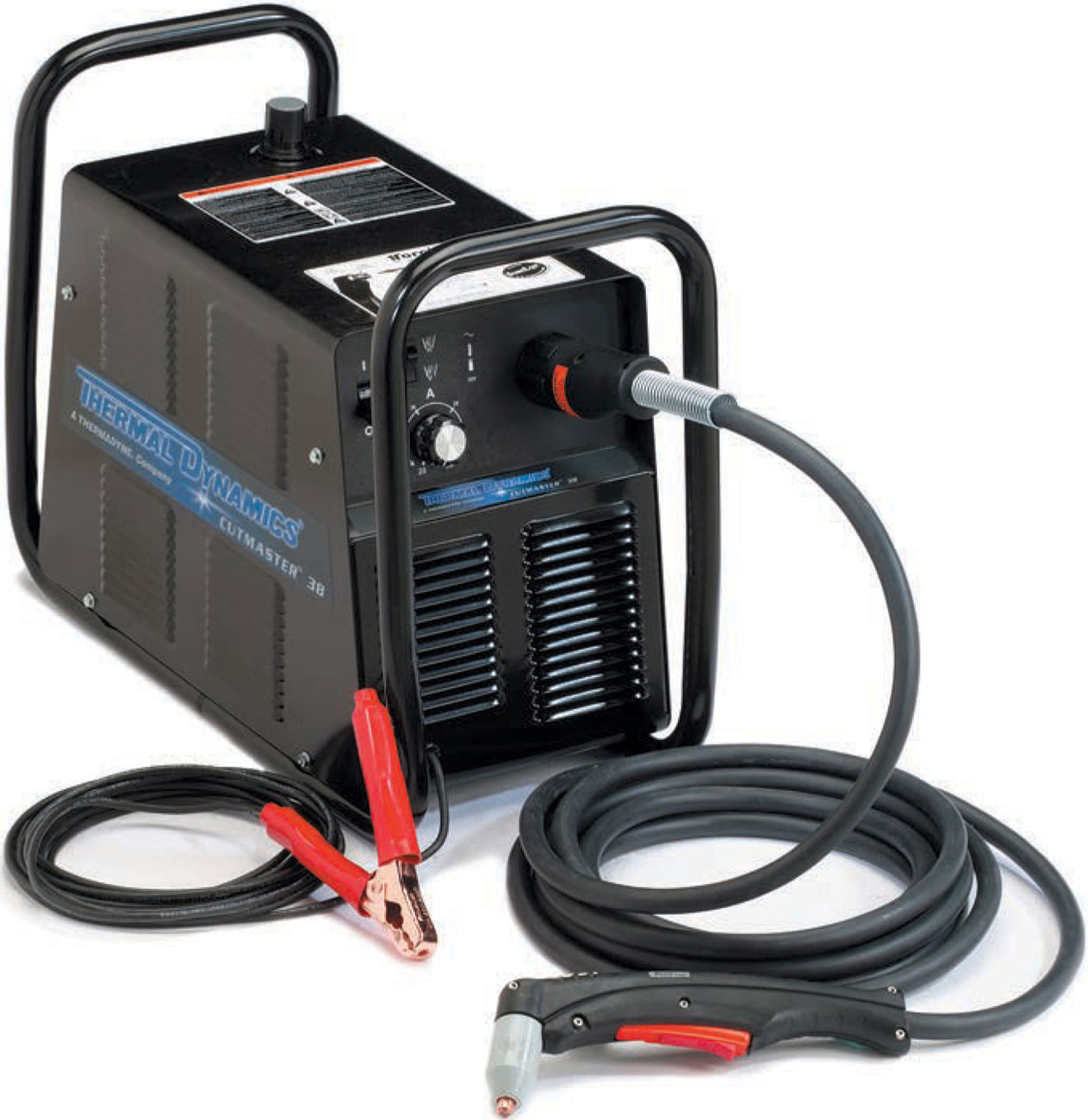
A plasma cutter consists of a power source with a compressed air or inert gas connection, work cable with clamp, supply cable, and torch.
Plasma cutting and welding are arc processes. Plasma is a gas that can conduct electricity because it is in a highly ionized form. The gas transfers the arc, but because of the constriction of the gas, the gas resistance is very high, which creates the extreme heat for plasma processes. Plasma cutting uses a very constricted arc to melt the base metal while compressed air or other gas blows the melted metal out of the kerf. This process can be used on any conductive metal—aluminum, brass, cast iron, copper, steel, stainless steel, and titanium—which sets it apart from oxy-acetylene cutting, which is only useable on oxidizable metals.
Though the plasma arc temperature is 40,000° F, it is so constricted and the cutting speed is so fast that the thermal distortion to the metal being cut is low. Plasma cuts are clean and are often weldable with no additional clean up if the base metal was initially clean. Properly done, the kerf is fairly straight sided, and no slag is present.
Safety. Plasma cutting produces sparks, smoke, and fumes. When cutting materials that contain chromium and nickel (such as stainless steel) or materials that have been galvanized or zinc coated, many toxins will be present in the fumes. When cutting through painted, bonded, or dirty metals, these surface additions often burn off, producing hazardous smoke. Plasma cutting often produces ozone and various nitrogen oxides that are colorless and can be odorless; both are hazardous. Therefore, good ventilation is important even when plasma cutting.
Plasma cutting may not seem as bright as other arc processes, but it is. It produces ultraviolet rays, so it is important to protect your skin and eyes. Because of the high level of open circuit voltage, plasma cutting has added electrical shock hazard. Make sure all surfaces around the cutting area are dry and all your clothing and gloves are dry. Turn off the power to the machine before changing any torch parts.
Never cut containers, tanks, or cylinders that may have held flammable materials. Even a small amount of flammable residue can cause an enclosed vessel to explode when cut.
Equipment. Plasma cutting machines are expensive, but as technological advances are made and demand increases, more companies are introducing smaller, less expensive home and small shop equipment. If you regularly need to cut stainless steel, aluminum, or the high strength steel now used in automobile bodies, this machine can be worth the cost. Small, 115-volt plasma cutters are available that will cut up to 3/8" material. Larger, 220-volt machines can cut thicker materials and have higher duty cycles. Aluminum and stainless steel require higher amperages, so check whether the machine easily can cut the materials with which you typically work.
Most plasma cutters require a compressed air source. Any shop air compressor that can deliver 65 psi is sufficient. It is critical that a filter be installed to keep the air dry and oil free. Follow the manufacturer’s directions for installing the filter. Some plasma cutters have an internal air compressor. These units often require more maintenance than models that utilize a separate compressor.
The plasma torch consists of a shield cup, cutting tip, starter cartridge, electrode, and torch handle. Most plasma torches have a manual switch on the torch body. The cutting tip and electrode are consumable parts. Check them frequently for wear and replace them when necessary.
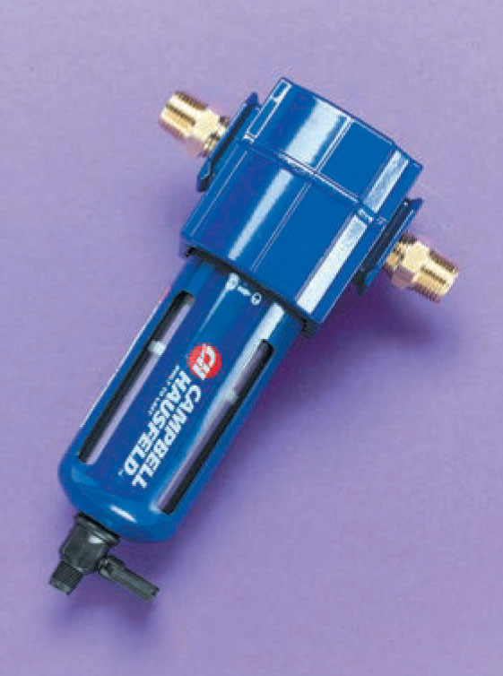
A dehumidifying filter is very important for the compressed air source for plasma cutting.
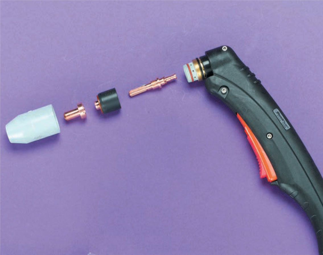
The plasma cutting torch consists of (left to right) a shield cup, cutting tip, starter cartridge, electrode, and torch handle.
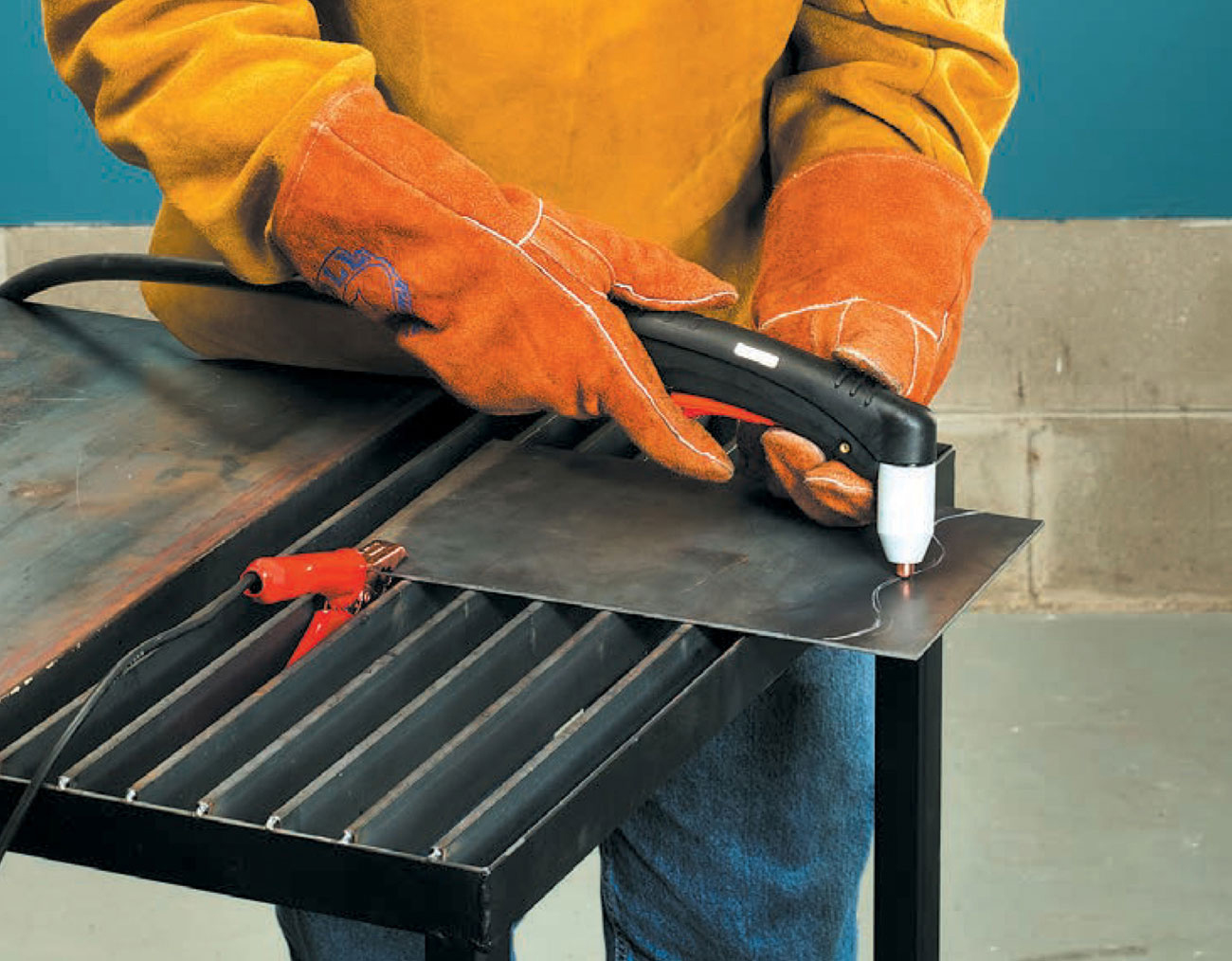
1 Check the manufacturer’s recommended settings for the material to be cut. Arrange the material on a cutting table and determine the most comfortable cutting position. Attach the work clamp to the workpiece or welding table. Dry run through the cutting motion to practice speed and cutting position.

2 Check manufacturer’s directions for arc starting procedure. Most current machines are designed to drag the nozzle directly on the material’s surface. Activate the arc and hold the torch perpendicular to the surface of the material. Move steadily and smoothly along the entire length of the cut. Do not stop the arc until you have passed through the end of the cut.
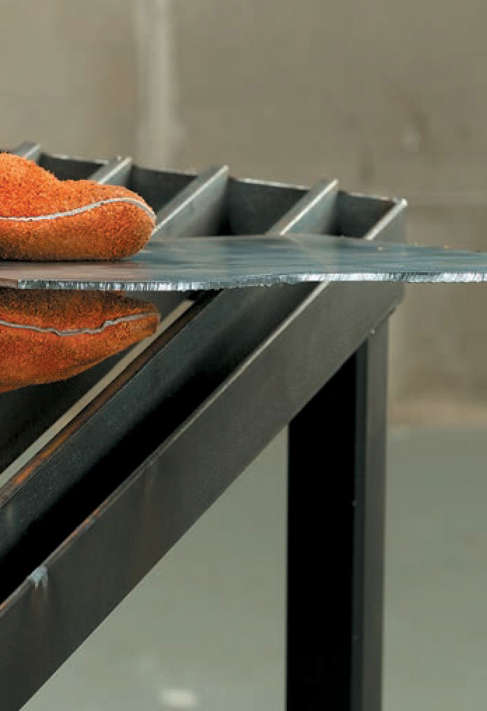
3 A good plasma cut has squared edges, small vertical ripples, and little or no slag.
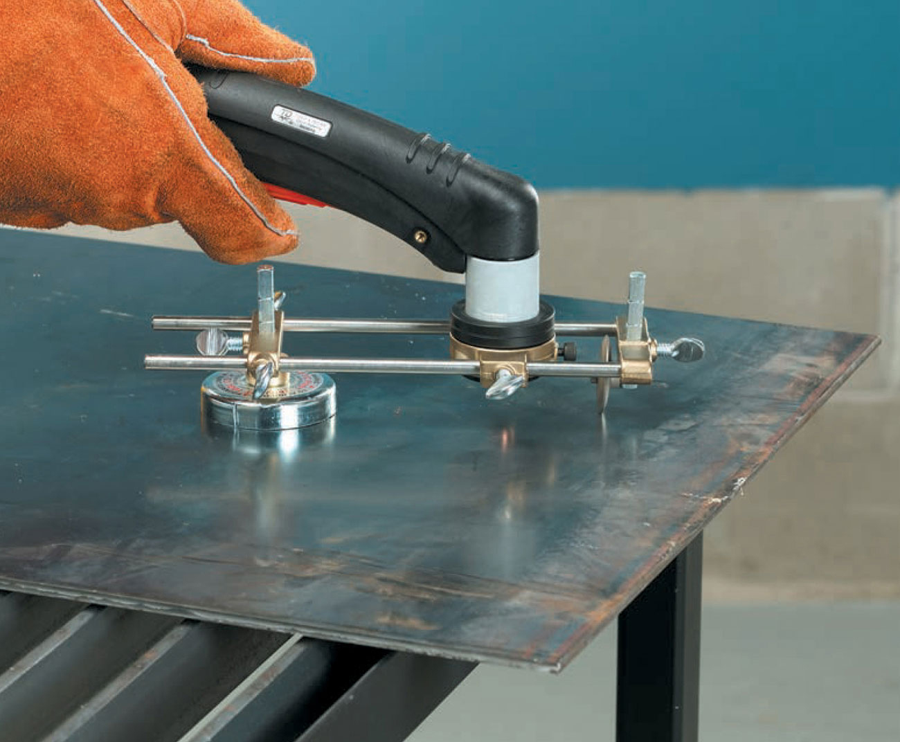
A high-quality circle cutting attachment for a plasma cutter is expensive, but worth the investment if you will be making repeated circle cuts. This unit comes with a magnetic pivot holder for steel and a suction cup pivot holder for all other metals.
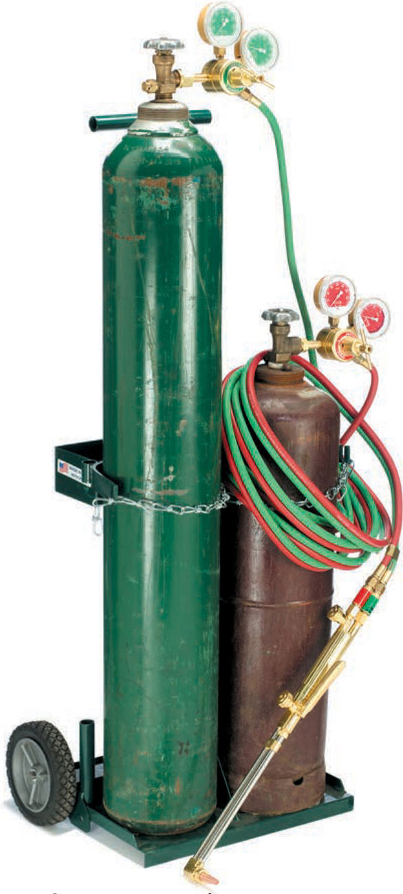
Oxyacetylene cutting equipment consists of two cylinders—oxygen and acetylene—regulators, hoses, and a cutting torch with tip.
Oxyacetylene cutting uses acetylene and oxygen to preheat metal to a temperature of 1600° F, then uses pure oxygen to burn away the heated metal. Because the cutting is achieved by oxidation of the metal, oxyacetylene cutting only works on metals that are readily oxidized at this temperature. Metals that can be cut with the oxyacetylene process are mild steel and low alloy steels. Oxyacetylene cutting can be used to cut thicknesses from less than 1/8" up to 12". Oxyacetylene cutting is inexpensive compared to machine cutting. It is very portable because no external power source is necessary, and it is faster than machine cutting. It is, however, limited to steel. The molten slag presents a fire and burn hazard, and the heat input to the base metal may cause distortion or changes to the properties of the steel.
Safety. The risk of starting a fire or being burned is high with oxyacetylene cutting. It is important to prevent molten slag and sparks from coming into contact with skin and flammable materials. Make sure you are wearing heavy-duty leather gloves with gauntlets, a leather jacket or leather-sleeved jacket, and leather boots. The work area should be cleared of flammable materials. If an item will be cut in place, make sure surrounding areas are protected from heat, sparks, and dropping slag. Never cut sealed tanks, cylinders, or items that have contained flammable materials. Never cut near gasoline tanks or fuel lines.
The Equipment. The basic equipment for oxyacetylene cutting is the same as for oxyacetylene gas welding, with the addition of a cutting torch or cutting attachment. An oxyacetylene cutting setup consists of an oxygen cylinder, an acetylene cylinder, regulators and hoses, and a torch with cutting attachment or a dedicated cutting torch. Cutting attachments and dedicated cutting torches have levers to activate the oxygen flow.
Cutting Torch & Tips. Most oxyacetylene welding sets come with a cutting accessory that attaches to the torch body in the same way that the welding tips do. A dedicated cutting torch is a one-piece unit that has its own mixing chamber. Its greater overall length allows for more distance between the heat zone and the operator, and it can handle higher oxygen flow rates. A dedicated cutting torch is usually fairly expensive and not necessary unless very thick metals will be cut, which requires greater oxygen flow.
Both the cutting torch and the cutting attachment take a variety of cutting tip sizes. The cutting tip has a number of preheat holes surrounding the pure oxygen orifice. It is important to match the cutting tip to the thickness of the metal being cut. A welder often takes a one-size-fits-all approach to cutting tips, which always results in poor-quality cuts. Thinner metals require fewer preheat holes and a smaller oxygen orifice; thicker metals require more preheat holes and a larger oxygen orifice. Cutting tips are made of copper and can be damaged easily. They need to be cleaned regularly with an appropriately sized tip cleaner.
Fuel Gas Options. Because the metal being cut does not need to be brought to the melting point, various gases other than acetylene can be used. Propane, natural gas, propylene, and methylacety-lene-propadiene can be used as the preheating fuel source. Each of these gases requires specific regulators and may require different torches and torch tips. Check manufacturer’s recommended usage before substituting an alternate fuel gas.
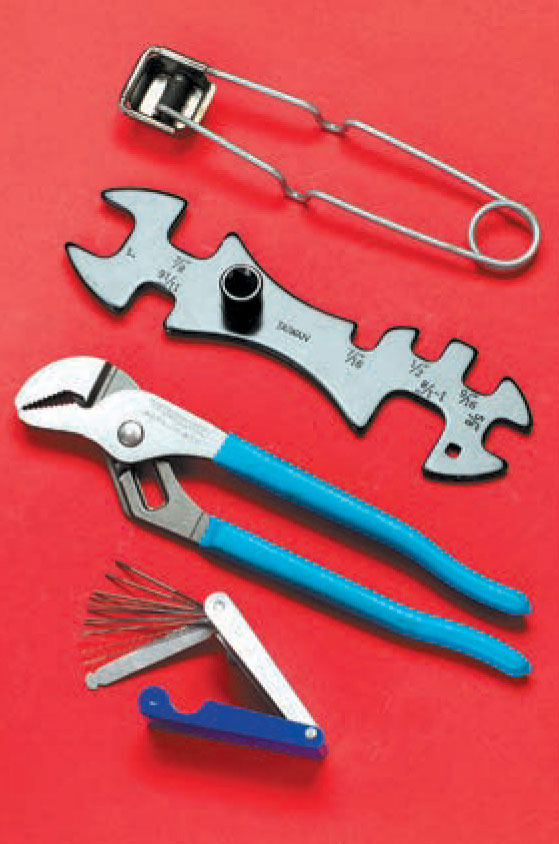
A striker, tank wrench, pliers, and tip cleaner are needed for oxyacetylene cutting.
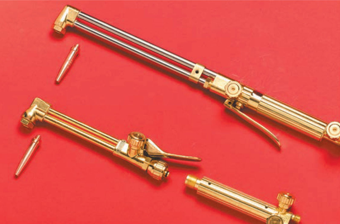
A dedicated cutting torch (top) is a one-piece unit with one oxygen and one fuel-gas valve. A cutting tip is attached to a standard torch body (bottom) and includes an additional oxygen valve. A range of tip sizes is available for both torch styles.
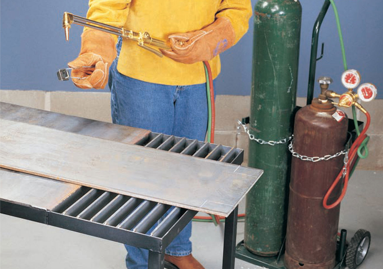
1 See pages 30 to 32 to learn how to set up, pressurize, and light an oxy-acetylene torch. Set up the material to be cut on a cutting table. Use soapstone to mark the cutting line, and practice your cutting position and bracing. Hold the torch in your left hand with your thumb and forefinger on the acetylene valve. Hold the striker in your right hand, 3" to 6" from the torch tip. Turn the acetylene valve 1/4 to 1/2 turn and strike sparks.
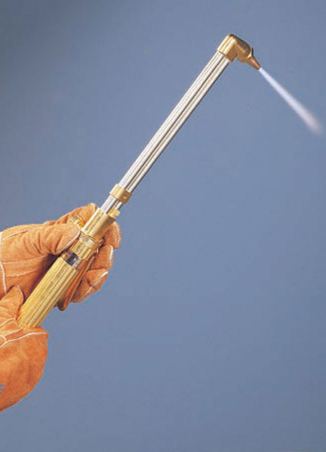
2 Adjust the acetylene so the flame is not smoking and is not separated from the tip (see page 32). Add oxygen to create a neutral flame. With a dedicated cutting torch, depress the oxygen lever to make sure neutral flame is maintained; if necessary, adjust with the oxygen lever depressed. With a cutting tip on a torch base, depress the oxygen lever and use the cutting tip adjustment valve to adjust the oxygen.
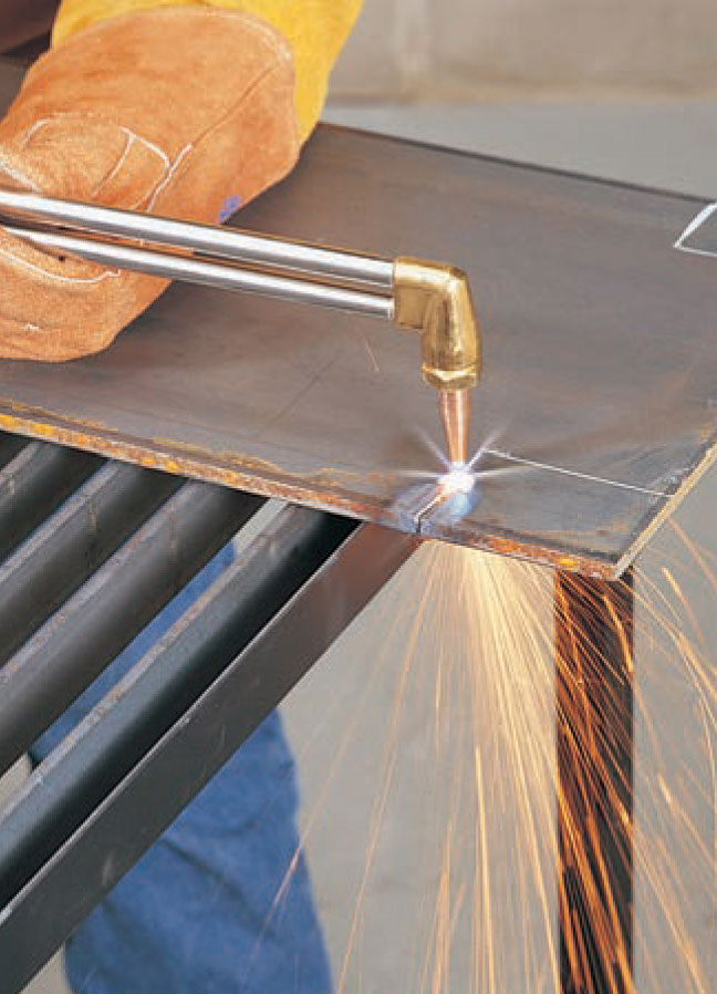
3 Release the oxygen lever, flip down your face shield, and direct the flames at the edge of the cut. Once the metal begins to glow red and appears shiny but not yet molten, depress the oxygen lever. If it fails to pierce a hole immediately, release and continue to heat until depressing the lever pierces a hole. Move slowly and steadily along the cutting line, holding the torch at a 90° angle.
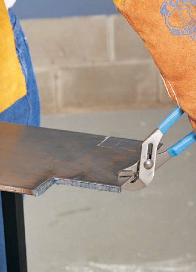
4 The finished cut should have very small vertical ridges (drag-lines), very little slag on the bottom, and the top edges should not be rounded over.
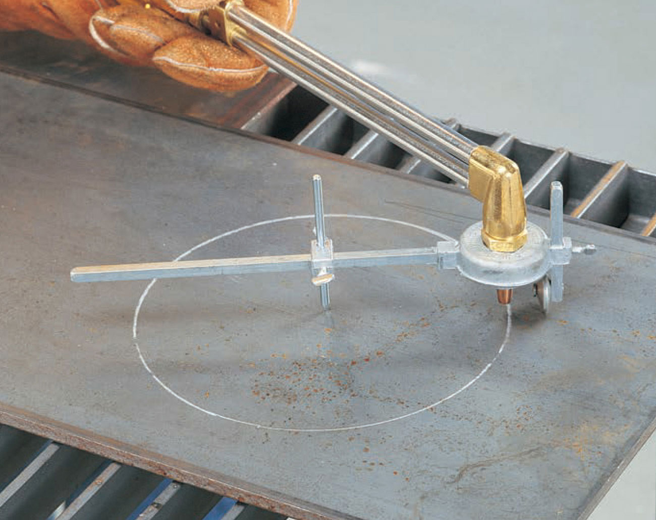
Circle cutting guides are available for making accurate circle cuts. If you need to make several circle cutouts, this can be a handy tool.
Oxyacetylene cutting produces molten slag, sparks, and hot metal scraps. Move items that are to be cut away from burnable material. If the item cannot be moved, protect surrounding areas with sheet metal and fire retardant welding blankets (not tarps). Make sure sparks and slag will not fall into cracks, holes, or ventilation grates in the floor. Wet down any wooden material around the cutting area. Have water, sand, or a fire extinguisher on hand, and monitor the area for one half hour after cutting is completed. Plan where cut metal will fall so it does not hit your arms, legs, gas hoses, or cylinders.
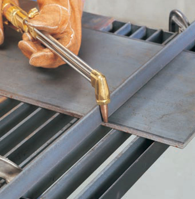
Use a piece of angle iron as a brace to support the torch or to hold pipe in place for cutting.