11-1 The Basics of Voice over IP
11-4 Analyzing VoIP Data Packets
• Examine the technologies used in the generation, management, and transport of Voice over IP calls
• Investigate the ways Voice over IP telephony can be incorporated into a network
• Develop an understanding of the key quality of service issues associated with Voice over IP telephony
• Examine the data packets generated in a Voice over IP call
weighted random early discard (WRED)
DSCP (Differentiated Services Code Point)
Secure Real Time Protocol (SRTP)
This section presents an overview of the technologies used in the generation, management, and transport of Voice over IP (VoIP) calls. The basic VoIP system begins with a telephone. IP telephones are available as standalone units or as software running on a PC. The PC requires a microphone and a speaker to support the telephone call.
Standard telephones can also be used in IP telephony if the telephones connect to a private branch exchange (PBX) that supports IP telephony. The PBX is a user’s own telephone system. It manages the internal switching of telephone calls and also interfaces the user’s phone to the PSTN (public switched telephone network—the telephone company [telco]). The interface of the IP telephone system to the PSTN is called a gateway.
PBX
Private branch exchange. The user’s own telephone system.
PSTN
Public switched telephone network—the telephone company.
Signaling
Used to establish and terminate telephone calls.
The gateway’s function is to provide an interface for IP telephony calls to the PSTN or to interface one IP telephone system with another. This requires that the voice data be packaged for transport over the IP network or the PSTN. The gateway also makes sure that the proper signaling is included for the voice data packet transport. Signaling is used to establish and terminate telephone calls and to manage many of the advanced features available with telephones.
The PSTN uses a signaling technique called SS7 that provides enhanced features:
• Toll-free services
• Worldwide telecommunications
• Enhanced call features (for example, call forwarding and three-way calling)
• Local number portability
SS7
Signaling technique used by the PSTN.
IP telephony uses different signaling techniques. The most common of these are H.323 and SIP. H.323 is a suite of protocols that define how voice and video are transported over IP networks. H.323 works with delay-sensitive traffic (for example, voice and video) to help establish a priority for timely packet delivery, critical for real-time applications. The bottom line is that the packets must arrive in a timely manner to ensure quality reproduction of the voice or video.
The Session Initiation Protocol (SIP) was developed by the Internet Engineering Task Force (IETF) to manage multimedia packet transfers over IP networks. SIP runs in the application layer of the OSI model and uses the connectionless protocol UDP for packet transport. SIP is responsible for establishing and terminating IP telephony calls and is responsible for transferring the call. A secure version of SIP has been developed called Secure Session Initiation Protocol (SSIP). SSIP provides for end-to-end secure communications by requiring user authentication.
H.323
Suite of protocols that defines how voice and video are transported over IP networks.
SIP
Session Initiation Protocol. Used to manage multimedia packet transfers over IP networks.
SSIP
Secure Session Initiation Protocol. Provides for end-to-end secure communications by requiring user authentication.
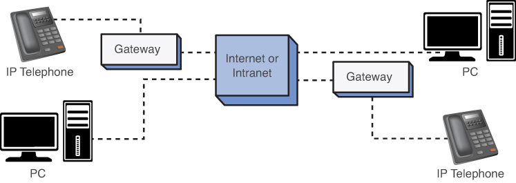
The next part of this section addresses the issues of transporting voice (telephone call) over an IP network. It was previously mentioned that VoIP telephone calls can be made from phone to phone, PC to phone, and PC to PC, as shown in Figure 11-1. The telephones connect to the VoIP gateway, and the computers connect directly to the IP network (intranet or Internet). A popular choice for Internet telephony is Skype. This service offers free global telephony service via the Internet to another Skype user.
Figure 11-1. The various ways of placing VoIP telephone calls
The first step for preparing the VoIP signal for transport is to digitize the analog voice to a PCM (pulse code modulation) digital signal (the PCM data stream). This conversion is taken care of inside the digital telephone, computer, or PBX. Processors are used to examine the PCM data stream to remove any silent spaces. Transporting data packets that contain no information (that is, silence) is a waste of bandwidth; therefore, any digitized silence is removed. The remaining PCM data is then sent to a CODEC.
The purpose of the coder/decoder (CODEC) is to structure the PCM data for inputting into frames. This involves encoding, compressing, and decoding the data.
The frames are then placed into one packet. A Real Time Protocol (RTP) header is added to each frame. The RTP header provides the following:
• Packet sequence number
• Timestamp
A companion protocol to RTP is the Real Time Control Protocol (RTCP). The purpose of RTCP is to manage packet synchronization and identification and the transport of the data.
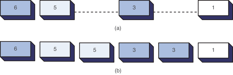
The packet sequence number is used to keep track of the order of the data packets and to detect any lost packets. RTP uses UDP for transporting the data. There is always a chance that packets could be lost in a congested network or the packets could arrive out of order. The RTP packet sequence number enables a processor to reassemble the data packets. Lost digital voice data packets will cause annoying pops and clicks when converted back to analog at the receiver. One technique is to fill in the blanks with a previously received data packet, as demonstrated in Figure 11-2. This technique helps minimize annoying pops and clicks. The substituted data packets are sometimes played back at a reduced volume to help smooth the transition.
Figure 11-2. Reconstructing the data stream at the receiver if packets are missing: (a) the received data stream with missing packets; (b) the reconstructed data stream
CODEC
Encodes, compresses, and decodes the data.
RTP
Real Time Protocol.
RTCP
Real Time Control Protocol. Used to manage packet synchronization and identification and the transport of the data.
Packet Sequence Number
Used to keep track of the order of the data packets.
Timestamps are assigned to the voice packets by RTP to provide the correct time intervals for a packet. The receivers use the timestamps to reproduce the playback of the voice packets in the same time interval sequence as recorded.
Timestamp
Reproduces playback of the voice packets with the same time interval as they were recorded.
This section examined the fundamental issues of VoIP telephony, including the technologies needed for transporting voice calls. The next section examines the steps for assembling a VoIP network.
The advantages of converging voice traffic with existing data traffic are obvious. A company can have a considerable investment in routing data traffic both internally and externally to the home network. Internally, the company will have a substantial investment in installed twisted-pair cable and wall plates for computer networks. Externally, a company might have network connections to remote sites via leased communication lines. It is a reasonable next step for the company to investigate combining voice traffic with the existing data traffic for connecting to external sites; however, best practices dictate that voice and data traffic should remain separated within the LAN. This can be accomplished by establishing VLANs to support the voice traffic.
This section examines three ways a company can implement VoIP telephony into its network:
1. Replace an existing PBX voice tie line (for example, a T1 circuit) with a VoIP gateway.
2. Upgrade the company’s existing PBX to support IP telephony.
3. Switch the company over to a complete IP telephone system.
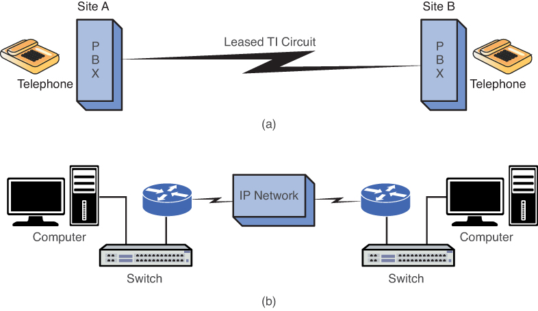
It is common practice for companies to use a PBX tie line to interconnect phone systems at different locations. The location of the PBXs could be across town from each other, or across the country or the world. The same company could also have leased data lines to interconnect the same facilities. This is shown in part a of Figure 11-3. The PBXs at each site are interconnected with a T1 tie line for the purpose of transporting telephone calls between sites. In part b of Figure 11-3, the networks are configured as a wide area data network. The company must examine the following issues:
• The company has to lease separate lines for voice (phone) and data.
• There are times when the telephone traffic is minimal and the data traffic movement could be improved if more bandwidth was occasionally available.
Figure 11-3. (a) The traditional interconnection of PBXs between sites; (b) the interconnection of data networks between sites
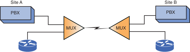
A standard solution for combining voice and data networks is to multiplex the voice and data traffic over the same tie line (for example, a T1 connection), as demonstrated in Figure 11-4. In this example, a technique called time division multiplexing (TDM) is used to divide the available bandwidth of the line interconnecting the two networks to carry both data and voice. The problem with this is the voice bandwidth is reserved for a required number of phone calls even if the calls are not being made. Combining the two networks simplifies the transport, but it doesn’t necessarily improve the overall network performance.
Figure 11-4. The use of multiplexing to combine the voice and data traffic for transport over a common T1 line
Tie Line
Line used to interconnect PBXs.
TDM
Time division multiplexing.
A VoIP solution addresses the limitations of the traditional TDM arrangement. Figure 11-5 shows the modified network. The PBXs are now connected to a VoIP gateway (also called a VoIP relay). The VoIP gateway is responsible for providing the proper signaling of the digitized voice data and encapsulating the data packets for transport over the IP network. The advantage of this arrangement is the networks can more efficiently use the available bandwidth.
Figure 11-5. The modification of the network to provide a VoIP solution
VoIP Gateway
Provides the proper signaling of digitized voice data for transport over the IP network.
VoIP Relay
Another name for a VoIP gateway.
Note that each site (see Figure 11-5) has a telephone connection to the local telephone company via the public switched telephone network (PSTN). This connection is necessary so that the phone traffic can reach users outside the network. It is also important to note that this connection serves as a backup if the Internet connection goes down.
The advantages of this arrangement are as follows:
• The voice and data traffic are combined for more efficient use of the network’s available bandwidth.
• The sites can still use the existing PBX, telephones, and connections to the local PSTN.
The potential disadvantage is that growth in data or voice bandwidth requirements can impact the telephone (voice) quality of service. Few companies will be willing to sacrifice any quality associated with telephone calls just to implement a VoIP solution. (Note: QoS issues are examined in Section 11-3.)
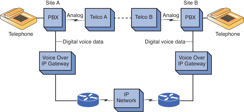
A company might decide that IP telephony should be used, but gradual steps should be taken toward IP telephony deployment. A solution would be for the company to upgrade its existing PBXs to support IP telephony. This enables the existing telephones to act like IP telephones and enable the IP telephones to place calls over the PSTN. Figure 11-6 illustrates an example of this Voice over IP solution.
Figure 11-6. An example of modifying the PBX to provide a Voice over IP solution
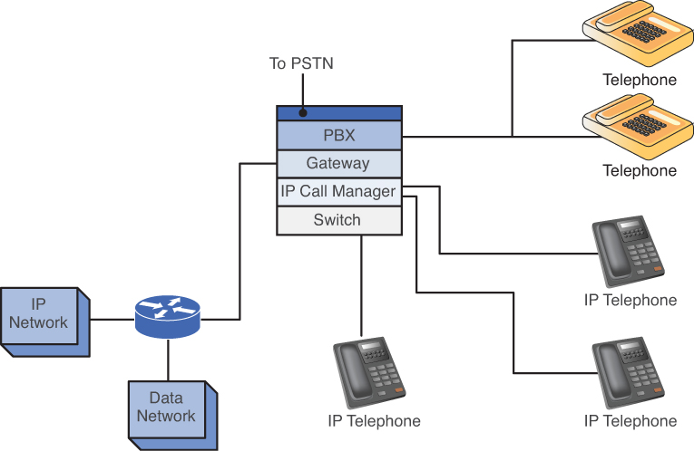
Figure 11-6 shows that the company’s PBX has been replaced or upgraded to a PBX capable of supporting IP telephony. In this example, the company is running both conventional and IP telephones. Either of these phones can place telephone calls over the IP network or via the PSTN. The conventional telephones connect to the PBX in the traditional manner. The IP telephones connect to the PBX via a network switch. The PBX will have an IP call manager for placing and receiving calls. The gateway enables both IP and conventional phone calls to exit or enter the IP network. The PBX will have a connection to the PSTN to support traditional call traffic from conventional telephones. Table 11-1 outlines the advantages and disadvantages of upgrading the PBX.
Table 11-1. Advantages and Disadvantages of Upgrading the PBX
Advantages |
Disadvantages |
Conventional telephones will now work with telephony, so existing telephone hardware doesn’t need to be replaced. |
The cost of upgrading the PBX must justify the potential benefit. |
Both PSTN and IP network voice traffic are supported. |
QoS issues still exist. |
Data traffic is easily integrated with the telephone system. |
|
The IP telephones can use existing computer network twisted-pair cable and RJ-45 wall plates to connect the new IP telephones. |
|
A company also has the option of switching completely to an IP telephone system. This requires the company to replace all its conventional telephones with IP telephones and/or PC telephones. The company’s PBX is replaced with an IP-based PBX, and a gateway is required for connecting the IP-PBX to the PSTN. Figure 11-7 shows this IP solution.
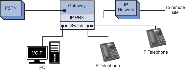
Figure 11-7. A complete IP telephony solution
Figure 11-7 shows the IP telephones connecting to the IP-PBX in much the same way computers connect to a switch in computer networking. The company’s IP-PBX connects to the remote site’s IP telephone network. The IP-PBX also contains a gateway that connects the IP-PBX to the PSTN.
The advantage of a complete IP telephony solution is that the company can use the IP network for delivery of telephone calls within the company and to any remote site connected to the Internet or that supports VoIP.
The disadvantages of a complete IP telephony solution are as follows:
• There is a startup cost of replacing old telephones with IP hardware and/or software-based telephones.
• QoS issues still exist.
• The addition of new IP phones means there are new networked devices to manage, meaning more work for the network administrator.
In today’s environment, we are seeing more and more complete IP telephony solutions. New businesses will usually start with the complete VoIP system, because it is more cost effective. In addition, one network infrastructure will be able to support both data and voice. This way there is no need to worry about a separate data infrastructure and phone infrastructure. Both networks can be run on the same copper environment (CAT5 or CAT6), on the same network switches, and on the same network router.
There have been many advancements made toward the support of IP telephony, namely with network routers. Many routers now have integrated service modules that can support Voice over IP directly. Many functions that used to require separate pieces of equipment, for example, gateways or call managers, now can be done using one router. This is a much more effective solution for small to medium sized telephony environments.
An important issue in the delivery of real-time data over a network (for example, VoIP) is quality of service (QoS). The following are QoS issues for a VoIP network:
• Jitter
• Network latency and packet loss
• Queuing
QoS
Quality of service. Refers to the guaranteed data throughput.
This section examines each of these issues and how each affects the quality of real-time voice data delivery.
Digitized voice data requires a fixed time interval between data packets for the signal to be properly converted back to an audible analog signal. However, there is a delay problem with transported voice data over a packet network. Variability in data packet arrival introduces jitter in the signal, which produces a poorly reconstructed signal at the receiver. For example, assume that a 1,000-Hz tone is sent over a VoIP network. The tone is digitized at regular time intervals, assembled into frames and packets, and sent out as an RTP packet. Random delays in the packets’ travel to the destination result in their arriving at irregular time intervals. The reproduced 1,000-Hz analog tone will contain jitter because the arrival times for each data packet will vary.
Jitter
Produces a poorly reconstructed signal at the receiver due to variability in data packet arrival.
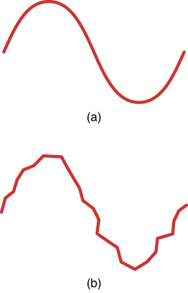
Part a of Figure 11-8 shows an accurately reconstructed sine wave, and part b of Figure 11-8 shows an unstable sine wave. This signal will contain significant distortion and may not even sound like a 1000-Hz tone at all. (Note: The bandwidth of a typical telephone call is 300–3,000 Hz. The 1,000-Hz tone was selected because it falls in the typical bandwidth for voice.)
Figure 11-8. An example of (a) an accurately reproduced sine wave and (b) a sine wave with jitter
Buffering the data packets long enough for the next data packet to arrive can minimize the effects of jitter. A buffer is temporary storage for holding data packets until it is time for them to be sent. The buffer enables the data packets to be output at regular time intervals, thereby removing most of the jitter problem. Buffering works as long as the arrival time of the next packet is not too long. If the arrival time is too late, the data packet might have to be considered “lost” because the real-time data packets can’t wait too long for the buffered packet without affecting the quality of the reconstructed signal. Another issue is that the buffering stage introduces delay, and having to wait additional time only introduces more delay.
Buffer
Temporary storage for holding data packets until it is time for them to be sent.
It takes time for a data packet to travel from the source to the destination. This is called network latency, and it becomes an important issue in VoIP data traffic. Telephones (both traditional and IP) feed a portion of the user’s voice into the earpiece. If the round-trip delay of the voice data is too lengthy (> 50 ms), the user will begin to hear an annoying echo in the earpiece.
Network Latency
The time it takes for data packets to travel from source to destination.
Delay issues can be minimized by making sure the network routers and switches are optimized for VoIP data traffic. The VoIP network can be configured so that high-priority data packets (for example, voice packets) are transported first over the IP network. Nonsensitive data packets are given a low-priority status and are transmitted only after the high-priority packets are sent.
Another source of packet delay is network congestion. This can have a negative effect on any type of data traffic but is very disruptive to VoIP telephony. The network administrator must make sure that congestion problems are avoided or at least minimized and could have the option of configuring the routers to optimize routes for IP telephony.
One technique used to minimize congestion problems is to configure the network routers and switches to intelligently discard lower-priority packets. This technique is called weighted random early discard (WRED). This is done to maintain acceptable data traffic performance of an integrated data and VoIP network. A dropped TCP/IP data packet will typically cause the TCP data packet flow to slow down. Recall from Chapter 5, “Configuring and Managing the Network Infrastructure,” that TCP issues a window size value to the number of data packets that the receiver can accept without acknowledgment. If a packet is lost, the window size decreases until an acceptable window size is obtained that doesn’t produce lost data packets. As a result, the intentionally dropped data results in a slowdown in data traffic and a less congested network.
Queuing is another technique the network administrator can use to improve the quality of service of data traffic by controlling the transfer of data packets. The administrator must identify the data traffic that must be given priority for transport. The queuing decision is made when the data packet arrives, is first queued, and placed in a buffer. There are many types of queuing arrangements, with the most basic being FIFO (first in, first out). In this case, the data packets are placed in the queue on arrival and transmitted when the channel is available.
Weighted Random Early Discard (WRED)
Network routers and switches are configured to intelligently discard lower priority packets.
Queuing
Provides control of the data packet transfer.
First Queued
Describing when the data packet arrives.
FIFO
First in, first out. The data packets are placed in the queue on arrival and transmitted when the channel is available.
A technique called weighted fair queuing (WFQ) is available on many routers and is used to determine what data traffic gets priority for transmission. This technique applies only if the buffer is full, and a decision must be made as to which data packet goes first. WFQ can be modified to provide a class-based weighted fair queuing (CBWFQ). This improvement enables the network administrator to define the amount of data traffic allocated to a class of data traffic (for example, VoIP).
Other queuing techniques are PQ and CQ. Priority queuing (PQ) is used to make sure the important data traffic gets handled first. Custom queuing (CQ) reserves a portion of the channel bandwidth for selected data traffic (for example, VoIP traffic). This is a decision made by the network administrator based on experience with the network. The problem with CQ is that it doesn’t make allowances for other traffic management when the channel is full; therefore, queuing techniques, such as WFQ or WRED, can’t be used to manage the data flow. The queuing techniques available to the network administrator are as follows:
• FIFO (first in, first out)
• WFQ (weighted fair queuing)
• CBWFW (class-based weighted fair queuing)
• PQ (priority queuing)
• CQ (custom queuing)
Weighted Fair Queuing (WFQ)
Used to determine what data traffic gets priority for transmission.
CBWFQ
Class-based weighted fair queuing. Enables the network administrator to define the amount of data traffic allocated to a class of data traffic.
PQ
Priority queuing. Used to make sure the important data traffic gets handled first.
CQ
Custom queuing. Reserves a portion of the channel bandwidth for selected data traffic.
Two additional areas for consideration in regards to QoS for VoIP are incorporating the use of VLANs within your network to separate voice and data traffic and securing your voice traffic:
• VLANs for VoIP: When deploying VoIP on LANs, it is recommended that a separate VLAN be created on your network for IP telephony. The advantage of this is the voice and data networks are kept separate. Network slowdowns or security threats to the data network will not affect the VoIP network or are at least kept to a minimum.
• Securing the VoIP network: The traditional PBX used in telephony is not typically vulnerable to the security threats that occur on data networks. However, VoIP networks are vulnerable to similar security threats. The most serious threat to VoIP traffic is denial of service (DoS) attacks. DoS attacks work by flooding the network with server requests or excessive data traffic. The result is a severe degradation in the QoS available for VoIP telephony. Another threat to the quality of service is spam over Internet telephony (spit). In this case, the VoIP network can be saturated with unsolicited bulk messages broadcast over the VoIP network.
A minimum typical QOS configuration consists of a class map, and a policy-map. A class map defines a group or a selection of IP telephony endpoints. A class map can be configured to match based on Layer 3, Layer 4, or even Layer 7 classifications. A policy map is used to specify a series of actions to be performed on each criteria match of the class map:
Spit
Spam over Internet telephony. A situation where the VoIP network can be saturated with unsolicited bulk messages broadcast over the VoIP network.
class map
Defines a group or a selection of IP telephony endpoints.
policy map
Used to specify a series of actions to be performed on each criteria match of the class map.
class-map match-any Voice
match access-group 101
match ip dscp ef
class-map match-any Signaling
match access-group 102
match ip dscp af33
!
!
policy-map WAN
class Voice
priority percent 30
class Signaling
bandwidth percent 5
class class-default
fair-queue
!
access-list 101 remark __________________________________________
access-list 101 remark ACL for QoS class-map Voice for VoIP
access-list 101 remark ------------------------------------------
access-list 101 permit udp 10.99.55.0 0.0.0.255 any range 16384 32767
access-list 102 remark ______________________________________________
access-list 102 remark ACL for QoS class-map Signaling for VoIP
access-list 102 remark ----------------------------------------------
access-list 102 permit tcp any any range 2000 2002
access-list 102 permit tcp any any range 5060 5061
The example shows two class maps: one is called Voice and another is called Signaling. The class map, Voice, is created by matching either the traffic as specified by access list 101 or the DSCP value. The access list 101 defines traffic from the network 10.99.55.0/24 to any UDP port in the range of 16,384 to 32,767. VoIP uses the UDP traffic within the range to voice packet transmission. If a match is not found, the class map will match the packet based on the DSCP value. DSCP (Differentiated Services Code Point) is the six most significant bits of the Diffserv Field in the IP header. DSCP is used to specify a QoS value of an IP endpoint. The class map specifies that the value of DSCP field in the IP header must be set to EF (Expedited Forwarding), which has a binary value of 101110. Another class map, Signaling, is created to ensure the VoIP signaling or handshake. This class map matches either the traffic specified by access list 102 or the DSCP value. The first statement in the access list 102 defines any TCP traffic to port 2000, 2001, and 2002 and the second statement defines any TCP traffic to port 5060 and 5061. Another match used by the class map is the DSCP value of AF33 (Assured Forwarding class 3), which has a binary value of 011110. Once a class map is defined, a policy map called WAN is then created to associate the class maps to the QoS actions. In this case, the class map Voice will be guaranteed 30 percent of the bandwidth of the interface to which it is applied. The class map will be guaranteed 5 percent of the bandwidth of the interface to which it is applied. The rest of the bandwidth will be given to the default class, which is the traffic that is not defined by the class maps.
DSCP (Differentiated Services Code Point)
Six most significant bits of the Diffserv Field in the IP header.
EF
A class map that specifies that the value of DSCP field in the IP header is set to Expedited Forwarding.
AF33
Assured Forwarding class 3. Created to ensure the VoIP signaling or handshake.
An important QoS and safety issue is the ability to place emergency 911 calls using your phone system. The traditional phones that connect to the PSTN can be traced to your location. However, VoIP calls are a transfer between IP addresses and, with VoIP, there currently isn’t a way to determine the physical location of the caller. However, the FCC has developed the Enhanced 911 (E911) feature to address this problem. The E911 standard requires all VoIP service providers to pass the name and the address information to the nearest Public Safety Access Point (PSAP) when 911 is dialed. It is important that you verify that your VoIP service provider supports E911.
E911
Enhanced 911. Requires all VoIP service providers to pass the name and the address information to the nearest Public Safety Access Point (PSAP) when 911 is dialed.
Another important QoS issue is the potential loss of service due to power outage. Traditional phones that are operated by the PSTN maintain operation during power outages because they operate on stand-by power. Of course, the VoIP system can be designed to operate with a battery backup system, but this can be a substantial investment. A possible solution is to keep a regular telephone as a backup, but this will add to your overall operational cost.
This section has presented the key quality of service issues in the delivery of real-time data (VoIP). The network administrator must be aware of these techniques and how each can be used to improve the VoIP QoS. The administrator must also be aware of the tradeoff that optimizing an IP network for VoIP traffic can have on the data network.
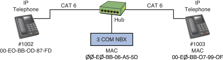
This section examines the packets exchanged during VoIP calls using both voice over Ethernet and Voice over IP. The VoIP data collected for the voice over Ethernet discussion were generated from an IP telephone network that contained two IP telephones and a call processor. Figure 11-9 shows a block diagram of the setup for the circuit. The communications used for these phones is running at Layer 2, the data link layer. The IP phones and the call processor were configured with IP addresses, but the phones are in the same LAN, and IP routing was not necessary. This setup is similar to the phone setup in an office or a small business. The MAC addresses for the networking equipment are listed in Table 11-2.
Figure 11-9. The setup used to collect the VoIP telephone call data packets
Table 11-2. MAC Addresses for Networking Equipment Used When Gathering VoIP Data Packets
Networking Device |
MAC Address |
Phone (#1002) |
00-E0-BB-0D-87-FD |
Phone (#1003) |
00-E0-BB-07-99-0F |
Call processor |
00-E0-BB-06-A5-5D |
There are some basic codes used by this particular call processor to identify the packet running over the Ethernet network. These codes identify the type of message that is being issued, such as voice data packets, request packets, and acknowledgments. These codes, listed and described in Table 11-3, will be used when analyzing the VoIP data traffic.
Table 11-3. IP Telephone Call Packet Codes for the Call Processor
Code |
Letter |
Description |
0x41 |
A |
Voice data packets |
0x48 |
H |
Acknowledgment |
0x52 |
R |
Request packet, issued when a button is pressed |
0x55 |
U |
Update |
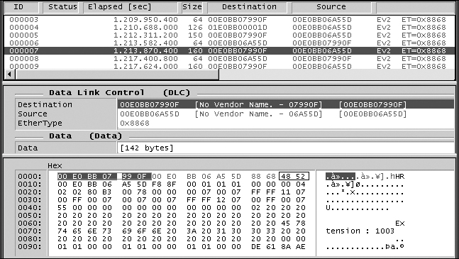
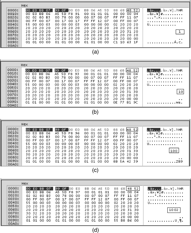
The following discussion is for a set of voice call data packets obtained using the setup shown in Figure 11-9. The first packet examined is number 7. This packet is from the call processor (MAC 00-E0-BB-06-A5-5D). It is acknowledging that the #1003 phone has been picked up. Phone #1003 has a MAC address of 00-E0-BB-07-99-0F. The data in Figure 11-10 indicates Extension:1003 has been picked up. The code for the call is the hexadecimal numbers (0x48 52). The code is shown boxed in Figure 11-10. This code indicates that the packet includes an acknowledgment (48) and a request (52). In the next data sequence, the #1003 phone begins to dial #1002. The following data packets show the call processor’s acknowledgment (code 48) of the buttons as they are pushed. Only the contents of the data packet will be displayed. The sequence is provided in Figure 11-11 (a–d).
Figure 11-10. The acknowledgment that phone #1003 has been picked up
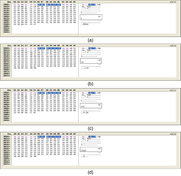
Figure 11-11. (a) The acknowledgment that phone #1003 has pressed number “1”; (b) the acknowledgment that phone #1003 has pressed number “1 0”; (c) the acknowledgment that phone #1003 has pressed number “1 0 0”; (d) the acknowledgment that phone #1003 has pressed number “1 0 0 2”
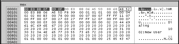
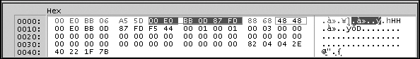
The next sequence first shows the call processor notifying phone #1003 that it is dialing #1002 in Figure 11-12. Figure 11-13 shows phone #1002 acknowledging the call from the call processor, basically coming online. The codes (48 48) are acknowledgments that the request was received.
Figure 11-12. The message from the call processor that it is dialing #1002
Figure 11-13. The acknowledgment of the call from phone #1002 back to the call processor
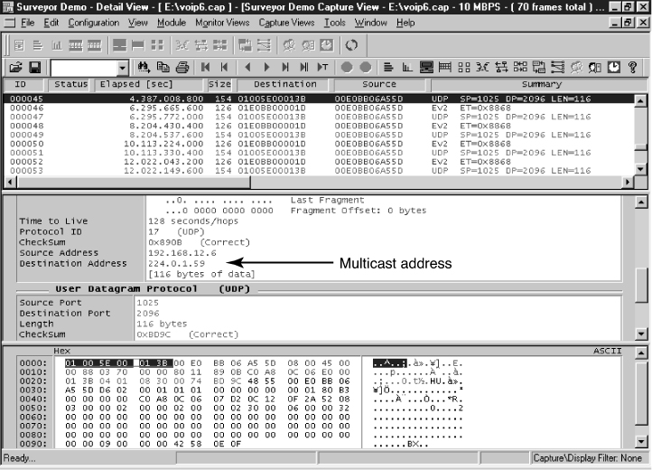
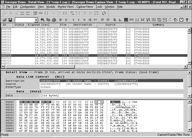
Phone #1002 has acknowledged the call, and now the call processor will go through multiple management steps to complete the call. This is shown in Figure 11-14. Notice in Figure 11-14 that the UDP data packets are being used with a source IP address of 192.168.12.6. This is the IP address of the call processor. The destination IP address for the highlighted data packet is 224.0.1.59. This is a multicast address used by the call processor to manage the call setup and functions. This is used only for call setup. Once the call is set up, the IP phones will begin transferring the voice data. This is shown in Figure 11-15. The code for the data packets has changed to (41), which is for “voice” data packets. Notice that the source and destination MAC addresses are alternating during the conversation. The IP phones are communicating directly without further need of the call processor. The data shown at the bottom of Figure 11-15 is the PCM voice data.
Figure 11-14. The call processor’s management steps to set up the phones so that voice data transfer can begin
Figure 11-15. The exchange of voice packets (code 41) between the two IP phones
This section has demonstrated the call setup and signaling for establishing an IP telephone call within a local area network. The transfer of the voice data packets between IP phones has also been shown. The reader should understand how the basic call was established and how to identify the type of message using the call codes (see Table 11-3). The reader should also understand that the call processor uses multicast addresses to set up the call before handing it over to the IP phones.
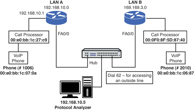
This section examines the data packets that are being exchanged in a VoIP telephone call. The test setup for the VoIP telephone call is shown in Figure 11-16. This picture shows that the network consists of two VoIP telephones, two call processors, and two routers. The data packets were captured using a network protocol analyzer. The computer running the protocol analyzer and the two call processors were connected to a networking hub so that each share the Ethernet data link. This was done so that all the VoIP data packets being exchanged between the telephones, the call processors, and the routers could be captured at the same time with one protocol analyzer.
Figure 11-16. The test setup for the VoIP telephone call
In the following example, a telephone call is being placed from extension 1006 to the 62-2010 extension. The first packet examined is number 5, shown in Figure 11-17. This packet source is from the LANA call processor with the MAC address of 00:E0:BB:1C:27:C9. The HR text (indicated by the arrow) is an acknowledgment that extension 1006 (00:e0:bb:1c:07:0a) was picked up to dial the call. The call packet codes for the call processor are listed in Table 11-3. H (0x48) is an acknowledgment, and R (0x52) is a request packet that is issued when a button is pushed.
Figure 11-17. The acknowledgment that extension 1006 was picked up
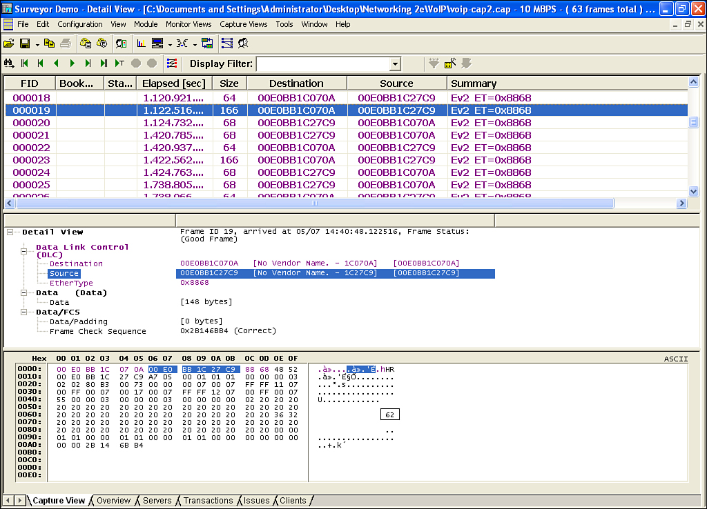
Packet number 19 (see Figure 11-18) shows the call processor (00:E0:BB:1C:27:C9) acknowledging back to extension 1006 (00:e0:bb:1c:07:0a) dialing the number 62 to go outside the network (LAN A) to talk to the destination phone in LANB. The 62 is the number used by the call processor to get an outside telephone line. This is defined in the call processors call plan. Once again, the HR code is listed at the beginning of the data packet. The HR codes will repeat throughout the call setup, Figure 11-19 (a–d).
• Packet number 23 (see Figure 11-19 [a]) is showing ext. 1006 dialing the first number “2” in the corresponding phone number on LAN B.
• Packet number 27 (see Figure 11-19 [b]) is showing ext. 1006 dialing the second number in the corresponding phone number on LAN B.
• Packet number 33 (see Figure 11-19 [c]) is showing ext. 1006 dialing the third number in the corresponding phone number on LAN B.
• Packet number 39 (see Figure 11-19 [d]) is showing ext. 1006 dialing the forth number in the corresponding phone number on LAN B.
• Packets 41–52 (see Figure 11-19) are showing the handshaking between the two networks. Notice that the source and destination have changed to the IP addresses for the VoIP telephone call.
Figure 11-18. Dialing “62” for an outside line
Figure 11-19. Dialing the outside line at 62–2010
Finally, Figure 11-20 shows the packets exchanged between the two IP phones.
Figure 11-20. The handshaking between the two IP networks and the start of the VoIP telephone call
This section demonstrated the call setup and signaling for establishing a VoIP telephone call within two networks. The student should understand how the basic call was established (same as voice over Ethernet) and that dialing “62” was required to get an access line.
A question you might ask is if there are security issues with VoIP data traffic? It was shown in this chapter that the network set up and data traffic for VoIP are similar to the expected data traffic in any network. Therefore, similar security concerns exist. For example, the VoIP network can be attacked, so there is a potential for packet sniffing, eavesdropping, and denial of service (DoS). The threat of eavesdropping presents the potential problem that the VoIP data packets can be intercepted. If the packets are intercepted, then it is possible that the audio portion of a phone conversation can be replayed using free software that converts the VoIP data packets to .wav or .au files.
What steps does the network administrator need to take to protect and secure a VoIP network? Possible security steps include the following:
• Encrypting the VoIP data traffic
• Using firewalls to prevent attacks
• Route VoIP data traffic on separate LANs than normal data traffic
Techniques for encrypting VoIP data traffic include IPsec and the Transport Layer Security (TLS). IPsec is a suite of protocols used for securing network connections. This is applied to the call set up and the conversation data packets. The TLS protocol enables network devices (including VoIP devices) to securely communicate across a network. Once a connection is established, both members of the network negotiate a stateful connection. This is important because this will enable VoIP data traffic to pass through a stateful firewall.
Many VoIP systems use RTP (Real Time Transport Protocol [refer to Section 11-1]) for the transmission of real-time Internet telephony. The problem is RTP is considered to be insecure and the possibility exists of someone eavesdropping on conversations. A solution to this problem is the use of the Secure Real Time Protocol (SRTP). This protocol provides confidentiality, message authentication, and replay protection of VoIP data.
Secure Real Time Protocol (SRTP)
This protocol provides confidentiality, message authentication, and replay protection of VoIP data.
There are many possible threats to VoIP networks. The most common categories of threats include the following:
• Availability: Phone systems are intended to be operation 24x7. This means that any threat to availability is a concern. Threats of this type can include interruption of service, call flooding, and call hijacking.
• Confidentiality: Ensures that information is not accessed by unauthorized persons.
• Integrity: A concern is the verification that the message has not been intercepted and altered. The attacker can potentially alter the message.
• Social Context: This concern addresses the issue where an attacker misrepresents himself to the victim thereby creating trust that enables the attacker to be a trusted member of the network.
Firewalls allow traffic from inside the network to exit but don’t allow general traffic from the outside to enter the network. The firewall monitors the data traffic and recognizes where packets are coming from. The firewall will allow packets from the outside to enter the network if they match a request from within the network.
In a stateful firewall, the inbound and outbound data packets are compared to determine if a connection should be allowed. This includes tracking the source and destination port numbers and sequence numbers as well as the source and destination IP addresses. This technique is used to protect the inside of the network from the outside world but still allow traffic to go from the inside to the outside and back. The firewall needs to be stateful to accomplish this.
As stated in Section 11-3, a good rule is to route VoIP data traffic on separate LANs from traditional data traffic. This will help protect both networks from possible intrusions and viruses. At least if one network is compromised then the other network will remain unaffected.
Another issue to be aware of is that adding security to a VoIP network has the potential of affecting quality of service issues (refer to Section 11-3). The three potential issues that can be affected include
• Latency
• Jitter
• Packet loss
Latency is the time for a data packet to travel from the source to the destination. This is called network latency, and it becomes an important issue in VoIP data traffic. Telephones (both traditional and IP) feed a portion of the user’s voice into the earpiece. If the round-trip delay of the voice data is too lengthy (> 50 ms), then the user will begin to hear an annoying echo in the earpiece. Variability in data packet arrival introduces jitter in the signal, which produces a poorly reconstructed signal at the receiver. The same is also true for packet loss which results in a poorly reconstructed signal.
Is it easy for the attacker to intercept VoIP calls? It actually takes someone who is technically sophisticated to intercept VoIP telephone calls. VoIP systems have two possible types of vulnerabilities. The first is the level of network security that is running the VoIP data traffic. Threats of intrusion and denial of service for VoIP networks are the same that exist in a traditional data network. A well-protected infrastructure will help to better secure the network.
The second issue consists of the security issues associated with the VoIP protocols and the many pieces of VoIP hardware required to setup the network. There are many pieces required to put together a VoIP network and with it are the introduction of many security threats. The VoIP network will never be 100 percent secure, but adding a suite of security tools, including hardware and software, will make the network fairly secure.
This chapter presented an introduction to Voice over IP telephony. The network administrator must be aware of the impact of integrating VoIP into the network. Advancements in technology are making the integration of voice and data easier, but along with the simplification comes the requirement that the network administrator fully comprehend the capabilities and limitations of the technologies. The student should understand the following concepts:
• How IP telephony interfaces with the PSTN
• The signaling techniques used by IP telephony
• The steps for preparing the VoIP signal for transport
• How VoIP can be integrated into a company’s network
• The quality of service (QoS) issues for VoIP
• The importance of using VLANs for VoIP traffic within the LAN
• The potential security threats for VoIP
• The types of data packets issued when setting up a VoIP call
1. Define PBX.
2. Define PSTN.
3. What is the purpose of a gateway?
4. List four enhanced features of SS7.
5. What are the signaling techniques used in IP telephony?
6. What are RTP and RTCP used for in VoIP?
7. What does a processor in a VoIP receiver do if a voice data packet is lost?
8. How is the timestamp on VoIP data packets used?
9. What are three ways a company can implement VoIP into their network?
10. What is a standard solution for combining voice and data traffic?
11. What is the purpose of a VoIP gateway?
12. What is another term for a VoIP gateway?
13. What are two advantages of replacing an existing PBX tie line with a VoIP/data network?
14. What is the disadvantage of replacing an existing PBX tie line with a VoIP network?
15. List two advantages of upgrading the PBX to support VoIP.
16. What does it mean for a company to switch to a complete IP solution?
17. What are three QoS issues for a VoIP network?
18. What causes jitter in the received signal?
19. How can the effects of jitter be minimized?
20. When does buffering the received data packets not work in VoIP?
21. What is network latency?
22. What causes network data traffic congestion?
23. What is WRED, and what is its purpose?
24. What is the basic form of queuing?
25. What is WFQ, and what is its purpose?
26. What is the purpose of priority queuing?
27. Which queuing technique reserves channel bandwidth for selected data traffic?
28. What is the purpose of a class map?
29. What is the purpose of a policy map?
30. What is the purpose of the E911 standard for VoIP service.
31. Why is loss of power a more important issue for VoIP systems?
32. What is the purpose of the basic codes used by the NBX call processor?
33. Which code identifies voice data packets?
34. What does the code 0x52 identify?
35. What is the purpose of multicasting in IP telephony?
36. What three steps should be taken to protect and secure the VoIP network?
37. What is the purpose of the TLS protocol?
38. How does SRTP protect and secure a VoIP network?
39. What is the most common category of possible threats to a VoIP network? List each category and a brief definition.
40. What is stateful firewall, and why is it required for VoIP systems?
41. Why is eavesdropping a potential problem in VoIP networks?
42. Prepare a technical memo to your supervisor that explains how VoIP can be implemented on your local network.
43. Use the Internet to find out what queuing systems are currently recommended for data traffic.
44. The following is a sample QoS configuration on a Cisco router. Answer the following questions based on this configuration:
class-map match-any Voice
match access-group 110
match ip dscp ef
class-map match-any Signaling
match access-group 120
match ip dscp af33
!
!
policy-map WAN
class Call
priority percent 25
class Ringing
bandwidth percent10
class class-default
fair-queue
!
access-list 110 remark __________________________________________
access-list 110 remark ACL for QoS class-map Call for VoIP
access-list 110 remark ------------------------------------------
access-list 110 permit udp 192.168.10.0 0.0.0.255 any range 16384 32767
access-list 120remark ___________________________________________
access-list 120 remark ACL for QoS class-map Ringing for VoIP
access-list 120remark -------------------------------------------
access-list 120 permit tcp any any range 2000 2002
access-list 120 permit tcp any any range 5060 5061
a. What does access list 110 define?
b. What does the access list 129 define?
c. What is the purpose of the policy-map WAN?
d. How much of the interface bandwidth is guaranteed for the class map Call?
e. How much of the interface bandwidth is guaranteed for the class map Ringing?
f. How much of the interface bandwidth is guaranteed for the class map default?