EXPERIMENTING WITH TILT AND GRAVITY SENSORS
Every schoolchild learns the human body has five senses: sight, hearing, touch, smell, and taste. These are primary developed senses; yet the body is endowed with far more
senses, including many we often take for granted. These more “primitive” human senses
are typically termed sixth senses—a generic phrase for a sense that doesn’t otherwise fit
within the common five. One of the most important sixth senses is the sense of balance.
This sense is made possible by a complex network of nerves throughout the body, including
those in the inner ear. The sense of balance helps us to stand upright and to sense when
we’re falling. When we’re off balance, the body naturally attempts to reestablish an equilibrium.
The sense of balance is one of the primary prerequisites for two-legged walking.
Our sense of balance combines information about both the body’s angle and its motion.
At least part of the sense of balance is derived from a sensation of gravity—the pull on our
bodies from the earth’s mass. Gravity is an extraordinarily strong physical force, but
strangely enough it is not often used in hobby robotics because accurate sensors for measuring
it have been prohibitively expensive.
But just consider the possibilities if a robot were given the ability to “feel” gravity. The
same forces of gravity that help us to stay upright might provide a two-legged robot with the
sensation that would keep it upright. Or a rolling robot—on wheels or tracks—might avoid
tipping over and damaging something by determining if its angle is too steep. The sense of
gravity might enable the robot to avoid traveling over that terrain, or it might tell the robot
to shift some internal ballast weight (assuming it were so equipped) to change its center of
balance.
One of the most common means for providing a robot with a sense of balance is to use a
tilt sensor or tilt switch. The sensor or switch measures the relative angle of the robot with
respect to the center of the earth. If the robot tips over, the angle of a weight inside the sensor
changes, and this change produces an electrical signal that can be detected by electronics
in the robot. Tilt sensors and switches come in various forms and packages, but the most
common are the following:
- Mercury-filled glass ampoules that form a simple on/off switch. When the tilt switch is in one position (say, horizontal), the liquid-mercury metal touches contacts inside the ampoule, and the switch is closed. But when the switch is rotated to vertical, the mercury no longer touches the contacts, and the switch is open. The major disadvantage of mercury tilt switches is the mercury itself, which is a highly toxic metal.
- The ball-in-cage (see Fig. 35-1) is an all-mechanical switch popular in pinball machines and other devices where small changes in level are required. The switch is a square or round capsule with a metal ball inside. Inside the capsule are two or more electrical contacts. The weight of the ball makes it touch the electrical contacts, which forms a switch. The capsule may have multiple contacts so it can measure tilt in all directions.
- Electronic spirit-level sensors use the common fluid bubble you see on ordinary levels at the hardware store plus some interfacing electronics. A spirit level is merely a glass tube filled, though not to capacity, with water or some other fluid. A bubble forms at the top of the tube since it isn’t completely filled. When you tilt the tube, gravity makes the bubble slosh back and forth. An optical sensor—an infrared LED and detector, for example— can be used to measure the relative size and position of the bubble.
- Electrolytic tilt sensors are like mercury switches but more complex and a lot more costly. In an electrolytic tilt sensor, a glass ampoule is filled with a special electrolyte liquid—that is, a liquid that conducts electricity but in very measured amounts. As the switch tilts, the electrolyte in the ampoule sloshes around, changing the capacitance between two (or more) metal contacts.
You can construct a simple but practical balance system for your robot using two small mercury
switches. You want mercury switches that will open (or close) at fairly minor angles,
perhaps 30 to 35 degrees or so—just enough to signal to the robot that it is in danger of
tipping over. You may have to purchase the switch with these specifications through a specialty
industrial parts store, unless you’re lucky enough to find one on the used or surplus
market.
Mount the switch in an upright position. If the level of the robot becomes extreme, the
switch will trigger. You can directly interface the switch to an I/O (input/output) line on a
PC or microcontroller. However, you’ll probably want to include a debounce circuit in line
with the switch and I/O line since mercury switches can be fairly noisy electrically. A suitable
debouncer circuit is shown in Chapter 29.
The four-conductor ball-in-cage switch is a rather common find in the surplus market, and
it’s very inexpensive. If the switch is tilted in any direction by more than about 25 to 30
degrees, at least one of the four contacts in the switch will close, thus indicating that the
robot is off level. You can use a debouncer circuit with the ball-in-cage tilt sensor.
Because the ball-in-cage sensor has four contacts (plus a center common), you can either
provide independent outputs of the switch or a common output. With independent outputs,
a PC or microcontroller on your robot can determine in which direction the robot is tilting
(if two contacts are closed, then the ball is straddling two contacts at the same time). However,
unless you come up with some fancy interface circuitry, you’ll need to dedicate four
I/O lines on the PC or microcontroller, one for each switch contact.
Conversely, with the common output approach you can wire all the outputs together in
a serial chain. The switch will close if the ball touches any contact. This approach uses only
one I/O line, but it deprives the robot of the ability to know in exactly which direction it is
off level. A variation on this theme is to use resistors of specific values to form a voltage
divider. When you connect the resistors to an I/O line capable of analog input, you can easily
determine by the changing voltage at the input which contact switch has been closed.
One of the most accurate, yet surprisingly low-cost, methods for tilt measurement involves
an accelerometer. Once the province only of high-tech aviation and automotive testing labs,
accelerometers are quickly becoming common staples in consumer electronics. It’s quite
possible, for example, that your late-model car contains at least one accelerometer—if not
as part of its collision safety system (such as an airbag), then perhaps as an integral part of
its burglar alarm. Accelerometers are also increasingly used in laptop computers (used to
put the laptop into a suspend mode with the hard drive parked, assuming that if the angle
changes drastically, it has tipped off a table), high-end video game controllers, portable electric
heaters, and in-home medical equipment.
New techniques for manufacturing accelerometers have made them more sensitive and
accurate yet also less expensive. A device that might have cost upwards of $500 a few years
ago sells in quantity for under $10 today.
The Analog Devices accelerometers discussed in the following sections are available
through a number of retail outlets, and neither requires extensive external circuitry. While
the text that follows is specific to the accelerometers from Analog Devices, you may substitute
units from other sources after making the appropriate changes in the circuitry and computer
interface software.
The basic accelerometer is a device that measures change in speed. Put an accelerometer
in your car, for example, and step on the gas. The device will measure the increase in
speed. Most accelerometers only measure acceleration (or deceleration) and not constant
speed or velocity. Such is the case with the accelerometers detailed here.
Though accelerometers are designed to measure changes in speed, many types of
accelerometers—including the ones detailed in the following sections—are also sensitive to
the constant pull of the earth’s gravity. It is this latter capability that is of interest to us since
it means you can use the accelerometer to measure the tilt, or “attitude,” of your robot at
any given time. This tilt is represented by a change in the gravitational forces acting on the
sensor. The output of the accelerometer is either a linear AC or DC voltage or, more handily,
a digital pulse that changes in response to the acceleration or gravity forces.
To measure the tilt of a robot, an accelerometer is placed parallel to the surface a robot
runs on. When the robot is stopped on a level surface, the accelerometer will not detect any
acceleration (due to gravity). When the robot is tilted, the acceleration due to gravity will be
sensed by the accelerometer according to the formula:
Tilt Acceleration Due to Gravity = 9.9 m/s2 × sin (Tilt Angle)
Note that when you try to measure the tilt angle of a robot from the acceleration an
accelerometer measures, you will discover that it is impossible to measure unless the robot
has stopped. While Newton’s First Law of Motion implies that if the robot is moving constantly,
then accelerometer measurements of tilt angle should be accurate, this is not the
case in the real world. Motor surges, vibration, and bumps in the surface make it impossible
to get an accurate measurement of the tilt angle.
Before going into the details of using accelerometers for tilt and angle measurement in
robots, here is a list of some of the different robotics-based sensor applications for these
devices. Apart from sensing the angle of tilt, a gravity-sensitive accelerometer can also be
used for the following tasks:
- Shock and vibration. If the robot bumps into something, the output of the accelerometer will spike instantaneously. Because the output of the accelerometer is proportional to the power of the impact, the harder the robot bumps into something, the larger the voltage spike. You can use this feature for collision detection, obviously, but in ways that far exceed what is possible with simple bumper switches since an accelerometer is sensitive to shock from most any direction.
- Motion detection. An accelerometer can detect motion even if the robot’s wheels aren’t moving. This might be useful for robots that must travel over uneven or unpredictable terrain. Should the robot move (or stop moving) when it’s not supposed to, this will show up as a change in speed and will therefore be sensed by the accelerometer.
- Telerobotic control. You can use accelerometers mounted on your clothes to transmit your movements to a robot. For instance, accelerometers attached to your feet can detect the motion of your legs. This information could be transmitted (via radio or infrared link) to a legged robot, which could replicate those moves. Or you might construct an “air stick” wireless joystick, which would simply be a pipe with an accelerometer at the top or bottom and some kind of transmitter circuit. As you move the joystick your movements are sent to your robot, which acts in kind.
The basic accelerometer is single axis, meaning it can detect a change in acceleration (or
gravity) in one axis only, as shown in Fig. 35-2. While this is moderately restrictive, you can
still use such a device to create a capable and accurate tilt-and-motion sensor for your robot.
The first accelerometer project described in this chapter uses such a single-axis device.
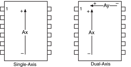
A dual-axis accelerometer detects changes in acceleration and gravity in both the x and
y planes (see Fig. 35-2). If the sensor is mounted vertically—so that the y axis points straight
up and down—the y axis detects up and down changes, and the x axis will detect side-to-side
motion. Conversely, if the sensor is mounted horizontally, the y axis detects motion forward
and backward, and the x axis detects motion from side to side.
Analog Devices is a semiconductor maker primarily for industrial- and military-grade operational
amplifiers, digital-to-analog and analog-to-digital converters, and motion control
products. One of their key product lines is accelerometers, and for them they use a patented
fabrication process to create a series of near-microscopic mechanical beams. This micromachining
involves etching material out of a substrate. During acceleration, the beam is distended
along its length. This distention changes the capacitance in nearby plates. This
change in capacitance is correlated as acceleration.
A thorough discussion of the theory of operation behind the ADXL family of accelerometers
is beyond the scope of this chapter, but you can obtain much more on the subject
directly from the manufacturer. Check the Analog Devices web site at www.analog.com.
In addition to the mechanical portions of the accelerometer, all the basic interface circuitry
is part of the device. In fact, when looking at one of the ADXL accelerometers,
you’d think it was just an integrated circuit of some kind. Because the basic circuitry is
included as part of the accelerometer, only a minimum number of external parts are
needed.
Analog Devices makes a low-cost line of accelerometers specifically designed for consumer
products. Their ADXL202 is a dual-axis device with a ±2-g sensitivity (if you need more g’s,
check out the ADXL210, which is rated at ±10 g’s). Along with being cheaper to buy, the
ADXL202 has a simplified digital output that requires very little hardware interfacing.
Instead of a linear voltage (as is used in other accelerometers), the output is purely digital.
As acceleration changes, the timing of the pulses at the output of the ADXL202 chip
changes. This change can be readily determined by a PC or microcontroller, using simple
software (see the example for the BASIC Stamp 2 later in the chapter).
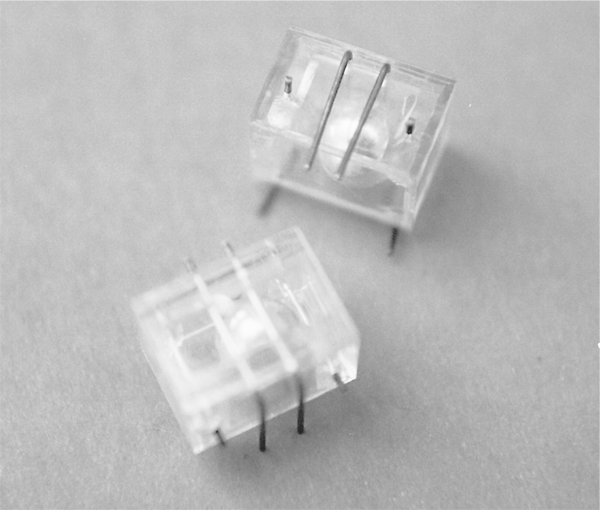
The ADXL202 is a surface-mount component. By a long measure, the ready-made
ADXL202 evaluation board is the easiest way to use this device. It comes on a small
postage-stamp carrier, which can be directly soldered to the BASIC Stamp or other microcontroller.
The basic hookup diagram for the ADXL202 is shown in Fig. 35-3 with the parts list in Table 35-1 Note that except for two filter capacitors and a single resistor, there are no external
components. I have specified a rather low bandwidth of 10 Hz for the device. According to
the ADXL202 data sheet, the value of C1 and C2 for this bandwidth should be 0.47 μ.
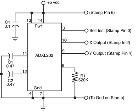
Figure 35-3 A basic schematic diagram for using the Analog
Devices ADXL150 single-axis accelerometer.
IC1 |
ADXL202 acceleration sensor |
R1 |
620k resistor |
C1 |
0.1 μ capacitor |
C2, C3 |
0.47 μ capacitor |
Misc. |
BS2 on development carrier board, PC for programming and interfacing |
Resistor R1 sets the value of the timing pulse used for the output of the x and y axes of
the accelerometer chip. The 620k resistor produces the relatively modest timing pulse of
5 ms; according to the data sheet this requires a nominal value of about 625K for R1. Note
that the exact timing of the pulse is not critical, as any variation will be accounted for in the
software. You will want to select a higher or lower timing pulse based on the capabilities of
the PC or microcontroller you are using and the resolution you desire.
The ADXL202 delivers a PWM with a varying duty cycle. The duty cycle or timing of the
pulses, defined as T2, is set by R1. For this application, the pulses are 5 ms apart. Changes
in acceleration change the width of each pulse. For the ADXL202, the pulse width changes
12.5 percent in each way for each g of acceleration. Therefore, the width of these 5-ms
pulses will change by 50 percent for the entire ±2-g range of the device. A zero g state has
a 50 percent duty cycle, while a 1 g acceleration will have a 25 percent duty cycle (2.5 ms
pulse width) or 75 percent duty cycle (7.5 ms pulse width), depending on the direction of
the acceleration. The period of the PWM signal is defined as T1. Because the ADXL202
uses a pulse width modulated output, rather than a linear DC output, no analog-to-digital
conversion is necessary.
Because the ADXL202 has two axes, it can detect acceleration and gravity changes in two
axes at once. You can use the device in vertical or horizontal orientation. As a tilt sensor,
orient the device horizontally; any tilt in any direction will therefore be sensed. In this position,
the ADXL202 can also be used as a motion detector to determine the speed, direction,
and possibly even the distance (given the resolution of the control circuitry you use) of
that movement.
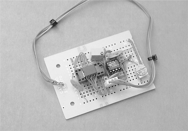
The control interface for the ADXL202 is surprisingly simple. Fig. 35-4 shows the hookup
diagram for connecting the ADXL202 surface-mount chip and evaluation board to a
BASIC Stamp 2. In both cases, power for the ’202 comes from one of the Stamp’s I/O
pins. As mentioned in an application note written by an Analog Devices engineer on the
subject of interfacing the ADXL202 to a BASIC Stamp, this isn’t the overall best design
choice, but for experimenting it’s quick and simple.
The following is a short program written in PBASIC for the BASIC Stamp 2 that allows
continual reading of the two outputs of the ADXL202. The program works by first determining
the period of the T2 basic pulse. It then uses the PULSIN command with both the
T1y and T1x axis signals. PULSIN returns the length of the pulse; a longer pulse means
higher g; a shorter pulse means lower g.
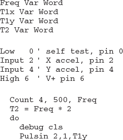
Because the BASIC Stamp 2 has a clock frequency of 2 μs the actual time of the T1y
and T1x pulses are converted to microseconds with the lines
T1y = 2
*T1y
T1x = 2
*T1x T1y and T1x are the pulse widths, in microseconds. These widths are then referenced to
the T2 value previously obtained by the program with the lines
T1y = 8
*T1y / T2
T1x = 8
*T1x / T2 The typical results of this program are numbers like 200 and 170, for the x and y axes,
respectively. Note that even on a flat surface, the two outputs of the ADXL202 may not
exactly match because of manufacturing tolerances.
The do/loop continually reads the outputs of the sensor. Without the Pause statement
and Debug lines, the code loops very fast—just a few tenths of microseconds—which allows
you to insert other programming for your robot. Note that once the loop has begun, the
value of T2 is never read again (unless you restart the entire program). This is acceptable
for low-accuracy applications like basic tilt sensing. But when higher accuracy is required,
the timing of the T2 pulse train should be re-read every 5 or 10 minutes, and even more
frequently if the robot will be subjected to sudden and sharp temperature changes. The output
of the ADXL202 is sensitive to temperature, so changes in temperature will affect the
timing of the T2 pulse.
As the program runs you will note that the value of the x and y outputs will change ±50
to ±75 just by tilting the accelerometer on its sides. Sudden movement of the accelerometer
will produce more drastic changes. Note the values you get and incorporate them into
the accelerometer control software you devise for your robot.
Though the ADXL202 accelerometer is ideally suited for use as a tilt sensor, it has other
uses, too. No additional hardware or even software is required to turn the sensor into a
movement, vibration, and shock sensor. Assuming that the accelerometer is oriented so the
robot travels in the chip’s x axis, then as the robot moves the ADXL202 will register the
change in acceleration.
Should the robot hit a wall or other obstacle, it will be sensed as a very high acceleration/
deceleration spike. Your control software will need to loop through the code at a high
enough rate to catch these momentary changes in output if you want your robot to react to
shocks and vibrations. The do/loop in the previous code repeats often enough that your
robot should detect most collisions with objects.
If you absolutely must detect all collisions you’ll need to devise some kind of hardware
interrupt that will trigger the microprocessor or microcontroller when the output of the
ADXL202 exceeds a certain threshold. Another approach is to dedicate a fast-acting microcontroller
just to the task of monitoring the output of the ADXL202. The low cost of microcontrollers
these days makes such dedicated applications a reasonable alternative.
While factory-made accelerometers, such as the Analog Devices ADXL150 and ADXL202,
are the most convenient for use with robotics, there are some low-cost alternatives you
might want to experiment with. You can make your own home-brew accelerometer using a
50-cent piezo ceramic disc and a heavy steel ball or other weight. The home-brew piezo
accelerometer isn’t as accurate as the ADXL series or other factory-made accelerometers,
but it’ll do in a pinch and teach you about the physics of motion in the process.
The piezo disc accelerometer works by using a well-known behavior of piezoelectric
material: it is both a consumer of energy and a producer of energy. Most applications of
piezoelectric materials are in consumer products like speakers and beepers. Apply a voltage
to the piezoelectric material, and it vibrates, producing a tone. Conversely, if you vibrate the
piezoelectric material using some mechanical means, the output is an electrical signal.
Piezo discs are common finds in electronic and surplus stores. These units are typically
used as the elements in low-cost speakers or tone-makers (like smoke alarms, car alarms,
etc.). The typical piezo disc is about an inch in diameter and is made of brass or some other
nonferrous metal. Deposited on one side of the disc is a ceramic material made of piezo
crystals. These crystals vibrate when a voltage is applied to the disc. Most piezo discs
already have two wire leads conveniently soldered to them so they can be easily connected
to the rest of your circuit.
The disc will be used in electricity-producing mode, with the help of a steel ball or other
heavy weight to provide mechanical energy. Place the ball or weight on the disc—ceramic
side up—and tape the ball in place so it won’t roll or fall off the disc. Connect the output of
the disc to a fast-acting voltage meter or an oscilloscope. Lift the disc up and down rapidly,
and you’ll see the voltage output of the disc fluctuate, perhaps as much as a full volt or two.
The faster you move the disc, the more the voltage will swing.
Just as important as noting the magnitude of the voltage during a change in movement,
note that the polarity of the voltage changes depending on the direction of travel. The output
of the disc might be in positive volts when moving up but negative volts when moving
down.
To complete the construction, mount the disc either on a separate sensor board or on
the robot itself. As an accelerometer that senses lateral motion, the disc can be mounted in
a vertical position, though that will reduce its sensitivity since the ball or weight is being
pulled off the disc by gravity. Be sure that the tape holding the ball is secure. You may wish
to construct a more reliable captive mechanism, perhaps housing the disc and ball or weight
in an enclosure. A 35-mm film can cut to size or a plastic “bug case” (like the kind used for
prizes in bubble gum machines) are good options.
As with a factory-made accelerometer, you can use the piezo disc accelerometer for
vibration and shock detection. Sudden jolts—like when the robot bumps into something—
will translate into larger-than-normal variations in the output of the disc. When you connect
this accelerometer to the brains of your robot, this information can be used to determine
the machine’s proper course of action.
While the piezo disc makes for a cheap and easy accelerometer, it’s not without its limitations.
Here are three you will need to consider:
- The disc will only measure changes in momentum since it is inherently an AC device. Once the momentum of the disc normalizes, the output voltage will fall back to its nominal state. Since gravity acts like a constant DC signal, this means you will not be able to use the piezo disc as a tilt sensor very easily.
- The output of the piezo disc can easily exceed the input voltage of the interfacing electronics. Should the disc receive the blow of a sharp impact, the voltage output can easily exceed 20, 50, and even 100 V. For this reason, you must always place a zener diode to act as a voltage clamp, as shown in Fig. 29-14 of Chapter 29. Select a zener diode voltage that is compatible with the input voltage for the interface you are using. For example, if the interface voltage is 5 vdc, use a 5.1-V zener.
- The piezo disc is basically a capacitor so it stores a charge over time. You can reduce the effects of the capacitive charge by placing a 50K to 250K resistor across the output leads of the disc (this will help to bleed off the charge). You may also want to feed the output of the disc to an op amp.
To learn more about . . . |
Read |
|
Connecting hardware to a computer or microcontroller |
Chapter 29, “Computer Peripherals” |
|
Navigating through an Environment |
Chapter 33, “Navigating through Space” |