NAVIGATION
The projects and discussion in this chapter focus on navigating your robot through
space—not the outerspace kind, but the space between two chairs in your living room,
between your bedroom and the hall bathroom, or outside your home by the pool. Robots
suddenly become useful once they can master their surroundings, and being able to wend
their way through their surrounds is the first step toward that mastery.
The techniques used to provide such navigation are varied: path-track systems, infrared
beacons, ultrasonic rangers, compass bearings, dead reckoning, and more.
A helpful way to look at robot navigation is to think of it as a game, like soccer. The aim of
soccer is for the members of one team to kick the ball into a goal. That goal is guarded by
a member of the other team, so it’s not all that easy to get the ball into the goal. Similarly,
for a robot a lot stands between it and its goal of getting from one place to another. Those
obstacles include humans, chairs, cats, a puddle of water, an electrical cord—just about anything
can prevent a robot from successfully traversing a room or yard.
To go from point A to point B, your robot will consider the following process (as shown
in Fig. 33-1):

Figure 33-1 Navigation through open space requires that the robot
be programmed not only to achieve the "goal" of a specific task but to
self-correct for possible obstacles.
1. Retrieve instruction of goal: get to point B. This can come from an internal condition
(battery is getting low; must get to power recharge station) or from a programmed or
external stimulus.
2. Determine where point B is in relation to current position (point A), and determine a
path to point B. This requires obtaining the current position using known landmarks or
references.
3. Avoid obstacles along the way. If an immovable obstacle is encountered, move around
the obstacle and recalculate the path to get to point B.
4. Correct for errors in navigation ("in-path error correction") caused by such things as
wheel slippage. This can be accomplished by periodically reassessing current position
using known landmarks or references.
5. Optionally, time out (give up) if goal is not reached within a specific period of time or
distance traveled.
Notice the intervening issues that can retard or inhibit the robot from reaching its goal. If
there are any immovable obstacles in the way, the robot must steer around them. This
means its predefined path to get from point A to point B must be recalculated. Position and
navigation errors are normal and are to be expected. You can reduce the effects of error by
having the robot periodically reassess its position. This can be accomplished by using a
number of referencing schemes, such as mapping, active beacons, or landmarks.
People don’t like to admit failure, but a robot is just a machine and doesn’t know (or care)
that it failed to reach its intended destination. You should account for the possibility that the
robot may never get to point B. This can be accomplished by using time-outs, which entails
either determining the maximum reasonable time to accomplish the goal or, better yet, the
maximum reasonable distance that should be traveled to reach the goal.
You can build other fail-safes into the system as well, including a program override if the
robot can no longer reassess its current location using known landmarks or references. In
such a scenario, this could mean its sensors have gone kaput or that the landmarks or references
are no longer functioning or accurate. One course of action is to have the robot
shut down and wait to be bailed out by its human master.
Perhaps the simplest navigation system for mobile robots involves following some predefined
path that’s marked on the ground. The path can be a black or white line painted on a
hard-surfaced floor, a wire buried beneath a carpet, a physical track, or any of several other
methods. This type of robot navigation is used in some factories. Marking the path with
reflective tape is preferred in factories because the track can easily be changed without ripping
up or repainting the floor.
You can readily incorporate a tape-track navigation system in your robot. The line-tracing
feature can be the robot’s only means of semi-intelligent action, or it can be just one
part of a more sophisticated machine. You could, for example, use the tape to help guide a
robot back to its battery charger nest.
With a line-tracing robot, you place a piece of white or reflective tape on the floor. For
the best results, the floor should be hard, like wood, concrete, or linoleum, and not carpeted.
One or more optical sensors are placed on the robot. These sensors incorporate an
infrared LED and an infrared phototransistor. When the transistor turns on it sees the light from the LED reflected off the tape. Obviously, darker floors provide better contrast against
light-colored tape.
In a working robot, mount the LED and phototransistors in a suitable enclosure, as
described more fully in Chapter 30, “Object Detection.” Or, use a commercially available
LED–phototransistor pair (again, see Chapter 30). Mount the detectors on the bottom of
the robot, as shown in
Fig. 33-2, in which two detectors are set apart twice the width of the tape.
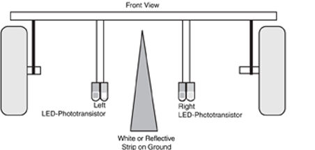
Fig. 33-3 shows the basic sensor circuit and how the LED and phototransistor are wired.
Feel free to experiment with the value of R2; it determines the sensitivity of the phototransistor
and its voltage range when just the floor or the tape is reflecting the infrared light or
a combination of the two. Ideally, you would like the voltage output to be as “binary” as possible:
a high voltage level for a black floor (no light being passed to the phototransistor, so
no current passes through it) and low for the white tape. Fig. 33-4 shows the sensor output
passed to a comparator circuit that forms the basis of the line-tracing system. Refer to this
figure often because this circuit can be used in other applications.
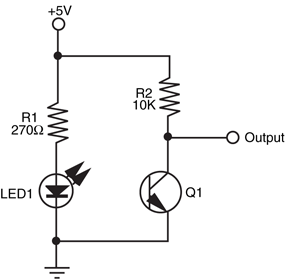
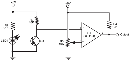
Figure 33-4 Connecting the LED and phototransistor to an LM339 quad comparator
IC. The output of the comparator switches between HIGH and LOW depends on the
amount of light falling on the phototransistor. Note the addition of the 10K pull-up resistor
on the output of the comparator. This is needed to assure proper HIGH/LOW action.
You can use the schematics in Fig. 33-5 and Fig. 33-6 to build a complete line-tracing system
(refer to the parts lists in Tables Table 33-1 and Table 33-2). You can build the circuit using just
three IC packages: an LM339 quad comparator, a 7486 quad exclusive OR gate, and a
7400 quad NAND gate. Before using the robot, block the phototransistors so they don’t
receive any light. Rotate the shaft of the set-point pots until the relays kick in, then back off
again. You may have to experiment with the settings of the set-point pots as you try out the
system.
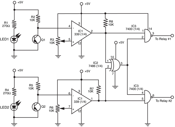
Figure 33-5 Wiring diagram for the line-tracing robot. The outputs of the 7400 are routed to the relays
in Fig. 33-6
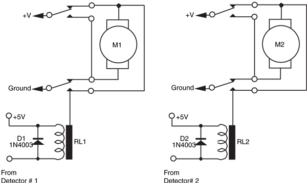
Figure 33-6 Motor direction and control relays for the line-tracing robot. You can substitute the
relays for purely electronic control; refer to Chap. 18.
IC1 |
LM339 quad comparator |
IC2 |
7486 quad exclusive OR gate IC |
IC3 |
7400 quad NAND gate IC |
Q1, Q2 |
Infrared-sensitive phototransistors |
R1, R4 |
270 Ω resistors |
R2, R5, R7, R8 |
10k resistors |
R3, R6 |
10k potentiometers |
LED1, LED2 |
Infrared LEDs |
Misc. |
Infrared filter for phototransistors (if needed) |
RL1, RL2 |
DPDT fast-acting relay; contacts rated 2 A or more |
D1, D2 |
1N4003 diodes |
Depending on which motors you use and the switching speed of the relays, you may find
your robot waddling its way down the track, overcorrecting for its errors every time. You
can help minimize this by using faster-acting relays. Another approach is to vary the gap
between the two sensors. By making it wide, the robot won’t be turning back and forth as
much to correct for small errors.
The actual turn radius will depend entirely on the robot. If you need your robot to turn
very tight, small corners, build it small. If your robot has a brain, whether it is a computer
or central microprocessor, you can use it instead of the direct connection to the relays for
motor control. The output of the comparators, when used with a +5 V supply, is compatible
with computer and microprocessor circuitry, as long as you follow the interface guidelines
provided in Chapter 14. The two sensors require only two bits of an eight-bit port.
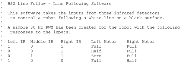
It is quite easy to add and program computer control for a line-following robot. The following
program was written for a three sensor line following robot with the distance between the sensors being about 75 percent of the width of the line—which means that as the line
changes, two sensors are active at any given time, allowing the robot to slow down on that
side rather than turn off the motor completely. Slowing down a side of the robot is accomplished
by decreasing the PWM duty cycle on that side’s motor by 50 percent—you will see
that the turn logic is replicated twice in the following program, with differing values for the
slow turns to run the motors more slowly than if a hard turn is required.
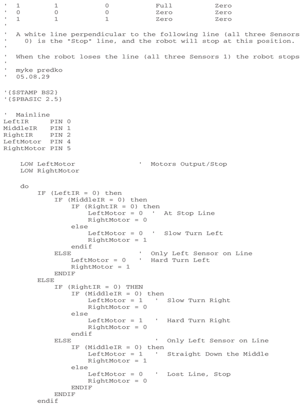
The resulting motion is surprisingly smooth and follows the line very accurately with very
few excursions to the "hard" turn required. To help you see the operation of the robot, you
might want to add some LEDs to the BS2’s I/O pins to "parrot" the IR line sensor inputs
and the motor control outputs.
Robots that can follow walls are similar to those that can trace a line. Like the line, the wall
is used to provide the robot with navigation orientation. One benefit of wall-following robots
is that you can use them without having to paint any lines or lay down tape. Depending on
the robot’s design, the machine can even maneuver around small obstacles (doorstops, door
frame molding, radiator pipes, etc.).
Wall following can be accomplished with any of four methods:
- Contact. The robot uses a mechanical switch, or a stiff wire connected to a switch, to sense contact with the wall, as shown in Fig. 33-7a. This is by far the simplest method, but the switch is prone to mechanical damage over time.
- Noncontact, active sensor. The robot uses active proximity sensors, such as infrared or ultrasonic, to determine its distance from the wall. No physical contact with the wall is needed. In a typical noncontact system, two sensors are used to judge when the robot is parallel to the wall (see Fig. 33-7b).
- Noncontact, passive sensor. The robot uses passive sensors, such as linear Hall effect switches, to judge distance from a specially prepared wall (Fig. 33-7c). In the case of Hall effect switches, you could outfit the baseboard or wall with an electrical wire through which a low-voltage alternating current is fed. When the robot is in the proximity of the switches the sensors will pick up the induced magnetic field provided by the alternating current. Or, if the baseboard is metal, the Hall effect sensor (when rigged with a small magnet on its opposite side) could detect proximity to a wall.
- Soft contact. The robot uses mechanical means to detect contact with the wall, but the contact is softened by using pliable materials. For example, you can use a lightweight foam wheel as a wall roller, as shown in Fig. 33-7d. The benefit of soft contact is that mechanical failure is reduced or eliminated because the contact with the wall is made through an elastic or pliable medium.
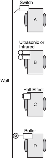
Figure 33-7 Ways to follow the wall include: a. Contact switch;
b. noncontact active sensor (such as infrared); c. noncontact passive
sensor (e.g., Hall effect sensor and magnetic, electromagnetic, or
ferrous metal wall/baseboard); and d. "soft contact" using pliable
material such as foam rollers.
In all cases, upon encountering a wall the robot goes into a controlled program phase to
follow the wall in order to get to its destination. In a simple contact system, the robot may
back up a short moment after touching the wall, then swing in a long arc toward the wall
again. This process is repeated, and the net effect is that the robot "follows the wall."
With the other methods, the preferred approach is for the robot to maintain proper distance
from the wall. Only when proximity to the wall is lost does the robot go into a "find
wall" mode. This entails arcing the robot toward the anticipated direction of the wall. When
contact is made, the robot alters course slightly and starts a new arc. A typical pattern of
movement is shown in
Fig. 33-8.

Figure 33-8 A wall-following robot that merely “feels” its
way around the room might make wide, sweeping arcs. The
arc movement is easily accomplished in a typical two-wheeled
robot by running one motor slower than the other.
A simple ultrasonic wall follower can use two ultrasonic transmitter/receiver pairs. Each
transmitter and receiver is mounted several inches apart to avoid cross-talk. Two transmitter/
receiver pairs are used to help the robot travel parallel to the wall. Suitable ultrasonic transmitter
and receiver circuits are detailed in Chapter 30, "Object Detection."
Because the robot will likely be close to the wall (within a few inches), you will want to
drive the transmitters at very low power and use only moderate amplification, if any, for the
receiver. You can drive the transmitters at very low power by reducing the voltage to the
transmitter.
Soft-contact wall following with a roller wheel offers you some interesting possibilities. In
fact, you may be able to substantially simplify the sensors and control electronics by placing
an idler roller made of soft foam as an outrigger to the robot and then having the robot constantly
steer inward toward the wall. This can be done simply by running the inward wheel
(the wheel on the side of the wall) a little slower than the other. The foam idler roller will prevent
the robot from hitting the wall.
Merely following a wall is, in essence, not that difficult. The task becomes more challenging
when you want the robot to maneuver around obstacles or skip past doorways. This
requires additional sensors, perhaps whiskers or other touch sensors in the forward portion
of the robot. These are used to detect corners as well. This is especially important when you
are constructing a robot that has a simple inward-arc behavior toward following walls.
Without the ability to sense a wall straight ahead, the robot may become hopelessly trapped
in a corner.
Open doorways that lead into other rooms can be sensed using a longer-range ultrasonic
transducer. Here, the long-range ultrasonic detects that the robot is far from any wall and
places the machine in a "go straight" mode. Ideally, the robot should time the duration of
this mode to account for the maximum distance of an open doorway. If a wall is not
detected within x seconds, the robot should go into a "look for wall" mode.
Software for a wall-following robot can be accomplished by using similar software as the
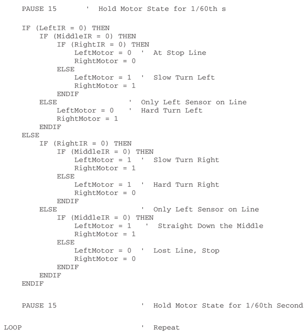
line-following robot; a PWM can be used to make gentle turns, and hard turns can be made when required (such as when a wall is in front of the robot). The following program is optimized
to eliminate some of the decision making for the "slow" versus "hard" turns in the
first 15-ms portion of the PWM operation; in the second part, the decision is made whether
or not to turn the motors off for the full PWM cycle.
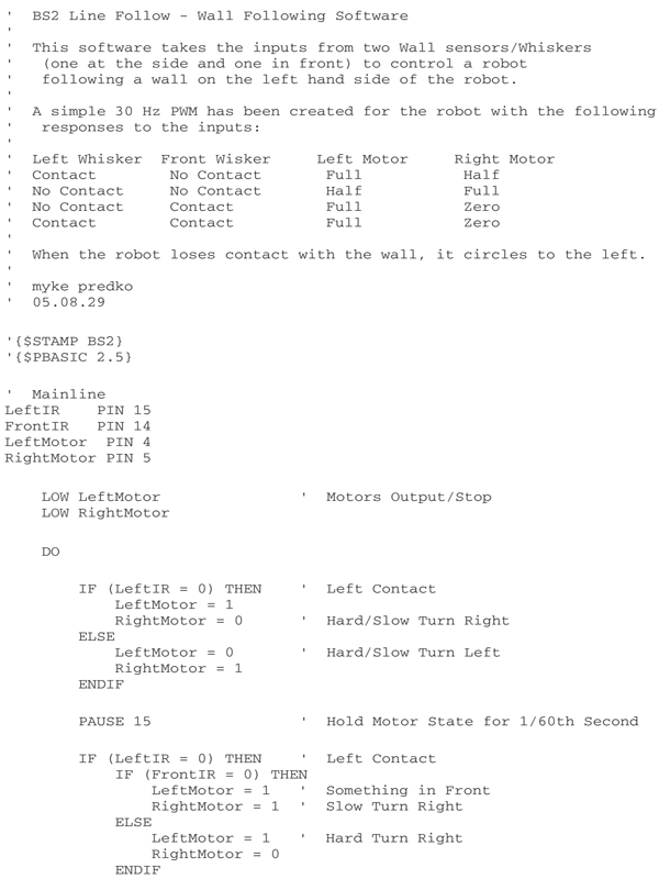

This application was run on the same robot as the line follower, but used Sharp IR object
sensors (see Chapter 30, “Object Detection,” for more information on the sensors).
Hop into your car. Note the reading on the odometer. Now drive straight down the road for
exactly one minute, paying no attention to the speedometer or anything else (of course,
keep your eyes on the road!). Again note the reading on the odometer. The information on
the odometer can be used to tell you where you are. Suppose it says one mile. You know
that if you turn the car around exactly 180° and travel back a mile, at whatever speed, you’ll
reach home again.
This is the essence of odometry; reading the motion of a robot’s wheels to determine
how far it’s gone. Odometry is perhaps the most common method for determining where
a robot is at any given time. It’s cheap, easy to implement, and fairly accurate over short
distances. Odometry is similar to the dead-reckoning navigation used by sea captains and
pilots before the age of satellites, radar, and other electronic schemes. Hence, odometry is
also referred to in robot literature as dead reckoning.
You can use a small disc fashioned around the hub of a drive wheel, or even the shaft of a
drive motor, as an optical shaft encoder (described in “Anatomy of a Shaft Encoder,” in
Chapter 20). The disc can be either the reflectance or the slotted type:
- With a reflectance disc, infrared light strikes the disc and is reflected back to a photodetector.
- With a slotted disc, infrared light is alternately blocked and passed and is picked up on the other side by a photodetector.
With either method, a pulse is generated each time the photodetector senses the light.
You can construct a magnetic encoder using a Hall effect switch (a semiconductor sensitive
to magnetic fields) and one or more magnets. A pulse is generated each time a magnet passes by the Hall effect switch. A variation on the theme uses a metal gear and a special
Hall effect sensor that is sensitive to the variations in the magnetic influence produced by
the gear (see
Fig. 33-9).
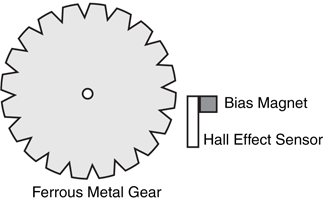
Figure 33-9 A Hall effect sensor outfitted
with a small “bias” magnet and sensitive
to the changes in magnetic flux
caused by a rotating ferrous metal gear.
A bias magnet is placed behind the Hall effect sensor. A pulse is generated each time a
tooth of the gear passes in front of the sensor. The technique provides more pulses on each
revolution of the wheel or motor shaft, and without having to use separate magnets on the
rim of the wheel or wheel shaft.
As the wheel or motor shaft turns, the encoder (optical or magnetic) produces a series of
pulses relative to the distance the robot travels. Assume the wheel is 3 in diameter (9.42 in
in circumference), and the encoder wheel has 32 slots. Each pulse of the encoder represents
0.294 in of travel (9.42/32). If the robot senses 10 pulses, it can calculate the movement
to 2.94 in.
It’s best to make odometry measurements using a microcontroller that is outfitted with a
pulse accumulator or counter input. These kinds of inputs independently count the number
of pulses received since the last time they were reset. To take an odometry reading, you
clear the accumulator or counter and then start the motors. Your software need not monitor
the accumulator or counter. Stop the motors, and then read the value in the accumulator
or counter. Multiply the number of pulses by the known distance of travel for each pulse.
(This will vary depending on the construction of your robot; consider the diameter of the
wheels and the number of pulses of the encoder per revolution.)
If the robot uses the traditional two-wheel-drive approach, you should attach optical
encoders to both wheels. This is necessary because the drive wheels of a robot are bound
to turn at slightly different speeds over time. By integrating the results of both optical
encoders, it’s possible to determine where the robot really is as opposed to where it should
be (see Fig. 33-10). As well, if one wheel rolls over a cord or other small lump, its rotation
will be hindered. This can cause the robot to veer off course, possibly by as much as 3 to 5
degrees or more. Again, the encoders will detect this change.
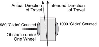
Figure 33-10 The relative number of "counts"
from each encoder of the typical two-wheeled robot
can be used to indicate deviation in travel. If an
encoder shows that one wheel turned a fewer number
of times than the other wheel, then it can be assumed
the robot did not travel in a straight line.
If the number of pulses from both encoders is the same, you can assume that the robot
traveled in a straight line, and you have only to multiply the number of pulses by the distance per pulse. For example, if there are 1055 pulses in the accumulator-counter, and if
each pulse represents 0.294 in of travel, then the robot has moved 310.17 in straight
forward.
In a perfect world, robots would not need anything more than a single odometer to
determine exactly where they were at any given time. Unfortunately, robots live and work
in a world that is far from perfect; as a result, their odometers are far from accurate. Over
a 20- to 30-ft range, for example, it’s not uncommon for the average odometer to misrepresent
the position of the robot by as much as half a foot or more!
Why the discrepancy? First and foremost: wheels slip. As a wheel turns, it is bound to
slip, especially if the surface is hard and smooth, like a kitchen floor. Wheels slip even more
when they turn. The wheel encoder may register a certain number of pulses, but because of
slip the actual distance of travel will be less. Certain robot drive designs are more prone to
error than others. Robots with tracks are steered using slip—lots of it. The encoders will
register pulses, but the robot will not actually be moving in proportion.
There are less subtle reasons for odometry error. If you’re even a hundredth of an inch
off when measuring the diameter of the wheel, the error will be compounded over long distances.
If the robot is equipped with soft or pneumatic wheels, the weight of the robot can
deform the wheels, thereby changing their effective diameter.
Because of odometry errors, it is necessary to combine it with other navigation techniques,
such as active beacons, distance mapping, or landmark recognition. All three are
detailed later in this chapter.
Besides the stars, the magnetic compass has served as humankind's principal navigation aid
over long distances. You know how it works: a needle points to the magnetic North Pole of
the earth. Once you know which way is north, you can more easily reorient yourself in your
travels.
Robots can use compasses as well, and a number of electronic and electromechanical
compasses are available for use in hobby robots. One of the least expensive is the Dinsmore
1490, from Dinsmore Instrument Co. The 1490 looks like an overfed transistor, with 12
leads protruding from its underside. The leads are in four groups of three; each group represents
a major compass heading: north, south, east, and west. The three leads in each
group are for power, ground, and signal. A Dinsmore 1490, mounted on a circuit board, is
shown in
Fig. 33-11.
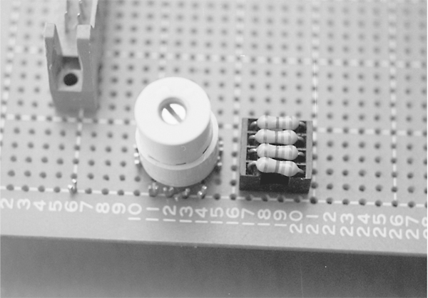
Figure 33-11 The Dinsmore 1490 digital compass provides simple bearings for a robot. The
sensor is accurate to about 45 degrees.
The 1490 provides eight directions of heading information (N, S, E, W, SE, SW, NE,
NW) by measuring the earth’s magnetic field. It does this by using miniature Hall effect sensors
and a rotating compass needle (similar to ordinary compasses). The sensor is said to be
internally designed to respond to directional changes much like a liquid-filled compass. It
turns to the indicated direction from a 90° displacement in approximately 2.5 s. The manufacturer's
specification sheet claims that the unit can operate with up to 12 degrees of tilt
with acceptable error, but it is important to note that any tilting from center will cause a corresponding
loss in accuracy.
Fig. 33-12 shows the circuit diagram for the 1490, which uses four inputs to a computer
or microcontroller. Note the use of pull-up resistors. With this setup, your robot can determine
its orientation with an accuracy of about 45 degrees (less if the 1490 compass is tilted).
Dinsmore also makes an analog-output compass that exhibits better accuracy.
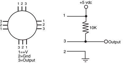
Figure 33-12 Circuit diagram for using the Dinsmore 1490
digital compass. When used with a +5 vdc supply, the four outputs
can be connected directly to a microcontroller. One or two
outputs can be activated at a time; if two are activated, the sensor
is reading between the four compass points (e.g., N and W
outputs denotes NW position).
You could also consider the Vector 2X and 2XG. These units use magneto-inductive sensors for sensing magnetic fields. The Vector 2X/2XG provides either compass heading or
uncalibrated magnetic field data. This information is output via a three-wire serial format
and is compatible with Motorola SPI and National Semiconductor Microwire interface standards.
Position data can be provided either 2.5 or 5 times per second.
Vector claims accuracy of ±2 degrees. The 2X is meant to be used in level applications.
The more pricey 2XG has a built-in gimbal mechanism that keeps the active magnetic-inductive
element level, even when the rest of the unit is tilted. The gimbal allows tilt up to
12 degrees.
A final option to consider is a commercially available GPS unit with a built-in compass
and RS-232 serial interface like a Garmin "ETrex" line of outdoor GPS units. RS-232 data
are normally sent as a "NMEA" data stream, which can be easily filtered by a microcontroller
like a BS2. A handheld GPS unit usually has a very accurate compass built into the
unit (to a degree or less) and is very insensitive to tilting. The only downside to using a handheld
GPS unit is the price—they can often be several hundred dollars.
Police radar systems work by sending out a high-frequency radio beam that is reflected off
nearby objects, such as your car as you are speeding down the road. Most people believe
that the speed is calculated by timing how long it takes for a signal sent from the radar gun
to bounce off the car and return; multiple "shots" are timed and the speed is calculated
based on the rate of change in the return time of these pulses. Speed is actually calculated
using the Doppler effect: the frequency of the reflected signal varies according to how fast
you are going and whether you are approaching or going away from the radar unit.
Radar systems are complex and expensive, and most require certification by a government
authority, such as the Federal Communications Commission for devices used in the United States. There is another approach: you can use high-frequency sound instead to
measure distance, and with the right circuitry you can even provide a rough indication of
speed.
Ultrasonic ranging is, by now, an old science. Polaroid used it for years as an automatic
focusing aid on their instant cameras. Other camera manufacturers have used a similar
technique, though it is now more common to implement infrared ranging (covered later in
the chapter). The Doppler effect that is caused when something moves toward or away
from the ultrasonic unit is used in home burglar alarm systems. However, for robotics the
more typical application of ultrasonic sound is either to detect proximity to an object (see
"Ultrasonic Wall Following," earlier in the chapter) or to measure distance (also called ultrasonic
ranging).
To measure distance, a short burst of ultrasonic sound—usually at a frequency of 40 kHz
for most ultrasonic ranging systems—is sent out through a transducer (a specially built ultrasonic
speaker). The sound bounces off an object, and the echo is received by another transducer
(this one a specially built ultrasonic microphone). A circuit then computes the time it
took between the transmit pulse and the echo and comes up with distance.
Certainly, the popularity of ultrasonics does not detract from its usefulness in robot
design. The system presented here is suited for use with a computer or microcontroller.
There are a variety of ways to implement ultrasonic ranging. One method is to use the
ultrasonic transducer and driver board from an old Polaroid instant camera, such as the
Polaroid Sun 660 or the Polaroid SX-70 One Step. However, the driver board used in
these cameras may require some modification to allow more than one "ping" of ultrasonic
sound without having to cycle the power to the board off, then back on. More about this
in a bit. You can also purchase a new Polaroid ultrasonic transducer and driver board from
a number of mail-order sources, including on the Internet. Several of these outlets are
listed in Appendix B, "Sources." These units are new, and most come with documentation,
including hookup instructions for connecting to popular microcontrollers, such as the
BASIC Stamp. Perhaps the most common Polaroid distance-measuring kit is composed of
the so-called 600 Series Instrument Grade transducer along with its associated Model
6500 Ranging Module (
Fig. 33-13).
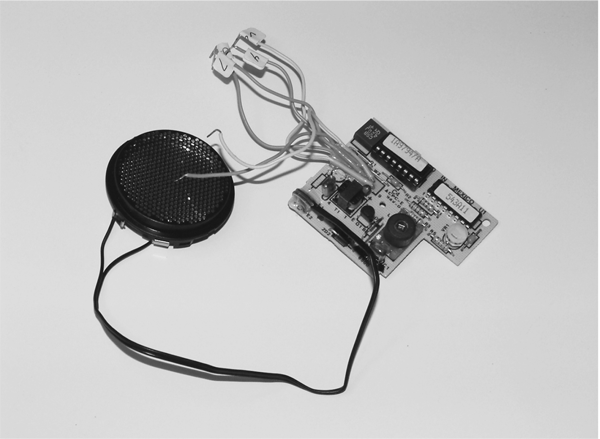
Figure 33-13 Polaroid 6500 module with wires attached to simplify adding the circuit to a
robot. Note that 1 A of current is required and to minimize noise in the rest of the circuit, a 1000 μF
capacitor is placed across the Polaroid 6500’s power leads.
The transducer, which is about the size of a silver dollar coin, acts as both ultrasonic
transmitter and receiver. Because only a single transducer is used, the Polaroid system as
described in this section cannot detect objects closer than about 1.3 ft. This is because of
the amount of time required for the transducer to stop oscillating before it sets itself up to
receive. The maximum distance of the sensor is about 35 ft when used indoors, and a little
less when used outdoors, especially on a windy day. The system is powered by a single 6-vdc
battery pack and can be interfaced to any computer or microcontroller.
First some statistics. At sea level, sound travels at a speed of about 1130 f/s (about 344
m/s) or 13,560 in/s. While this time varies depending on atmospheric conditions, including
air pressure (which varies by altitude), temperature, and humidity, it is a good value to
use when working with an ultrasonic ranging system. The overall time between transmit
pulse and echo is divided by two to compensate for the round-trip travel time between the
robot and the object. Given a travel time of 13,560 in/s for sound, it takes just 73.7 μ (0.0000737 s) for sound to travel 1 in. This means that for every 147.4 μs of time, the distance
between the transducer and an object changes by 1 in (2.5 cm).
With the figure of 1 in per 147.4 μ in the back of our minds, let's consider how the
Polaroid ranging system works. The Ranging Module is connected to a computer or microcontroller
using only two wires: INIT (for INITiate) and ECHO. INIT is an output, and ECHO
is an input. The Ranging Module contains other I/O connections, such as BLNK and BINH,
but these are not strictly required when you are determining distance to a single object, and
so they will not be discussed here.
To trigger the Ranging Module and have it send out a burst of ultrasonic sound, the computer
or microcontroller brings the INIT line HIGH. The computer-microcontroller then
waits for the ECHO line to change from LOW to HIGH. The time difference, in microseconds,
is divided in two, and that gives you distance. To measure the time between the INIT
pulse and the return ECHO, the computer or microcontroller uses a timer to precisely count
the time interval.
To demonstrate the operation of the Polaroid 6500 with a BS2, some additional circuitry
has to be added as shown in
Fig. 33-14 (parts list in Table 33-3). The 74LS123 and 74LS74 create a delayed pulse that can be measured by a BASIC Stamp 2's Pulsin statement.
Using one of the single 74LS123 monostable multivibrator's single-shot outputs creates
two D-flip flop triggering pulses that ensure that the resulting pulse passed to the BS2
has the same timing as the delay between the initialization of the Init and the Echo return
as shown in Fig. 33-15.
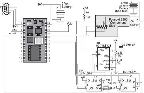
Figure 33-14 Polaroid 6500 module connected to a BS2 using a monostable multivibrator and
two D-flip flops to ensure the waveform passed to the BS2 is a pulse and available when the BS2 is
ready for it.
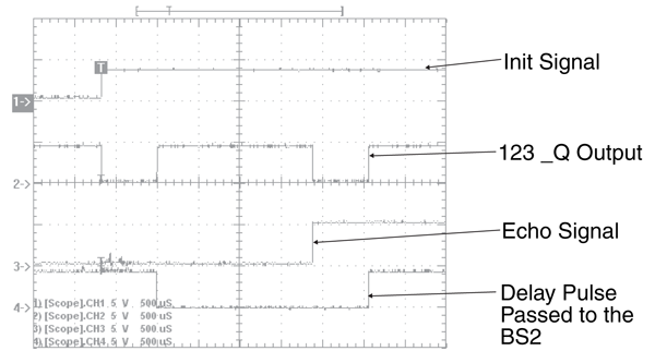
Figure 33-15 Operation of the BS2 Polaroid 6500 module interface. Note that the Init signal causes the
74LS123 to trigger, starting a pulse output on the 74LS74 to be measured by the BS2. When the echo has
returned, the 74LS123 is triggered again, changing the state of the 74LS74 and completing the pulse.
BS2 |
Parallax BS2 |
Polaroid 6500 |
Polaroid 6500 ranging module with wires attached for breadboard
interfacing |
IC1 |
74LS123 dual monostable multivibrator chip |
IC2 |
74LS74 dual D-flip flop chip |
R1 |
10k resistor |
R2 |
2.2k resistor |
C1, C2 |
0.1 μF capacitor |
C3, C4 |
0.01 μF capacitor |
C5 |
1 μF capacitor |
C6 |
1000 μF capacitor (see text) |
Misc. |
Breadboard, BS2 communication/programming interface, 9-V battery,
6-V lantern battery (see text) |
It is important to note that the Polaroid 6500 uses a massive amount of current when it
is operating. To ensure that the BS2 and the TTL chips’ operation are not affected by the
6500, the 6500 is given a power supply separate from the other chips. For the prototype
circuit, a 6-V lantern battery was used for powering the 6500. The BS2’s on-board regulator
is used to power both it as well as the two TTL chips.
When the 6500 is active, make sure the transducer is mounted on a nonconducting surface
and you are not touching it! The 6500 will give you a nasty shock when it is active and
could potentially damage any electronics that have common pins to it.
The software to use the BS2/Polaroid 6500 combination follows and consists of resetting
the 74LS74 D-flip flops before sending out the Init signal and waiting for the delayed
pulse back.
'BS2 Polaroid 6500 - Use Polaroid 6500 Sonar Ranging Module''myke predko''04.01.25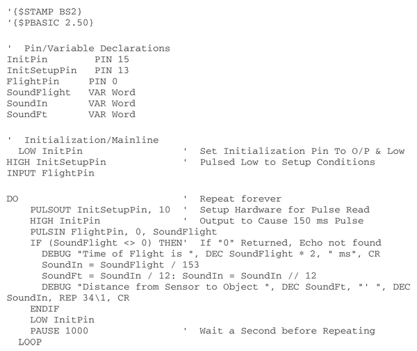
Explorers rely on landmarks to navigate wide-open areas. It might be an unusual outcropping
of rocks or a bend in a river. Or the 7-Eleven down the street. In all cases, a landmark
serves to give you general bearings. From these general bearings you can more readily navigate
a given locale.
Robots can use the same techniques, though rocks, rivers, and convenience stores are
somewhat atypical as useful landmarks. Instead, robots can use such techniques as beacons
to determine their absolute position within a known area. The following sections describe
some techniques you may wish to consider for your next robot project.
Unless you confine your robot to playing just within the laboratory, you'll probably want to
provide it with a means to distinguish one room in your house from the next. This is particularly
important if you’ve designed the robot with even a rudimentary form of object and
area mapping. This mapping can be stored in the robot’s memory and used to steer around
objects and avoid walls.
For less than a week's worth of groceries, you can construct an infrared beacon system that your robot can use to determine when it has passed from one room to the next. The
robot is equipped with a receiver that will detect transmitters placed in each room. These
transmitters send out a unique code, which the robot interprets as a specific room. Once it
has identified the room, it can retrieve the mapping information previously stored for it and
use it to navigate through its surroundings.
The beacon system presented here is designed around a set of television and VCR
remote control chips sold by Holtek. The chips are reasonably inexpensive but can be difficult
to find. The chips used in this project are HT12D and HT12E, available from Jameco
(www.jameco.com, but you should check the Internet for other sources as well).
You can, of course, use just about any wireless remote control system you desire. The
only requirements are that you must be able to set up different codes for each transmitter
and that the system must work with infrared light.
You can connect the four-bit output of the HT-12D decoder IC to a microcontroller or
computer. You will also want to connect the VD (valid data) line to a pin of your microcontroller
or computer. When this line "winks" LOW, it means there is valid data on the four
data lines. The value at the four data lines will coincide with the setting of the four-position
DIP switch on each transmitter.
Radio frequency identification (RFID) is a hot technology that uses small passive devices that
radiate a digital signature when exposed to a radio frequency signal. RFID is found in products
ranging from toys to trucking, farm animal inventories, automobile manufacturing, and
more, including replacing the bar codes used at retail checkouts.
A transmitter/receiver, called the interrogator or reader, radiates a low- or medium-frequency
carrier RF signal. If it is within range, a passive (unpowered) or active (powered)
detector, called a tag or transponder, re-radiates (or backscatters) the carrier frequency,
along with a digital signature that uniquely identifies the device. RFID systems in use today
operate on several common RF bands, including a low-speed 100 to 150 kHz band and a
higher 13.5 MHz band.
The tag is composed of an antenna coil along with an integrated circuit. The radio signal
provides power when used with passive tags, using well-known RF field induction principles.
Inside the integrated circuit are decoding electronics and a small memory. A variety
of data transmission schemes are used, including non-return-to-zero, frequency shift keying,
and phase shift keying. Manufacturers of the RFID devices tend to favor one system over
another for specific applications. Some data modulation schemes are better at long distances,
for example.
Different RFID tags have different amounts of memory, but a common device might provide
for 64 to 128 bits of data. This is more than enough to serve as room-by-room or
locale-by-locale beacons. The advantage RFID has over infrared beacons (see earlier in this
chapter) is that the coverage of the RF signal is naturally limited. While this limitation can
certainly be a disadvantage, when properly deployed it can serve as a convenient way to differentiate
between different areas of a house’s robotic work space. The average working
distance between interrogator and tag is several feet, though this varies greatly depending
on the power output of the interrogator. Units with higher RF power can be used over
longer distances. For room-by-room robotics use, however, a unit with limited range is preferred,
which also means a less expensive system.
While RFID systems are not complex, their cost can be a bit expensive for hobbyists.
Demonstration and developers' kits are available from some manufacturers for $100 to
$200, and this includes the reader and an assortment of tags. However, once implemented
RFID is a low-maintenance, long-term solution for helping your robot know where it is.
As mentioned, humans navigate the real world by using landmarks: the red barn on the way
to work signals you're getting close to your turnoff. Robots can use the same kind of visual
cues to help them navigate a space. Landmarks can be natural—a support pillar in a warehouse
for example—or they can be artificial—reflectors, posts, or bar codes positioned just
for use by the robot. A key benefit of landmark recognition is that most systems are easy to
install, cheap, and when done properly, unmistakable from the robot’s point of view.
Wide Field Bar Code One technique to consider is the use of wide-field bar codes,
which are commonly used in warehouses for quick and easy inventory. The bar code pattern
is printed very large, perhaps as tall as 2 in and as wide as a foot. A traditional laser
bar code reader then scans the code. The large size of the bar code makes it possible to use
the bar code reader even from a distance—10 to 20 ft or more.
You can adapt the same method to help your robot navigate from room to room, and
even within a room. For each location you want to identify, print up a large bar code. Free
and low-cost bar code printing software is available over the Internet and in several commercial
packages. You can either make or purchase a wide-field bar code scanner and connect
it to your robot’s computer or microcontroller. As your robot roams about, the scanner
can be constantly looking for bar codes. The laser light output from the scanner is very low
and, if properly manufactured, is well within safe limits even if the beam should quickly scan
past the eyes of people or animals.
Door Frame "Flags" Yet another technique that merits consideration is the use of
reflective tape placed around the frames of doors. Doorways are uniquely helpful in robot
navigation because in the human world we tend to leave the space around them open and
uncluttered. This allows us to enter and exit a room without tripping over something. It also
typically means that the line of sight of the door will not be blocked, creating a reliable landmark
for a robot.
Imagine vertical strips of reflective tape on either side of the doorway. These strips could
reflect the light from a scanning laser mounted on the robot, as shown in
Fig. 33-16. The
laser light would be reflected from the tape and received by a sensor on the robot. Since the
speed of the laser scan is known, the timing between the return pulses of the reflected laser
light would indicate the relative distance between the robot and the doorway. You could use
additional tape strips to reduce the ambiguity that results when the robot approaches the
doorway at an angle.
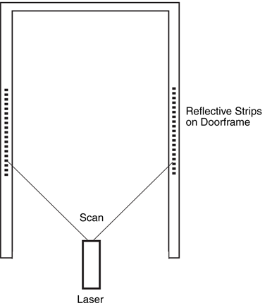
Figure 33-16 A scanning laser mounted on your
robot can be used to detect the patterns of reflective tape
located on or near doorways. Since the speed of the scan
is known, electronics on your robot calculate distance (and
position, given more strips) from robot to door.
Or consider using a CCD or CMOS camera. The robot could use several high-output
infrared LEDs to illuminate the tape strips. Since the tape is much more reflective than the
walls or door frame, it returns the most light. The CCD or CMOS camera is set with a high
contrast ratio, so it effectively ignores anything but the bright tapes. Assuming the robot is
positioned straight ahead of the door, the tapes will appear to be parallel. The distance
between the tapes indicates the distance between the robot and the doorway. Should the robot be at an angle to the door, the tapes will not be parallel. Their angle, distance, and
position can once again be interpolated to provide the robot’s position relative to the door.
There are scores of ways to relay position information to a robot. You've already seen two
beacon-type systems: infrared and radio frequency. There are plenty more. There isn't
enough space in this book to discuss them all, but the following sections outline some techniques
you might want to consider. Many of these systems rely on a line of sight between
the beacon or lighthouse and the robot. If the line of sight is broken, the robot may very well
get lost.
Three-Point Triangulation Traditional three-point triangulation is possible using
either of two methods:
- Active beacon. A sensor array on the robot determines its location by integrating the relative brightness of the light from three active light sources.
- Active robot. The robot sends out a signal that is received by three sensors located around the room. The sensors integrate the robot's position, then relay this information back to the robot (via RF or an infrared radio link).
This technique calculates time of flight using sound, and it offers excellent accuracy. You
equip three active beacons with sonar transmitters and high-output infrared light-emitting
diodes. You then connect the three beacons electrically so they will fire in sequence. When
fired, both the sonar transmitter and IR LEDs emit a short 40 kHz signal. Because light travels
much faster than sound, the robot will detect the IR signal first, followed by the sound
signal.
The difference in time between the reception of the IR and sound signals represents distance.
Each beacon provides a circle path that the robot can be in. All three circles will
intersect at only one spot in the room, and that will be the location of the robot. See
Fig. 33-17 for a demonstration of how this works.
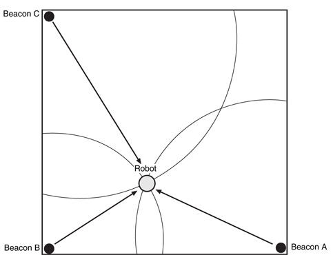
Figure 33-17 Three active beacons, connected to fire in sequence, provide
both infrared and ultrasonic sound signals. Using a burst of infrared light,
the robot times how long it takes for the sonar ping to reach it. Repeated three
times—one for each beacon—the robot is able to make an accurate fix within
the room.
Over the years a number of worthwhile techniques have been developed to help robots
know where they are. We've covered many of the most common techniques here. If your budget and construction skills allow for it, however, you might want to consider any or all of
the following.
Hovering over the earth are some two dozen satellites that provide accurate world-positioning
data to vehicles, ships, and aircraft. The satellite network, referred to as global
positioning system (GPS), works by triangulation: the signals from three or more satellites
are received and their timings are compared. The difference in the timings indicates the relative
distances between the satellites and the receiver. This provides a “fix” by which the
receiver can determine not only the latitude and longitude most anywhere on the earth, but
also elevation.
GPS was primarily developed by the United States government for various defense systems,
but it is also regularly used by private commerce and even consumers. Until recently,
the signals received by a consumer-level GPS receiver have been intentionally “fuzzied” to
decrease the accuracy of the device. (This is called selective availability, imposed by the
U.S. government for national security reasons.) Instead of the accuracies of a few feet or
less that are possible with military-grade GPS receivers, consumer GPS receivers have had
a nominal resolution of 100 m, or about 325 ft. In practical use, with selective availability
activated in the GPS satellites, the actual error is typically 50 to 100 ft. Selective availability
has since been deactivated (but could be re-activated in the event of a national emergency),
and the resolution of consumer GPS receivers can be under 20 to 25 ft.
Furthermore, a system called differential GPS, in which the satellite signals are correlated
with a second known reference, demonstrably increases the resolution of GPS signals
to less than 5 in. When used outdoors (the signal from the satellites is too weak for indoor
use), this can provide your robot with highly accurate positioning information, especially if
your ’bot wanders hundreds of feet from its base station. Real-time differential GPS systems
are still fairly costly, but their outputs can read into the robot’s computer in real time. It
takes from one to three minutes for the GPS system to lock onto the satellites overhead,
however. Every time the lock is broken—the satellite signals are blocked or otherwise lost—
it takes another one to three minutes to reestablish a fix.
If you’re interested in experimenting with GPS, look for a receiver that has a NMEA-
0183 or RS-232 compatible computer interface. A number of amateur radio sites on the
Internet discuss how to use software to interpret the signals from a GPS receiver.
You can use the same physics that keeps a bicycle upright when its wheels are in motion to
provide motion data to a robot. Consider a bicycle wheel spinning in front of you while you
hold the axle between your hands. Turn sideways and the wheel tilts. This is the gyroscopic
effect in action; the angle of the wheel is directly proportional to the amount and time you
are turning. Put a gyroscope in an airplane or ship and you can record even imperceptible
changes in movement, assuming you are using a precision gyroscope.
Gyros are still used in airplanes today, even with radar, ground controllers, and radios to
guide their way. While many modern aircraft have substituted mechanical gyros with completely
electronic ones, the concept is the same. During flight, any changes in direction are recorded by the inertial guidance system in the plane (there are three gyros, for all three
axes). At any time during the flight the course of the plane can be scrutinized by looking at
the output of the gyroscopes.
Inertial guidance systems for planes, ships, missiles, and other such devices are far, far
too expensive for robots. However, there are some low-cost gyros that provide modest
accuracies. One reasonably affordable model is the Max Products MX-9100 micro piezo
gyro, often used in model helicopters. The MX-9100 uses a piezoelectric transducer to
sense motion. This motion is converted into a digital signal whose duty cycle changes in
proportion to the rate of change in the gyro.
Laser- and fiber-optic-based gyroscopes offer another navigational possibility, though
the price for ready-made systems is still out of the reach of most hobby robot enthusiasts.
These devices use interferometry—the subtle changes in the measured wavelength of a light
source that travels in opposite directions around the circumference of the gyroscope. The
light is recombined onto a photosensor or a photocell array such as a CCD camera. In the
traditional laser-based gyroscopes (e.g., the Honeywell ring gyro), the two light beams create
a bull’s-eye pattern that is analyzed by a computer. In simpler fiber-optic systems, the
light beams are mixed and received by a single phototransistor. The wave patterns of the
laser light produce sum and difference signals (heterodyning). The difference signals are well
within audio frequency ranges, and these can be interpreted using a simple frequency-to-voltage
converter. From there, relative motion can be calculated.
A low-cost method to experiment with inertial navigation is to use accelerometers (similar
to those described in detail in Chapter 35, “Experimenting with Tilt and Gravity Sensors”).
The nature of accelerometers, particularly the less-expensive piezoelectric variety,
can make them difficult to employ in an inertial system. Accelerometers are sensitive to the
earth’s gravity, and tilting on the part of the robot can introduce errors. By using multiple
accelerometers—one to measure movement of the robot and one to determine tilt—it is
generally possible to reduce (but perhaps not eliminate) these errors.
Maps help us navigate strange towns and roads. By correlating what we see out the windshield
with the street names on the map, we can readily determine where we are—or just
how lost we are! Likewise, given a map of its environment, a robot could use its various sensors
to correlate its position with the information in a map. Map-based positioning, also
known as map matching, uses a map you prepare for the robot or that the robot prepares
for itself.
During navigation, the robot uses whatever sensors it has at its disposal (infrared, ultrasonic,
vision, etc.) to visualize its environment. It checks the results of its sensors against the
map previously stored in its memory. From there, it can compute its actual position and orientation.
One common technique, developed by robot pioneer Hans Moravec, uses a “certainty
grid” that consists of squares drawn inside the mapped environment (think of graph
paper used in school). Objects, including obstacles, are placed within the squares. The robot
can use this grid map to determine its location by attempting to match what it sees through
its sensors with the patterns on the map.
Obviously, map matching requires that a map of the robot's environment be created first.
Several consumer robots, like the Cyebot, are designed to do this mapping autonomously by exploring the environment over a period of time. Industrial robots typically require that
the map be created using a CAD program and the structure and objects within it very accurately
rendered. The introduction of new objects into the environment can drastically
decrease the accuracy of map matching, however. The robot may mistake a car for a foot
stool, for example, and seriously misjudge its location.
To learn more about . . . |
Read |
|
Using computers and microcontrollers in your robots |
Chapter 14, "Computer Peripherals" |
|
Infrared and wireless communications techniques |
Chapter 16,"Remote Control Systems" |
|
Keeping your robot from crashing into things |
Chapter 30, "Object Detection" |
|
Vision for your robot |
Chapter 32, "Robot Vision" |
|
Preventing your robot from falling over |
Chapter 35, "Experimenting with Tilt and Gravity
Sensors" |