ROBOT VISION
Robotic vision systems can be simple or complex to match your specific requirements
and your itch to tinker. Rudimentary Cyclops vision systems are used to detect nothing
more than the presence or absence of light. Aside from this rather mundane task, there are
plenty of useful applications for an on/off light detector. More advanced vision systems
decode relative intensities of light and can even make out patterns and crude shapes.
While the hardware for making robot eyes is rather simple, using the vision information
they generate is not. Except for the one-cell light detector, vision systems must be interfaced
to a computer to be useful. You can adapt the designs presented in this chapter to just about
any computer using a microprocessor data bus or one or more parallel printer ports.
A number of simple electronic devices can be used as eyes for your robot. These include the
following:
- Photoresistors. These are typically a cadmium-sulfide (CdS) cell (often referred to simply as a photocell). A CdS cell acts like a light-dependent resistor (also referred to as an LDR): the resistance of the cell varies depending on the intensity of the light striking it. When no light strikes the cell, the device exhibits very high resistance, typically in the high 100 kilohms, or even megohms. Light reduces the resistance, usually significantly (a few hundreds or thousands of ohms). CdS cells are very easy to interface to other electronics, but they react somewhat slowly and are unable to discern when the light level changes more than 20 or 30 times per second. This trait actually comes in handy because it means CdS cells basically ignore the on/off flashes of AC-operated lights.
- Phototransistors. These are very much like regular transistors with their metal or plastic tops removed. A glass or plastic cover protects the delicate transistor substrate inside. Unlike CdS cells, phototransistors act very quickly and are able to sense tens of thousands of changes in light level per second. The output of a phototransistor is not linear; that is, there is a disproportionate change in the output of a phototransistor as more and more light strikes it. A phototransistor can become easily swamped with too much light. In this condition, even as more light shines on the device, the phototransistor is not able to detect any change.
- Photodiodes. These are the simpler diode versions of phototransistors. Like phototransistors, they are made with a glass or plastic cover to protect the semiconductor material inside them. And like phototransistors, photodiodes act very fast and can become swamped when exposed to a certain threshold of light. One common characteristic of most photodiodes is that their output is rather low, even when fully exposed to bright light. This means that to be effective the output of the photodiode must usually be connected to a small amplifier.
Photoresistors, photodiodes, and phototransistors are connected to other electronics in
about the same way: you place a resistor between the device and either +V or ground. The
point between the device and the resistor is the output, as shown in Fig. 32-1. With this
arrangement, all three devices therefore output a varying voltage. The exact arrangement
of the connection determines if the voltage output increases or decreases when more light
strikes the sensor.
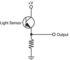
Figure 32-1 The basic connection scheme for phototransistors,
photodiodes, and photoresistors uses a discrete
resistor to form a voltage divider. The output is a
varying voltage, which can go from 0 to +V depending
on the sensor.
Light-sensitive devices differ in their spectral response, which is the span of the visible
and near-infrared light region of the electromagnetic spectrum that they are most sensitive
to. CdS cells exhibit a spectral response very close to that of the human eye, with the greatest
degree of sensitivity in the green or yellow-green region (see Fig. 32-2). Both phototransistors
and photodiodes have peak spectral responses in the infrared and near-infrared
regions. In addition, some phototransistors and photodiodes incorporate optical filtration to
decrease their sensitivity to the visible light spectrum. This filtration makes the sensors more
sensitive to infrared and near-infrared light.
Figure 32-2 Light sensors vary in their sensitivity to different colors of the electromagnetic
spectrum. The color sensitivity of CdS cells is very similar to that of the human eye.
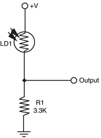
A single light-sensitive photocell is all your robot needs to sense the presence of light. The
photocell is a variable resistor that works much like a potentiometer but has no control
shaft. You vary its resistance by increasing or decreasing the light. Connect the photocell as
shown in Fig. 32-3. Note that, as explained in the previous section, a resistor is placed in
series with the photocell and that the output tap is between the cell and resistor. This converts
the output of the photocell from resistance to voltage, the latter of which is easier to
use in a practical circuit. The value of the resistor is given at 3.3K Ω but is open to experimentation.
You can vary the sensitivity of the cell by substituting a higher or lower value.
For experimental purposes, connect a 1K resistor in series with a 50K pot (in place of the
3.3K Ω resistor) and try using the cell at various settings of the wiper. Test the cell output
by connecting a volt-ohm meter to the ground and output terminals.
So far, you have a nice light-to-voltage sensor, and when you think about it there are
numerous ways to interface this ultrasimple circuit to a robot. One way is to connect the
output of the sensor to the input of a comparator. (The LM339 quad comparator IC is a
good choice, but you can use just about any comparator.) The output of the comparator
changes state when the voltage at its input goes beyond or below a certain trip point. In the
circuit shown in Fig. 32-4 (refer to the parts list in Table. 32-1), the comparator is hooked
up so the noninverting input serves as a voltage reference. Adjust the potentiometer to set
the trip point (or voltage threshold) by first setting it at the midway point and then adjusting
the trip point higher or lower as required. The output of the photocell voltage divider
circuit is connected to the inverting input of the comparator, which will change. When the
photocell voltage divider voltage passes through the threshold voltage, then output of the
comparator changes state.
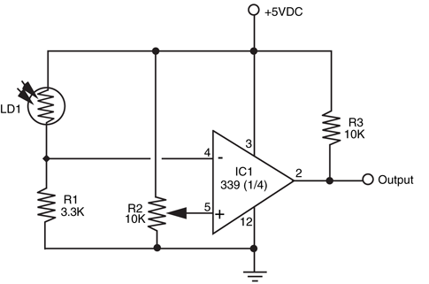
IC1 |
LM339 quad comparator IC |
R1 |
3.3K resistor |
R2 |
10K potentiometer |
R3 |
10K resistor |
LD1 |
Photocell |
One practical application of this circuit is to detect light levels that are higher than the
ambient light in the room. Doing so enables your robot to ignore the background light level
and respond only to the higher intensity light. To begin, set the trip point potentiometer so
the circuit just switches HIGH. Use a flashlight to focus a beam directly onto the photocell,
and watch the output of the comparator change state. Another application is to use the
photocell as a light detector. Set the potentiometer to one extreme so the comparator
changes state just after light is applied to the surface of the cell.
The human eye has millions of tiny light receptacles. Combined, these receptacles allow us
to discern shapes, to actually see rather than just detect light levels. A crude but surprisingly
useful approximation of human sight is given in Fig. 32-5 (refer to the parts list in Table 32-2). Here, eight photocells are connected to a 16-channel multiplexed analog-to-digital
converter (ADC). The ADC, which has enough pins for another eight cells, converts the
analog voltages from the outputs of each photocell and one by one converts them into digital
data. The eight-bit binary number presented at the output of the ADC represents any of
256 different light levels.
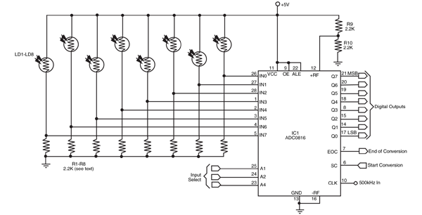
Figure 32-5 One way to make a robotic eye. The circuit, as shown, consists of eight photocells connected to an ADC0816 eight-bit, 16-input
analog-to-digital converter IC. The output of each photocell is converted when selected at the Input Select lines. The ADC0816 can handle up to 16
inputs, so you can add another eight cells.
IC1 |
ADC0816 eight-bit analog-to-digital converter IC |
R1–R8 |
2.2K resistor (adjust value to gain best response of photocells) |
R9, R10 |
2.2K resistors |
LD1–LD8 |
Photocell |
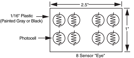
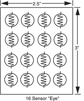
The converter is hooked up in such a way that the outputs of the photocells are converted
sequentially, in a row and column pattern, following the suggested mounting scheme
shown in Figs. Fig. 32-6 and Fig. 32-7. A computer hooked up to the A/D converter records the
digital value of each cell and creates an image matrix, which can be used to discern crude
shapes.
Each photocell is connected in series with a resistor, as with the one-cell eye presented
earlier. Initially, use 2.2K resistors, but feel free to substitute higher or lower values to
increase or decrease sensitivity. The photocells should be identical, and for the best results,
they should be brand-new prime components. Before placing the cells in the circuit, test
each one with a volt-ohm meter and a carefully controlled light source. Check the resistance
of the photocell in complete darkness, then again with a light shining at it a specific distance
away. Reject cells that do not fall within a 5 to 10 percent "pass" range. See Chapter 14,
"Computer Peripherals," for more information on using ADCs and connecting them to
computer ports and microprocessors.
Note the short pulse that appears at pin 13 of the ADC; the end-of-conversion (EOC)
output. This pin signals that the data at the output lines are valid. If you are using a computer
or microcontroller, you can connect this pin to an interrupt line (if available). Using an
interrupt line lets your computer do other things while it waits for the ADC to signal the end
of a conversion.
You can get by without using the EOC pin—the circuit is easier to implement without
it—but you must set up a timing delay circuit or routine to do so. The delay routine is probably
the easiest route; simply wait long enough for the conversion to take place (a maximum
of about 115 μ), then read the data. Even with a delay of 125 μ (to allow for settling, etc.),
it takes no more than about 200 ms to read the entire matrix of cells.
Simple lenses and filters can be used to greatly enhance the sensitivity, directionality, and
effectiveness of both single- and multicell-vision systems. By placing a lens over a small cluster
of light cells, for example, you can concentrate room light to make the cells more sensitive
to the movement of humans and other animate objects. The lens need not be
complex; an ordinary  - to 1-in-diameter magnifying lens, purchased new or surplus, is all
you need.
- to 1-in-diameter magnifying lens, purchased new or surplus, is all
you need.
- to 1-in-diameter magnifying lens, purchased new or surplus, is all
you need. You can also use optical filters to enhance the operation of light cells. Optical filters work
by allowing only certain wavelengths of light to pass through and blocking the others. CdS
photocells tend to be sensitive to a wide range of visible and infrared light. You can readily
accentuate the sensitivity of a certain color (and thereby de-accentuate other colors) just by
putting a colored gel or other filter over the photocell.
Lenses are refractive media constructed so that light bends in a particular way. The two
most important factors in selecting a lens for a given application are lens focal length and
lens diameter:
- Lens focal length. Simply stated, the focal length of a lens is the distance between the lens and the spot where rays are brought to a common point. (Actually, this is true of positive lenses only; negative lenses behave in an almost opposite way, as discussed later.)
- Lens diameter. The diameter of the lens determines its light-gathering capability. The larger the lens is, the more light it collects.
There are six major types of lenses, shown in Fig. 32-8. Such combinations as plano-convex
and bi-concave refer to each side of the lens. A plano-convex lens is flat on one side and curved outward on the other. A bi-concave lens curves inward on both sides. Negative and positive refer to the focal point of the lens, as determined by its design.
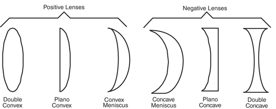
Figure 32-8 Lenses come in a variety of forms. Plano-convex and double-convex are among
the most common.
Lenses form two kinds of images: real and virtual. A real image is one that is focused to
a point in front of the lens, such as the image of the sun focused to a small disc on a piece
of paper. A virtual image is one that doesn’t come to a discrete focus. You see a virtual
image behind the lens, as when you are using a lens as a magnifying glass. Positive lenses,
which magnify the size of an object, create both real and virtual images. Their focal length
is stated as a positive number, such as +1 or +2.5. Negative lenses, which reduce the size
of an object, create only virtual images. Their focal length is stated as a negative number.
Lenses are common finds in surplus stores, and you may not have precise control over
what you get. For robotics vision applications, plano-convex or double-convex lenses of
about 0.5 to 1.25 in diameter are ideal. The focal length should be fairly short, about 1 to
3 in. When you are buying an assortment of lenses, the diameter and focal length of each
lens is usually provided, but if not, use a tape to measure the diameter of the lens and its
focal length (see Fig. 32-9). Use any point source except the sun—focusing the light of the
sun onto a small point can cause a fire!
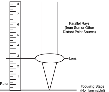
Figure 32-9 Use a bright light source, such as an
incandescent lamp, and a tape to measure the focal point of
a lens.
To use the lens, position it over the light cell(s) using any convenient mounting technique.
One approach is to glue the lens to a plastic or wood lens board. Or, if the lens is the correct
diameter, you can mount it inside a short length of plastic PVC pipe; attach the other
end of the pipe to the light cells. Be sure you block out stray light. You can use black construction
paper to create light baffles. This will make the robot see only the light shining
through the lens. If desired, attach a filter over the light cells. You can use a dab of glue to
secure the filter in place.
Using Fig. 32-6 as a guide, you can create a kind of two-eyed robot by placing a lens
over each group of four photocells. The lenses are mounted in front of the photocells, which are secured to a circuit board in two groups of four. The smaller the photocell is, the
easier it will be to mount with the lens (although soldering them may be more difficult). Each
of the eight cells is connected to a separate input of an eight-input analog-to-digital converter
(ADC) chip. By using an eight-input ADC, the values of all eight cells can be readily
sensed without the need for separate ADC chips and extra wiring.
Filters accept light at certain wavelengths and block all others. A common filter used in
robot design is intended to pass infrared radiation and block visible light. Such filters are
commonly used in front of phototransistors and photodiodes to block out unwanted ambient
(room) light. Only infrared light—from a laser diode, for instance—is allowed to pass
through and strike the sensor. Optical filters come in three general forms: colored gel, interference,
and dichroic.
- Colored gel filters are made by mixing dyes into a Mylar or plastic base. Good gel filters use dyes that are precisely controlled during manufacture to make filters that pass only certain colors. Depending on the dye used, the filter is capable of passing only a certain band of wavelengths. A good gel filter may have a bandpass region (the spectrum of light passed) of 40 to 60 nanometers (nm), which equates to nearly one full color of the basic six-color rainbow.
- Interference filters consist of several dielectric and sometimes metallic layers that each block a certain range of wavelengths. One layer may block light under 500 nm, and another layer may block light above 550 nm. The band between 500 and 550 nm is passed by the filter. Interference filters can be made to pass only a very small range of wavelengths.
- Dichroic filters use organic dyes or chemicals to absorb light at certain wavelengths. Some filters are made from crystals that exhibit two or more different colors when viewed at different axes. Color control is maintained by cutting the crystal at a specific axis.
Single- and multicell-vision systems are useful for detecting the absence or presence of light,
but they cannot make out the shapes of objects. This greatly limits the environment into
which such a robot can be placed. By detecting the shape of an object, a robot might be
able to make intelligent assumptions about its surroundings and perhaps be able to navigate
those surroundings, recognize its “master,” and more.
A few years ago, video vision was an expensive proposition for any robot experimenter.
But the advent of inexpensive and small pinhole and lipstick video cameras that can output
video data in a variety of different formats makes the hardware for machine vision affordable
(while still not a trivial exercise).
A video system for robot vision need not be overly sophisticated. The resolution of the
image can be as low as about 100 by 100 pixels (10,000 pixels total), though a resolution of no less than 300 by 200 pixels (60,000 pixels total) is preferred. The higher the resolution
is, the better the image and therefore the greater the robot’s ability to discern shapes.
A color camera is not mandatory and, in some cases, makes it harder to write suitable video
interpolating software.
Video systems that provide a digital output are generally easier to work with than those
that provide only an analog video output. You can connect digital video systems directly to
a PC, such as through a serial, parallel, or USB port. Analog video systems require that a
video capture card, a fast analog-to-digital converter, or some other similar device be
attached to the robot’s computer.
While the hardware for video vision is now affordable to most any robot builder, the job
of translating a visual image a robot can use requires high-speed processing and complicated
computer programming. Giving robots the ability to recognize shapes has proved to
be a difficult task. Consider the static image of a doorway. Our brains easily comprehend
the image, adapting to the angle at which we are viewing the doorway; the amount, direction,
and contrast of the light falling on it; the size and kind of frame used in the doorway;
whether the door is open or closed; and hundreds or even thousands of other variations.
Robot vision requires that each of these variables be analyzed, a job that requires computer
power and programming complexity beyond the means of most robot experimenters.
If a live full-motion video system seems too much for you, a small digital camera (like the
one shown in Fig. 32-10) can be added to a robot very easily. This camera was bought for under $20 at a local Radio Shack and can store 32 pictures at its highest resolution
(640 by 480 pixels, or VGA resolution), and the pictures can be downloaded to a PC
using a USB port. Depending on the camera and robot, you may have to modify the camera
to take pictures under computer control, but this should not be a significant amount
of work.
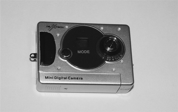
Figure 32-10 A small, inexpensive digital camera can be mounted to and controlled by your
robot very easily.
The camera mount on the robot can be a bit tricky. You will have to make sure that the
camera lens has an unobstructed view before it, the battery compartment must be accessible
as well as the USB interface. You will also have to provide access to the controls and
shutter release on the camera. The camera’s buttons can either be electronically controlled
(the interface follows) or physically pressed using a radio control servo controlled by the
robot. In either case, the camera mounting will have to be designed around all these interfaces
and apertures.
The prototype camera shown in Fig. 32-10 had a control button to place the camera in
a specific mode (depending on the number of times it was pressed). This button did not
seem to work reliably enough for an electronic control or a servo actuator—it seemed to
take a different number of presses to get the camera into a specific mode (as indicated by
an LCD display on the front of the camera). The decision was made to set the camera to a
specific mode before sending the robot out on a photographic “mission.” Along with this
simplification of the control interface, the decision was made to mount the camera to the
front of a robot using two-sided tape. There did not seem to be an easy solution to “hard”
mounting the camera and allowing access to the various controls and parts of the camera
except by mounting the camera by its back to the robot.
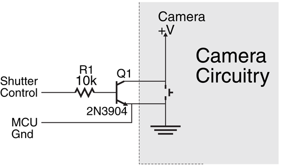
The camera’s shutter release was controlled electronically using the circuit shown in Fig. 32-11 (parts list in Table 32-3). To access the switch connections, a rotary tool was used to
cut away the plastic case on the back side, and the transistor’s collector and emitter were
soldered across the switch’s terminals. To find the negative connection of the switch to wire the transistor’s collector to, use a DMM to find the button lead that is connected directly to
the negative battery connection.
Q1 |
2N3904 NPN transistor |
R1 |
10k resistor |
Misc. |
Wiring, soldering iron, solder |
When a high voltage is applied to the Shutter Control line, the NPN transistor will turn
on and pull the high side of the switch to ground. The PBASIC instruction to take a picture
was the simple statement:
PULSOUT Pin, 100 which holds down the shutter release for 100 ms or 0.1 s, which was adequate for the camera
that was used.
If you do not feel comfortable opening up the camera body and probing to identify the
negative button lead, you can use a servo with a long arm on it to press the camera’s shutter release button. A servo could also be used for any operating mode controls, although as
previously noted, the camera that was used for the prototype did not seem to have a control
button that worked reliably enough for a servo (or electronic control) to engage it a set
number of times and to put the camera into the desired operating mode.
What makes adding a camera to the robot very interesting is the “mouse eye view” pictures
that you will get from your robot. Chances are you will think you know what the robot
will see before it, but in actuality, you will get a number of pictures that you will be hard
pressed to identify what are in them, like Fig. 32-12). Admittedly, the digital photograph’s
quality has been impaired by the low resolution (maximum 640 by 480 pixel) of the camera
used in the prototype, but the low perspective makes it very difficult to get a good understanding
of what the picture is of actually.
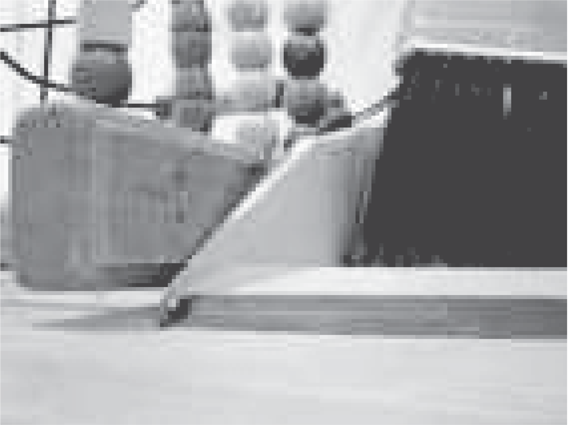
Figure 32-12 Photograph taken from a robot with the camera shown in Fig. 32-10 mounted on its front. The perspective could be described as a mouse's point of view.
In case you are wondering what Fig. 32-12) is a picture of, consider the more traditional
picture in Fig. 32-13). The camera took a picture of the edge of a broom and dustpan and
a child’s bead toy. This will probably be obvious after looking at Fig. 32-13), but when you
are just looking at the raw picture, you will be hard pressed to exactly identify what it is you
are seeing. The difficulty you had will give you an appreciation as well as some examples of
the scenes that a live video system will have to decode before the robot can move.
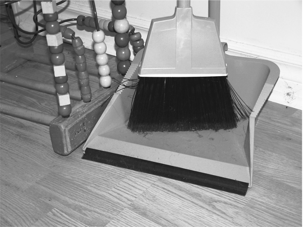
Figure 32-13 Human perspective on the photograph in Fig. 32-12. The scene is much clearer
and more obvious.
Here's another low-cost method of experimenting with robot vision that you might want
to tackle, and it uses only about $30 worth of parts (minus the video camera). You need a
simple penlight laser, a red filter, and a small piece of diffraction grating (available from
Edmund Scientific Company and other sources for optical components; see Appendix B,
"Sources," for additional information).
The system works on a principle similar to the three-beam focusing scheme used in CD
players. In a CD player, laser light is broken into sub-beams by the use of a diffraction grating.
A single, strong beam appears in the center, flanked by weaker beams on both sides,
as shown in Fig. 32-14). The three-beam CD focusing system uses the two closest side
beams, ignoring all the others.
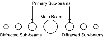
Figure 32-14 Most CD players use a diffraction grating
to break up the single laser beam into several sub-beams.
The sub-beams are used to focus and track the
optical system.
The beam spacing increases as the distance from the lens to the surface of the disc
increases. Similarly, the beam spacing decreases as the lens-to-CD distance decreases. A
multicelled photodetector in the CD players integrates the light reflected by these beams
and determines whether the lens should be moved closer to, or farther away from, the disc.
For history buffs, the fundamental basis of this focusing technique is over a hundred years
old and was pioneered by French physicist Jean Foucault.
CD players use a diffraction grating in which lines are scribed into a piece of plastic in
only one plane. This causes the laser beam to break up into several beams along the same
plane. With a diffraction grating that has lines scribed both vertically and horizontally, the
laser beam is split up into multiple beams that form a grid when projected on a flat surface
(see Figs. Fig. 32-15 and Fig. 32-16). The beams move closer together as the distance from the laser
and surface is decreased; the beams move farther apart as the distance from the laser and
surface is increased.
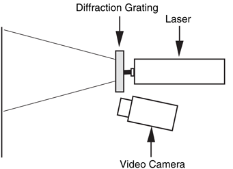
Figure 32-15 A penlight laser, diffraction grating,
filter, and video camera can be used to create a low-cost
machine vision system.
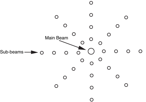
Figure 32-16 When projected onto a flat surface, the beams from the diffracted laser light
form a regular grid.
As you can guess, when the beams are projected onto a three-dimensional scene, they
form a kind of topographical map in which they appear closer or farther apart depending
on the distance of the object from the laser.
The red filter placed in front of the camera lens filters out most of the light except for the
red beams from the penlight laser. For best results, use a high-quality optical bandpass filter
that accepts only the precise wavelength of the diode laser, typically 635 or 680 nm. Check
the specifications of the laser you are using so you can get the correct filter. Meredith Instruments and Midwest Laser Products, among other sources, provide a variety of penlight
lasers and optical filters you can use (see Appendix B).
The main benefit of the laser diffraction system is this: it’s easier to write software that
measures the distance between pixels than it is to write software that attempts to recognize
shapes and patterns. For many machine vision applications, it is not as important for the
robot to recognize the actual shape of an object as it is to navigate around or manipulate
that shape. As an example, a robot may see a chair in its path, but there is little practical
need for it to recognize the chair as an early-eighteenth-century Queen Anne–style two-seater settee. All it really needs to know is that something is there, and by moving left or
right that object can be avoided.
Sight provides a fast and efficient way for us to determine our surroundings. The eyes take
in a wide field, and the brain processes what the eyes see to compose a picture of the
immediate environment. Taking a cue from the special senses evolved by some animals,
however, visual eyesight is not the only way to see. For instance, bats use high-pitched
sound to quickly and efficiently navigate through dark caves. So accurate is their sonar that
bats can sense tiny insects flying a dozen or more feet away.
Similarly, robots don’t always need light-sensitive vision systems. You may want to consider
using an alternative system, either instead of or in addition to light-sensitive vision.
The following sections outline some affordable technologies you can easily use.
Like a bat, your robot can use high-frequency sounds to navigate its surroundings. Ultrasonic
transducers are common in Polaroid instant cameras, electronic tape-measuring
devices, automotive backup alarms, and security systems. All work by sending out a high-frequency
burst of sound, then measuring the amount of time it takes to receive the
reflected sound.
Ultrasonic systems are designed to determine distance between the transducer and an
object in front of it. More accurate versions can map an area to create a type of topographical
image, showing the relative distances of several nearby objects along a kind of
3-D plane. Such ultrasonic systems are regularly used in the medical field (e.g., an ultrasound
picture of a baby still inside the mother). Some transducers are designed to be used
in pairs: one transducer to emit a series of short ultrasonic bursts, another transducer to
receive the sound. Other transducers, such as the kind used on Polaroid cameras and electronic
tape-measuring devices, combine the transmitter and receiver into one unit. It should
be noted that ultrasonics tend to require a great deal of power making them best suited for
large robots.
An important aspect of ultrasonic imagery is that high sound frequencies disperse less
readily than do low-frequency ones. That is, the sound wave produced by a high-frequency
source spreads out much less broadly than the sound wave from a low-frequency source.
This phenomenon improves the accuracy of ultrasonic systems. Both DigiKey and All Electronics,
among others, have been known to carry new and surplus ultrasonic components
suitable for robot experimenters. See Chapter 30 for more information on using ultrasonic
sensors to guide your robots.
Radar systems work on the same basic principle as ultrasonics, but instead of high-frequency
sound they use a high-frequency radio wave. Most people know about the high-powered radar equipment used in aviation, but lower-powered versions are commonly used
in security systems, automatic door openers, automotive backup alarms, and of course,
speed-measuring devices used by the police.
Radar is less commonly found on robotics systems because it costs more than ultrasonics.
This may change in the future with the availability of low-cost and low-power ultra-wideband
(UWB) radar. Rather than emitting a radio signal at a single frequency, UWB
emits a signal at a wide range of frequencies (from 1 Hz to several GHz). This wide range
of frequencies makes UWB radar sensitive to virtually all objects, allowing you to sense
effectively all objects in front of the robot, without having to resort to multiple sensors to
ensure that nothing is missed. As indicated, UWB radar is not yet available for hobby robotics,
but this will change as it becomes available in more and more products and hackable
units become available.
A favorite for security systems and automatic outdoor lighting, passive pyroelectric infrared
(PIR) sensors detect the natural heat that all objects emit. This heat takes the form of
infrared radiation—a form of light that is beyond the limits of human vision. The PIR system
merely detects a rapid change in the heat reaching the sensor; such a change usually
represents movement.
The typical PIR sensor is equipped with either a Fresnel or motion detection lens. The
Fresnel lens focuses infrared light from a fairly wide area onto the pea-sized surface of the
detector. In a robotics vision application, you can replace the Fresnel lens with a telephoto
lens arrangement that permits the detector to view only a small area at a time. Mounted
onto a movable platform, the sensor could detect the instantaneous variations of infrared
radiation of whatever objects are in front of the robot. See Chapter 30, "Object Detection,"
for more information on the use of PIR sensors.
The motion detection lens is the faceted lens that you have probably seen on a burglar
alarm object sensor. The facets pass infrared light from different positions to the PIR sensor.
When there is a single infrared light source (e.g., an intruder), as they move across the
motion detector lens’ field of view, the facets that pass the infrared light to the PIR sensor
changes. This change results in a change in the amount of infrared light hitting the PIR sensor,
allowing it to detect the motion of a hot object in front of it. To compensate for changing
temperatures in a room, a new “reference” infrared light level is continually checked
against the previously stored value and if the difference is within an acceptable range, the
system accepts this as the new reference else it sounds the alarm.
Many robots can be effective navigators with little more than a switch or two to guide their
way. Each switch on the robot is a kind of touch sensor: when a switch is depressed, the
robot knows it has touched some object in front of it. Based on this information, the robot
can stop and negotiate a different path to its destination.
To be useful, the robot’s touch sensors must be mounted where they will come into contact
with the objects in their surroundings. For example, you can mount four switches
along the bottom periphery of a square-shaped robot so contact with any object will trigger one of the switches. Mechanical switches are triggered only on physical contact;
switches that use reflected infrared light or capacitance can be triggered by the proximity
of objects. Noncontact switches are useful if the robot might be damaged by running into
an object, or vice versa. See Chapter 35, “Adding the Sense of Touch,” for more information
on tactile sensors.
To learn more about . . . |
Read |
|
Using a computer within your robot |
Chapter 12, "An Overview of Robot 'Brains' " |
|
Connecting sensors to a robot computer or microcontroller |
Chapter 14,"Computer Peripherals" |
|
Using touch to guide your robot |
Chapter 29,"The Sense of Touch" |
|
Getting your robot from point A to point B |
Chapter 33, "Navigation" |