PRINCIPLES OF
ROBOT LOCOMOTION
ROBOT LOCOMOTION
As you graduate to building larger mobile robots, you should consider the physical
properties of your creations, including their size, weight, and mode of transport. A
robot that is too heavy for its frame, or a locomotion mechanism that doesn’t provide sufficient stability, will greatly hinder the usefulness of your mechanical invention.
In this chapter you’ll find a collection of assorted tips, suggestions, and caveats for
designing the locomotion systems for your robots. Because the locomotion system is intimately related to the frame of the robot, we’ll cover frames a little bit as well, including their weight and weight distribution. Of course, there’s more to the art and science of robot locomotion than we can possibly cover here, but what follows will serve as a good introduction.
Most hobbyist robots weigh under 20 lbs, and a high percentage of those weigh under 10
lbs. Weight is one of the most important factors affecting the mobility of a robot. A heavy
robot requires larger motors and higher capacity batteries—both of which add even more
pounds to the machine. At some point, the robot becomes too heavy to even move.
On the other hand, robots designed for heavy-duty work often need some girth and
weight. Your own design may call for a robot that needs to weigh a particular amount in order for it to do the work you have envisioned. The parts of a robot that contribute the
most to its weight are the following, in (typical) descending order:
- Batteries
- Drive motors
- Frame
A 12-V battery pack can weigh 1 lb; larger-capacity, sealed lead-acid batteries can weigh
5 to 8 lbs. Heavier-duty motors will be needed to move that battery ballast. But bigger and
stronger motors weigh more because they must be made of metal and use heavier-duty
bushings. And they cost more. Suddenly, your “little robot” is not so little anymore; it has
become overweight and expensive.
If you find that your robot is becoming too heavy, consider putting it on a diet, starting with
the batteries. Nickel-cadmium and nickel metal hydride batteries weigh less, volt for volt,
than their lead-acid counterparts. While nickel-cadmium and nickel metal hydride batteries
may not deliver the amp-hour capacity that a large, sealed lead-acid battery will, your robot
will weigh less and therefore may not require the same stringent battery ratings as you had
originally thought.
When looking at reducing the weight of your robot or modifying it in any way, remember
to try to come up with changes that result in additional benefits. For example, if you
were to change your batteries to a lighter set, you will discover that you do not need as powerful
a motor. Less powerful motors weigh less than the originally specified motors, further
decreasing the weight of the motor. This decrease in the weight of the motor could result in
the need for smaller and lighter batteries, which allows you to look at using even smaller and
lighter batteries, smaller motors, smaller structure, etcetera. This process can repeat multiple
times and it isn’t unusual to see a situation where a 10 percent decrease in battery
weight results in a 50 percent reduction in overall robot weight. The repeating positive
response to a single change is known as a supereffect, and you should remember that the
reverse is also true: a 10 percent increase in weight in a robot’s components could result in
a 50 percent increase in weight in the final robot.
If your robot must use a lead-acid battery, consider carefully whether you truly need the
capacity of the battery or batteries you have chosen. You may be able to install a smaller
battery with a lower amp-hour rating. The battery will weigh less, but, understandably, it will
need to be recharged more often. An in-use time of 60 to 120 minutes is reasonable (that
is, the robot’s batteries must be recharged after an hour or two of continual use).
If you require longer operational times but still need to keep the weight down, consider
a replaceable battery system. Mount the battery where it can be easily removed. When the
charge on the battery goes down, take it out and replace it with a fully charged one. Place
the previously used battery in the charger. The good news is that smaller, lower capacity batteries
tend to be significantly less expensive than their larger cousins, so you can probably
buy two or three smaller batteries for the price of a single big one.
Drive motors are most often selected because of their availability and cost, not because
of their weight or construction. In fact, many robots are designed around the specifications
of the selected drive motors. The motors are selected (often they’re purchased surplus), and
from these the frame of the robot is designed and appropriate batteries are added. Still, it’s
important to give more thought to the selection of the motors for the robot that you have
in mind. Avoid motors that are obviously overpowered in relation to the robot in which they
are being used. Motors that are grossly oversized will add unnecessary weight, and they will
require larger (and therefore heavier and more expensive) batteries to operate.
The frame of the robot can add a surprising amount of weight. An 18-in2, 2-ft high robot
constructed from extruded aluminum and plastic panels might weigh in excess of 20 or 30
lbs, without motors and batteries. The same robot in wood (of sufficient strength and quality)
could weigh even more.
Consider ways to lighten your heavy robots, but without sacrificing strength. This can be
done by selecting a different construction material and/or by using different construction
techniques. For example, instead of building the base of your robot using solid  -in (or
thicker) aluminum sheet, consider an aluminum frame with crossbar members for added stability.
If you need a surface on which to mount components (the batteries and motors will
be mounted to the aluminum frame pieces), add a
-in (or
thicker) aluminum sheet, consider an aluminum frame with crossbar members for added stability.
If you need a surface on which to mount components (the batteries and motors will
be mounted to the aluminum frame pieces), add a  -in acrylic plastic sheet as a "skin" over
the frame. The plastic is strong enough to mount circuit boards, sensors, and other lightweight
components on it.
-in acrylic plastic sheet as a "skin" over
the frame. The plastic is strong enough to mount circuit boards, sensors, and other lightweight
components on it.
-in (or
thicker) aluminum sheet, consider an aluminum frame with crossbar members for added stability.
If you need a surface on which to mount components (the batteries and motors will
be mounted to the aluminum frame pieces), add a -in acrylic plastic sheet as a "skin" over
the frame. The plastic is strong enough to mount circuit boards, sensors, and other lightweight
components on it.Aluminum and acrylic plastic aren’t your only choices for frame materials. Other metals
are available as well, but they have a higher weight-to-size ratio. Both steel and brass weigh
several times more per square inch than aluminum. Brass sheets, rods, and tubes (both
round and square) are commonly available at hobby stores. Unless your robot requires the
added strength that brass provides, you may wish to avoid it because of its heavier weight.
Ordinary acrylic plastic is rather dense and therefore fairly heavy, considering its size.
Lighter-weight plastics are available but not always easy to find. For example, ABS and
PVC plastic—popular for plumbing pipes—can be purchased from larger plastics distributors
in rod, tube, and sheet form. There are many special-purpose plastics available that
boast both structural strength and light weight. Look for Sintra plastic, for example, which
has an expanded core and smooth sides and is therefore lighter than most other plastics.
Check the availability of glues and cements before you purchase or order any material. (See Chapter 10 for more on these and other plastics.)
For robots that have additional “decks,” like the robot shown in Fig. 18-1, select construction materials that will provide rigidity but the lowest possible weight. One technique, shown in the figure, is to use  -in thin-wall (Schedule 125) PVC pipe for uprights and attach the "decks" using
  or
or  all-thread rod. The PVC pipe encloses the all-thread; both act as a
strong support column. You need three such columns for a circular robot, and four columns
for a square robot. For small robots, consider electronic circuit board standoffs, which are
six-sided rods with the ends drilled and tapped for 4-40 screws.
all-thread rod. The PVC pipe encloses the all-thread; both act as a
strong support column. You need three such columns for a circular robot, and four columns
for a square robot. For small robots, consider electronic circuit board standoffs, which are
six-sided rods with the ends drilled and tapped for 4-40 screws.
-in thin-wall (Schedule 125) PVC pipe for uprights and attach the "decks" using or all-thread rod. The PVC pipe encloses the all-thread; both act as a
strong support column. You need three such columns for a circular robot, and four columns
for a square robot. For small robots, consider electronic circuit board standoffs, which are
six-sided rods with the ends drilled and tapped for 4-40 screws.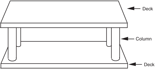
Figure 18-1 “Decked” robots provide extra space for batteries and electronics, but they can also add considerably to the weight. Use lightweight construction materials to avoid unduly increasing the weight of the robot.
Unless your robot is heavy, be sure to use the thinner-walled Schedule 125 PVC pipe.
Schedule 80 pipe, commonly used for irrigation systems, has a heavier wall and may not be
needed. Note that PVC pipe is always the same diameter outside, no matter how thick its
plastic walls. The thicker the wall, the smaller the inside diameter of the pipe. You can readily
cut PVC pipe to length using a PVC pipe cutter or a hacksaw, and you can paint it if you
don’t like the white color. Use Testor model paints for best results, and be sure to spray
lightly. For a bright white look, you can remove the blue marking ink on the outside of the
PVC pipe with acetone, which is available in the paint department of your local home
improvement store.
A critical issue in robot frame design is excessive weight that causes the frame to sag in the
middle. In a typical robot, a special problem arises when the frame sags: the wheels on
either side pivot on the frame and are no longer perpendicular to the ground. Instead, they
bow out at the bottom and in at the top (this is called negative camber). Depending on
which robot tires you use, traction errors can occur because the contact area of the wheel
is no longer consistent. As even more weight is added, the robot may have a tendency to
veer off to one side or the other.
There are three general fixes for this problem: reduce the weight, strengthen the frame,
or add cross-braces to prevent the wheels from cambering. Strengthening the frame usually
involves adding even more weight. So if you can, strive for the first solution instead—reduce
the weight.
If you can’t reduce weight, look for ways to add support beams or braces to prevent sagging.
An extra cross-brace along the wheelbase (perhaps stretched between the two motors)
may be all that’s required to prevent the problem. The cross-brace can be made of lightweight
aluminum tubing or even from a wooden dowel. The tubing or dowel does not need
to support any weight; it simply needs to act as a brace to prevent compression when the
frame sags and the wheels camber.
Yet another method is to apply extreme camber to the wheels, as shown in Fig. 18-2.
This minimizes the negative effects of any sagging, and if the tires have a high frictional surface
traction is not diminished. However, don’t do this with smooth, hard plastic wheels as
they don’t provide sufficient traction. You can camber the wheels outward or inward.
Inward (negative) camber was used in the old Topo and Bob robots made by Nolan Bushnell’s
failed Androbot company of the mid-1980s. The heavy-duty robot in Fig. 18-2 uses
outward (positive) camber. The robot can easily support over 20 lbs in addition to its own
weight, which is about 10 lbs, with battery, which is slung under the frame using industrial-strength
hook-and-loop (Velcro or similar) fasteners.

Figure 18-2 This “Tee-Bot” (so named because it employs the T-braces used for home construction)
uses extreme camber to avoid the frame sagging that results from too much weight.
Your robot’s horizontal center of balance (think of it as a balance scale) indicates how well
the weight of the robot is distributed on its base. If all the weight of a robot is to one side,
for example, then the base will have a lopsided horizontal center of balance. The result is
an unstable robot: the robot may not travel in a straight line and it might even tip over.
Ideally, the horizontal center of balance of a robot should be the center of its base (see
Fig. 18-3a). Some variation of this theme is allowable, depending on the construction of the
robot. For a robot with a single balancing caster, as shown in Fig. 18-3b, it is usually acceptable
to place more weight over the drive wheels and less on the caster. This increases traction,
and as long as the horizontal center of balance isn’t extreme there is no risk that the
robot will tip over.
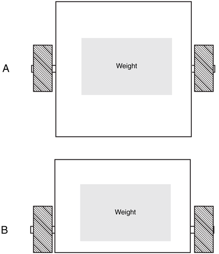
Figure 18-3 The distribution of weight on a robot affects its stability
and traction. a. Centering the weight down the middle in a robot
with two balancing casters; b. sliding the center of balance toward the
drive wheel in a single-caster ’bot.
Unequal weight distribution is the most troublesome result if the horizontal center of balance favors one wheel or track over the other—the right side versus the left side, for example. This can cause the robot to continually “crab” toward the heavier side. Since the heavier
side has more weight, traction is improved, but motor speed may be impaired because of the extra load.
City skyscrapers must be rooted firmly in the ground or else there is a risk they will topple
over in the slightest wind. The taller an object is, the higher its center of gravity. Of critical
importance to vertical center of gravity is the “footprint” or base area of the object—that is,
the amount of area in contact with the ground. The ratio between the vertical center of
gravity and the area of the base determines how likely it is that the object will fall over. A
robot with a small base but high vertical center of gravity risks toppling over. You can correct
such a design in either of two ways:
- Reduce the height of the robot to better match the area of the base, or
- Increase the area of the base to compensate for the height of the robot.
(There is also a third method called dynamic balance. Here, mechanical weight is
dynamically repositioned to keep the robot on even kilter. These systems are difficult to
engineer and, in any event, are beyond the scope of this book.)
Which method you choose will largely depend on what you plan to use your robot for.
For example, a robot that must interact with people should be at least toddler height. For a
pet-size robot, you’ll probably not want to reduce the height, but rather increase the base
area to prevent the robot from tipping over.
The way your robot gets from point A to point B is called locomotion. Robot locomotion
takes many forms, but wheels and tracks are the most common. Legged robots are also
popular, especially among hobbyists, as designing them represents a challenge both in construction
and weight-balance dynamics.
Wheels, and to a lesser extent tracks, are the most common means chosen to move robots
around. However, some wheels are better for mobile robots than others. Some of the
design considerations you may want to keep in mind include the following:
- The wider the wheels, the more the robot will tend to stay on course. With very narrow wheels, the robot may have a tendency to favor one side or the other and will trace a slow curve instead of a straight line. Conversely, if the wheels are too wide, the friction created by the excess wheel area contacting the ground may hinder the robot’s ability to make smooth turns.
- Two driven wheels positioned on either side of the robot (and balanced by one or two casters on either end) can provide full mobility. This is the most common drive wheel arrangement and is called a differential drive.
- Tracks turn by skidding or slipping, and they are best used on surfaces such as dirt that readily allow low-friction steering.
- Four or more driven wheels, mounted in sets on each side, will function much like tracks. In tight turns, the wheels will experience significant skidding, and they will therefore create friction over any running surface. If you choose this design, position the wheel sets close together.
- You should select wheel and track material to reflect the surface the robot will be used on. Rubber and foam are common choices; both provide adequate grip for most kinds of surfaces. Foam tires are lighter in weight, but they don’t skid well on hard surfaces (such as hardwood or tile floors).
Thanks to the ready availability of smart microcontrollers, along with the low cost of R/C
(radio-controlled) servos, legged automatons are becoming a popular alternative for robot
builders. Robots with legs require more precise construction than the average wheeled
robot. They also tend to be more expensive. Even a basic six-legged walking robot requires
a minimum of two or three servos, with some six- and eight-leg designs requiring 12 or
more motors. At about $12 per servo (more for higher-quality ones), the cost can add up
quickly!
Obviously, the first design decision is the number of legs. Robots with one leg (hoppers)
or two legs are the most difficult to build because of balance issues, and will not be
addressed here. Robots with four and six legs are more common. Six legs offer a static balance
that ensures the robot won’t easily fall over. At any one time, a minimum of three legs
touch the ground, forming a stable tripod.
In a four-legged robot, either the robot must move one leg at a time—keeping the other
three on the ground for stability—or else employ some kind of dynamic balance when only
two of its legs are on the ground at any given time. Dynamic balance is often accomplished
by repositioning the robot’s center of gravity, typically by moving a weight (such as the
robot’s head or tail, if it has one). This momentarily redistributes the center of balance to
prevent the robot from falling over. The algorithms and mechanisms for achieving dynamic
balance are not trivial. Four-legged robots are difficult to steer, unless you add additional
degrees of freedom for each leg or articulate the body of the beast like those weird segmented
city buses you occasionally see.
The movement of the legs with respect to the robot’s body is often neglected in the
design of legged robots. The typical six-legged (hexapod) robot uses six identical legs. Yet
the crawling insect a hexapod robot attempts to mimic is designed with legs of different
lengths and proportions—the legs are made to do different things. The back legs of an
insect, for example, are often longer and are positioned near the back for pushing (this is
particularly true of insects that burrow through dirt). The front legs may be similarly constructed for digging, carrying food, fighting, and walking. You may wish to replicate this
design, or something similar, for your own robots. Watch some documentaries on insects
and study how they walk and how their legs are articulated. Remember that the cockroach
has been around for over a million years and represents a very advanced form of biological
engineering!
Next to the batteries, the drive motors are probably the heaviest component in your robot.
You’ll want to carefully consider where the drive motor(s) are located and how the weight is
distributed throughout the base.
One of the most popular mobile robot designs uses two identical motors to spin two
wheels on opposite sides of the base (the differentially driven robot). These wheels provide
forward and backward locomotion, as shown in Fig. 18-4, as well as left and right steering.
If you stop the left motor, the robot turns to the left. By reversing the motors relative to one
another, the robot turns by spinning on its wheel axis (turns in place). You use this forward-reverse
movement to make hard or sharp right and left turns.
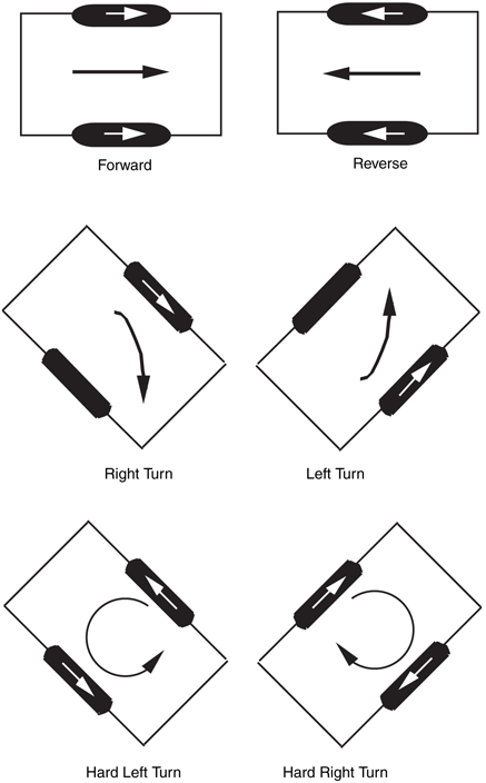
Figure 18-4 Two motors mounted on either side of the robot can
power two wheels. Casters provide balance. The robot steers by changing
the speed and direction of each motor.
You can place the wheels—and hence the motors—just about anywhere along the length
of the platform. If they are placed in the middle, as shown in Fig. 18-5, you should add
two casters to either end of the platform to provide stability. Since the motors are in the
center of the platform, the weight is more evenly distributed across it. You can place the
battery or batteries above the centerline of the wheel axis, which will maintain the even
distribution.
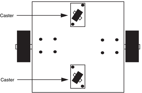
Figure 18-5 A robot with a centerline motor mount uses two casters
(very occasionally one) for balance. When using one caster, you may need
to shift the balance of weight toward the caster end to avoid having the
robot tip over.
A benefit of centerline mounting is that the robot has no “front” or “back,” at least as far
as the drive system is concerned. Therefore, you can create a kind of multidirectional robot
that can move forward and backward with the same ease. Of course, this approach also
complicates the sensor arrangement of your robot. Instead of having bump switches only in
the front of your robot, you’ll need to add additional ones in the back in case the robot is
reversing direction when it strikes an object.
You can also position the wheels on one end of the platform. In this case, you add one
caster on the other end to provide stability and a pivot for turning, as shown in Fig. 18-6.
Obviously, the weight is now concentrated more on the motor side of the platform. You
should place more weight over the drive wheels, but avoid putting all the weight there since
maneuverability and stability may be diminished.
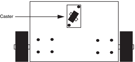
Figure 18-6 A robot with a front-drive motor mount uses a single
opposing caster for balance. Steering is accomplished using the same technique
as a centerline motor mount.
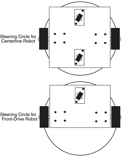
One advantage of front-drive mounting is that it simplifies the construction of the robot.
Its steering circle, the diameter of the circle in which the robot can be steered, is still the same diameter as the centerline drive robot. However, it extends beyond the front/back
dimension of the robot (see Fig. 18-7). This may or may not be a problem, depending on
the overall size of your robot and how you plan to use it. Any given front-drive robot may
be smaller than its centerline drive cousin. Because of the difference in their physical size,
the diameter of the steering circle for both may be about the same.
As mentioned earlier, most robots employing the two-motor drive system use at least one
unpowered caster, which provides support and balance. Two casters are common in robots
that use centerline drive-wheel mounting. Each caster is positioned at opposite ends of the
robot. When selecting casters it is important to consider the following factors:
- The size of the caster wheel should be in proportion to the drive wheels (see Fig. 18-8).
- When the robot is on the ground, the drive motors must firmly touch terra firma. If the caster wheels are too large, the drive motors may not make adequate contact, and poor traction will result. You might also consider using a suspension system of your own design on the casters to compensate for uneven terrain.
- The casters should spin and swivel freely. A caster that doesn’t spin freely will impede the robot’s movement.
- In most cases, since the caster is provided only for support and not traction you should construct the caster from a hard material to reduce friction. A caster made of soft rubber will introduce more friction, and it may affect a robot’s movements.
- Consider using ball casters (also called ball transfers), which are primarily designed to
be used in materials processing (conveyor chutes and the like). Ball casters (see Fig. 18-9)
are made of a single ball—either metal or rubber—held captive in a housing, and they
function as omnidirectional casters for your robot. The size of the ball varies from about
 to over 3 in in diameter. Look for ball casters at mechanical surplus stores and also
at industrial supply outlets, such as Grainger and McMaster–;Carr.
to over 3 in in diameter. Look for ball casters at mechanical surplus stores and also
at industrial supply outlets, such as Grainger and McMaster–;Carr.
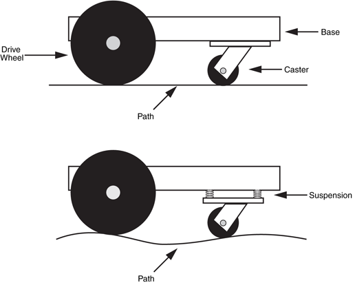
Figure 18-8 The height of the caster with respect to the drive wheels will greatly
influence the robot’s traction and maneuverability. A spring-loaded caster (a kind of
suspension) can improve functionality of the robot on semirough terrain.

Figure 18-9 Ball casters (or ball transfers) are omnidirectional. For medium- to
large-sized robots consider using them instead of wheeled casters.
A variety of methods are available to steer your robot. The following sections describe several of the more common approaches.
For wheeled and tracked robots, differential steering is the most common method for getting
the machine to go in a different direction. The technique is exactly the same as steering
a military tank: one side of wheels or treads stops or reverses direction while the other
side keeps going. The result is that the robot turns in the direction of the stopped or
reversed wheel or tread. Because of friction effects, differential steering is most practical
with two-wheel-drive systems. Additional sets of wheels, as well as rubber treads, can
increase friction during steering.
- If you are using multiple wheels (dually), position the wheels close together, as shown in Fig. 18-10. The robot will pivot at a virtual point midway between the two wheels on each side.
- If you are using treads, select a relatively low-friction material such as cloth or hard plastic. Very soft rubber treads will not steer well on smooth surfaces. If this cannot be helped, one approach is to always steer by reversing the tread directions. This will reduce the friction.
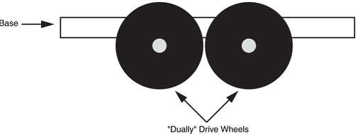
Figure 18-10 “Dually” wheels should be placed close to one another. If they
are spaced farther apart the robot cannot steer as easily.
Pivoting the wheels in the front is yet another method for steering a robot (see Fig. 18-11).
Robots with car-type steering are not as maneuverable as differentially steered robots, but
they are better suited for outdoor uses, especially over rough terrain. You can obtain somewhat
better traction and steering accuracy if the wheel on the inside of the turn pivots more
than the wheel on the outside. This technique is called Ackerman steering and is found on
most cars but not on as many robots.
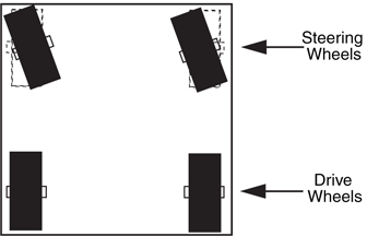
Figure 18-11 Car-type steering offers a workable alternative for an outdoors robot, but it is less useful indoors or in places where there are many obstructions that must be steered around.
One of the biggest drawbacks of the differentially steered robot is that the robot will veer off
course if one motor is even a wee bit slow. You can compensate for this by monitoring the
speed of both motors and ensuring that they operate at the same r/min. This typically
requires a control computer, as well as added electronics and mechanical parts for sensing
the speed of the wheels.
Car-type steering, described in the last section, is one method for avoiding the problem
of “crabbing” as a result of differences in motor speed simply because the robot is driven by
just one motor. But car-type steering makes for fairly cumbersome indoor mobile robots. A
better approach is to use a single drive motor powering two rear wheels and a single steering
wheel in the front. This arrangement is just like a child’s tricycle, as shown in Fig. 18-12.
The robot can be steered in a circle just slightly larger than the width of the machine. Be
careful about the wheelbase of the robot (distance from the back wheels to the front steering
wheel). A short base will cause instability in turns, and the robot will tip over opposite the
direction of the turn.
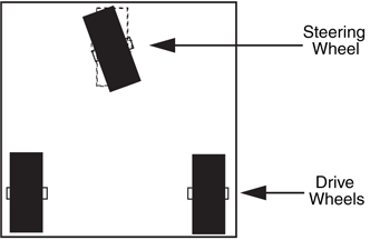
Figure 18-12 In tricycle steering, one drive motor powers the robot and a single wheel in front steers the robot. Try and to avoid short wheelbases as this can result in a robot that tips easily when the robot turns.
Tricycle-steered robots must have a very accurate steering motor in the front. The
motor must be able to position the front wheel with subdegree accuracy. Otherwise,
there is no guarantee the robot will be able to travel a straight line. Most often, the steering wheel is controlled by a servo motor. Servo motors use a closed-loop feedback system that provides a high degree of positional accuracy (depending on the quality of the
motor, of course). Read more about servo motors in Chapter 22, “Working with Servo
Motors.”
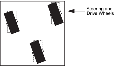
To have the highest tech of all robots, you may want omnidirectional drive. It uses steerable
drive wheels, usually at least three, as shown in Fig. 18-13. The wheels are operated by two
motors: one for locomotion and one for steering. In the usual arrangement, the drive/steering
wheels are ganged together using gears, rollers, chains, or pulleys. Omnidirectional
robots exhibit excellent maneuverability and steering accuracy, but they are technically
more difficult to construct.
The speed of the drive motors is one of two elements that determines the travel speed of
your robot. The other is the diameter of the wheels. For most applications, the speed of the
drive motors should be under 130 r/min (under load). With wheels of average size, the
resultant travel speed will be approximately 4 ft/s. That’s actually pretty fast. A better travel
speed is 1 to 2 f/s (approximately 65 r/min), which requires smaller diameter wheels, a
slower motor, or both.
How do you calculate the travel speed of your robot? Follow these steps:
1. Divide the r/min speed of the motor by 60. The result is the revolutions of the motor
per second (r/s). A 100-r/min motor runs at 1.66 r/s.
2. Multiply the diameter of the drive wheel by pi, or approximately 3.14. This yields the
circumference of the wheel. A 7-in wheel has a circumference of about 21.98 in.
3. Multiply the speed of the motor (in r/s) by the circumference of the wheel. The result is
the number of linear inches covered by the wheel in 1 s.
With a 100-r/min motor and 7-in wheel, the robot will travel at a top speed of 35.168
in/s, or just under 3 ft. That’s about 2 mi/h! You can readily see that you can slow down
a robot by decreasing the size of the wheel. By reducing the wheel to 5 in instead of 8, the
same 100-r/min motor will propel the robot at about 25 in/s. By reducing the motor
speed to, say, 75 r/min, the travel speed falls even more, to 19.625 in/s. Now that’s more
reasonable.
Bear in mind that the actual travel speed once the robot is all put together may be lower
than this. The heavier the robot, the larger the load on the motors, so the slower it will turn.
Robots can’t locomote where they can’t fit. Obviously, a robot that’s too large to fit through
doorways and halls will have a hard time of it. In addition, the overall shape of a robot will
also dictate how maneuverable it is, especially indoors. If you want to navigate your robot
in tight areas, you should consider its basic shape: round or square.
- A round robot is generally able to pass through smaller openings, no matter what its orientation when going through the opening (see Fig. 18-14). To make a round robot, you must either buy or make a rounded base or frame. Whether you’re working with metal, steel, or wood, a round base or frame is not as easy to construct as a square one.
- A square robot must orient itself so that it passes through openings straight ahead rather than at an angle. Square-shaped robot bases and frames are easier to construct than round ones.
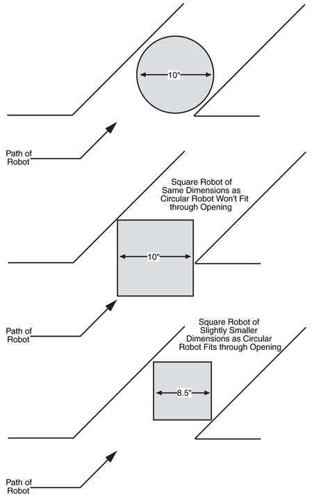
Figure 18-14 A round robot versus a square robot. All things
being equal, a round robot is better able to navigate through small
openings. However, rounded robots also have less usable surface area,
so a square-shaped robot can be made smaller and still support the
same on-board “real estate.”
While you’re deciding whether to build a round- or square-shaped robot, consider that
a circle of a given diameter has less surface area than a square of the same width. For
example, a 10-in circle has a surface area of about 78 in2. Moreover, because the surface
of the base is circular, less of it will be useful for your robot (unless your printed circuit
boards are also circular). Conversely, a 10-by-10-in square robot has a surface area
of 100 in. Such a robot could be reduced to about 8.5 in2, and it would have about the
same surface area as a 10-in round robot, and its surface area would be generally more
usable.
To learn more about . . . |
Read |
|
Selecting wood, plastic, or metal to construct your robot |
||
Choosing a battery for your robot |
Chapter 17, "Batteries and Robot Power Supplies" |
|
Selecting motors |
Chapter 18, "Choosing the Right Motor" |
|
Building a walking robot |
Chapter 24, "Build a Heavy-Duty Six-Legged Walking Robot" |
|
Constructing a treaded robot |
Chapter 25, "Advanced Locomotion Systems" |
|
Controlling the speed of a two-motor-driven robot |
Chapter 20, "Working with DC Motors" |