BATTERIES AND ROBOT
POWER SUPPLIES
POWER SUPPLIES
The robots in science fiction films are seldom like the robots in real life. Take the robot
power supply. In the movies, robots almost always have some type of advanced nuclear
drive or perhaps a space-age solar cell that can soak up the sun’s energy, then slowly
release it over two or three days. Nuclear power supplies are obviously out of the question.
And solar cells don’t provide enough power for the typical motorized robot, and as yet they
have no power storage capabilities.
Most self-contained real-life robots are powered by batteries, the same kind of batteries
used to provide juice to a flashlight, cassette radio, portable television, or other electrical
device. Batteries are an integral part of robot design, as important as the frame, motor, and
electronic brain—those components we most often think of when the discussion turns to
robots. To robots, batteries are lifeblood; without them robots cease to function.
While great strides have been made in electronics during the past 20 years—including
entire computers that fit on a chip—battery technology still has a way to go. Today’s
advanced batteries, used in laptops, cell phones, and remote control vehicles, are able to
store significantly more energy than batteries of even five years ago but still don’t hold
enough energy for their size, weight, and cost. For most robot applications, the most efficient
power source is common alkaline and nickel-metal hydride (NiMH) batteries that can
provide more than adequate power to all of your robot creations with judicious planning
and use.
Anytime you are working with electricity, remember to make sure that you understand
how much energy is available in the different power supplies and make sure that there is
adequate protection—even a AA alkaline radio battery, when shorted out, can produce
enough heat to melt the clips that it is in and char the battery’s plastic coating, potentially
causing a fire.
Be extra careful when wiring power supply circuits that convert household 120 V AC to
low DC voltages and triple-check your work. Never operate the supply when the top of the
cabinet is off, unless you are testing it. Even then, stay away from the incoming AC. Touching
the incoming AC voltage can cause a serious shock, and depending on the circumstances
it could kill you. Be extra certain that no wires touch the chassis or front panel. Use
an all-plastic enclosure whenever possible.
Do not operate any power supply if it has become wet, has been dropped, or shows signs
of visible damage. Fix any problems before powering it up. Understand the fuse requirements
for the power supply and robot and do not assemble the supply without a fuse.
It is not widely known or understood, but of the various parameters that are used to choose
a battery for an application (such as voltage output, amp-hour rating, recharge rate, etc.)
the most important one for robot applications is very rarely considered—the battery’s internal
resistance. Often people describing themselves as experts will tell you that you should
buy the cheapest carbon zinc batteries you can find instead of expensive alkaline or
rechargeable batteries because the ampere hour (AH) rating of the cheaper batteries is similar
to that of the much more expensive battery. This is true, but the inexpensive batteries
have a very high internal resistance, which will shorten their lives in your robot and make it
difficult for your robot to work reliably.
To understand the effect the internal resistance has in a robot, take a look at Fig. 17-1,
which shows three different robot battery power circuits. When you think of electrical circuits,
you tend to think of the idealized case (the left circuit diagram) in which there is no
resistance in wiring. This is a reasonable approximation when low power and current power
sources are being considered. In a robot application, which draws a great deal of current,
the internal resistances of the batteries (shown in the middle circuit diagram) have a voltage
drop across them which becomes larger as more current is drawn from the batteries. The
combined internal resistances can be consolidated into a single resistance as shown in the
circuit diagram to the right, the “effective circuit.”
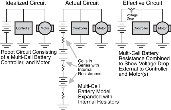
Figure 17-1 The effect of the internal resistance of a robot’s battery power source on the output
voltage available to the robot’s motors and electronics.
This voltage drop is actually a power loss to the robot. The batteries’ internal resistances
create heat, which is power lost in its most basic form. To make matters worse, most batteries
lose the ability to output electrical energy as their internal temperature rises, so this
internal resistance not only robs the robot of power, but also reduces the total amount of
power available from the batteries.
To summarize, the lower the internal resistance of the battery, the more power is available to the robot. While you may want to use cheap carbon zinc batteries for testing your
robot’s electronics, when it comes to moving you should use batteries with the lowest available
internal resistance as documented in the battery’s data sheet on the manufacturer’s
web page.
You can obtain higher voltages and current by connecting several cells together, as shown
in Fig. 17-2. There are two basic approaches:
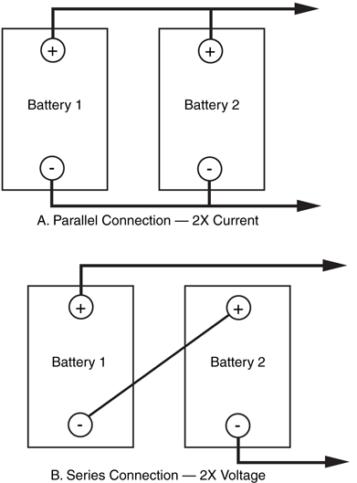
Figure 17-2 Wiring batteries
to increase ratings. a. Parallel
connection increases current;
b. Series connection increases
voltage.
- To increase voltage, connect the batteries in series. The resultant voltage is the sum of the voltage outputs of all the cells combined.
- To increase current, connect the batteries in parallel. The resultant current is the sum of the current capacities of all the cells combined.
Take note that when you connect cells together not all cells may be discharged or recharged
at the same rate. This is particularly true if you combine two half-used batteries with two
new ones. The new ones will do the lion’s share of the work and won’t last as long. Therefore,
you should always replace or recharge all the cells at once. Similarly, if one or more
of the cells in a battery pack are permanently damaged and can’t deliver or take on a charge
like the others, you should replace them.
There are seven main types of batteries, which come in a variety of shapes, sizes, and configurations.
Zinc batteries are the staple of the battery industry and are often referred to simply as flashlight
cells. The chemical makeup of zinc batteries takes two forms: carbon zinc and zinc
chloride. Carbon zinc, or regular-duty, batteries die out the quickest and are unsuited to
robotic applications. Zinc chloride, or heavy-duty, batteries provide a little more power than
regular carbon zinc cells and last 25 to 50 percent longer. Despite the added energy, zinc
chloride batteries are also unsuitable for most robotics applications.
Both carbon zinc and zinc chloride batteries can be rejuvenated a few times after being
drained. Zinc batteries are available in all the standard flashlight (D, C, A, AA, and AAA)
and lantern battery sizes.
Alkaline cells use a special alkaline manganese dioxide formula that lasts up to 800 percent
longer than carbon zinc batteries. The actual increase in life expectancy ranges from about
300 to 800 percent, depending on the application. In robotics, where the batteries are driving
motors, solenoids, and electronics, the average increase is a reasonable 500 percent or
five times the life of carbon zinc batteries.
Alkaline cells, which come in all the standard sizes (as well as 6- and 12-V lantern cells),
cost about twice as much as zinc batteries. But the increase in power and service life is
worth the cost. Unlike zinc batteries, however, ordinary alkaline batteries cannot be rejuvenated
by recharging without risking fire (though some people try it just the same). During
recharging, alkaline batteries generate considerable internal heat, which can cause them to
explode or catch fire. So when these batteries are dead, just throw them away.
Rechargeable alkaline cells have been on the market for a number of years now. These
provide many of the benefits of ordinary alkaline cells but with the added advantage of being
rechargeable. A special low-current recharger is required (don’t use the recharger on
another battery type or you may damage the recharger or the batteries). While rechargeable
alkalines cost more than ordinary alkaline cells, over time your savings from reusing the
batteries can be considerable.
You’ve probably seen the advertisements for the very high tech alkaline cells—ones that
offer two or three times the life of regular alkaline batteries. While being significantly more
expensive than regular alkaline batteries, they do indeed provide 200 to 300 percent of the
life of basic alkaline cells. The dramatic improvement in battery life is possible by decreasing
the internal resistance of the batteries and improving their ability to respond to changing
current demands (such as a motor turning on and off) without damaging the internal
structure of the battery.
The much higher price of the high-tech alkaline cells will often preclude their regular use
in a robot. They are good to keep in your back pocket for those times when you need a bit
more juice in a sumo-competition or the robot is having problems that more power (or less
weight) would solve.
Nickel metal hydride (NiMH) batteries are probably the optimal rechargeable battery technologies
for use in robots (and, practically speaking, all other applications that require batteries).
NiMH batteries can be recharged 400 or more times and have a low internal
resistance, so they can deliver high amounts of current. Nickel metal hydride batteries are
about the same size and weight as alkaline cells, but they deliver about 50 percent more
operating current than NiCads. In fact, NiMH batteries work best when they are used in
very high current situations. Unlike NiCads, NiMH batteries do not exhibit any memory
effect, nor do they contain cadmium, a highly toxic material.
NiMH cells are available in all standard sizes, plus special-purpose “sub” sizes for use in
sealed battery packs (as in rechargeable handheld vacuum cleaners, photoflash equipment, and so forth). Most sub-size batteries have solder tabs, so you can attach wires directly to the
battery instead of placing the cells in a battery holder. NiMH cells don’t last quite as long as
alkaline cells, but this deficiency is being addressed with the availability of high amp-hour
rated batteries at reasonable cost.
While NiMH batteries are discharging, especially at high currents, they can get quite hot.
You should consider this when you place the batteries in your robot. If the NiMH pack will
be pressed into high-current service, be sure it is located away from any components that
may be affected by the heat. This includes any control circuitry or the microcontroller.
NiMH batteries should be recharged using a recharger specially built for them—most
modern rechargers have a switch to specify whether the batteries are NiMH or NiCads.
According to NiMH battery makers, NiMH batteries should be charged at an aggressive
rate. A by-product of this kind of high-current recharging is that NiMH can be recycled back
into service more quickly than NiCads. You can deplete your NiMH battery pack, put it
under charge for an hour or two, and be back in business.
One disadvantage of NiMH relative to other rechargeable battery technologies is that the
battery does not hold the charge well. That is, over time (weeks, even days) the charge in
the battery is depleted, even while the battery is in storage. For this reason, it’s always a
good idea to put NiMH batteries on the recharger at regular intervals, even when they
haven’t been used. NiMH batteries do not exhibit the memory effect of NiCad batteries.
When you think “rechargeable battery,” you undoubtedly think nickel-cadmium (NiCad for
short). In recent years, NiCads have fallen out of favor due to the memory effect in which
the battery will tend to last only as long as it is usually asked to; if it is placed in longer service
periodically, it will not respond well. Another issue with NiCads is their chemical
makeup—cadmium is a highly toxic metal that should not be put into public landfill sites and
ideally should be disposed of as toxic waste.
If you decide to use NiCad batteries, remember that they can change output polarity—
positive becomes negative and vice versa—under certain circumstances. Polarity reversal is
common if the battery is left discharged for too long or if it is discharged below 75 or 80
percent capacity. Excessive discharging can occur if one or more cells in a battery pack
wears out. The adjacent cells must work overtime to compensate, and so they discharge
themselves too fast and too far.
You can test for polarity reversal by hooking the battery to a volt-ohm meter (remove it
from the pack if necessary). If you get a negative reading when the leads are connected
properly, the polarity of the cell is reversed. You can sometimes correct polarity reversal by
fully charging the battery (connecting it in the recharger in reverse), then shorting it out.
Repeat the process a couple of times if necessary. There is about a fifty-fifty chance that the
battery will survive this. The alternative is to throw the battery out, so you actually stand to
lose very little.
Lithium and rechargeable lithium-ion batteries are popular in laptop computers. They are
best used at a steady discharge rate and tend to be expensive. Lithium batteries of various types provide the highest energy density of most any other commercially available battery,
and they retain their charge for months, even years. Like other rechargeable battery types,
rechargeable lithium-ion batteries require their own special recharging circuitry, or overheating
and even fire could result.
The battery in your car is a lead-acid battery. It is made up of not much more than lead
plates crammed in a container that’s filled with an acid-based electrolyte. These brutes pack
a wallop and have an admirable between-charge life. When the battery goes dead, recharge
it, just like a NiCad.
Not all lead-acid batteries are as big as the one in your car. You can also get—new or
surplus—6-V lead-acid batteries that are about the size of a small radio. The battery is
sealed, so the acid doesn’t spill out (most automotive batteries are now sealed as well). The
sealing isn’t complete though: during charging, gases develop inside the battery and are
vented out through very small pores. Without proper venting, the battery would be ruined
after discharging and recharging. These batteries are often referred to as sealed lead-acid,
or SLA.
Lead-acid batteries typically come in self-contained packs. Six-volt packs are the most
common, but you can also get 12- and 24-V packs. The packs are actually made by combining
several smaller cells. The cells are wired together to provide the rated voltage of
the entire pack. Each cell typically provides 2.0 V, so three cells are required to make
a 6-V pack. You can, if you wish, take the pack apart, unsolder the cells, and use them
separately.
Although lead-acid batteries are powerful, they are heavy. A single 6-V pack can weigh
4 or 5 lb (2 to 2.5 kg). Lead-acid batteries are often used as a backup or emergency power supply for computers, lights, and telephone equipment. The cells are commonly available
on the surplus market, and although used they still have many more years of productive life.
The retail price of new lead-acid cells is about $25 for a 6-V pack. Surplus prices are 50 to
80 percent lower.
Motorcycle batteries make good power cells for robots. They are easy to get, compact,
and relatively lightweight. The batteries come in various amp-hour capacities, so you can
choose the best one for your application. New motorcycle batteries are somewhat pricey,
although you should be able to find surplus or used batteries for just a few dollars. You can
also use car batteries, as long as your robot is large and sturdy enough to support it.
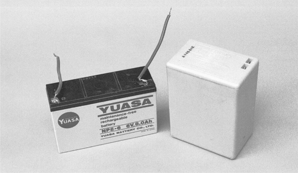
Gelled electrolyte batteries (commonly called gel-cell, after a popular trade name) use a
special gelled electrolyte and are the most common form of SLA batteries. They are
rechargeable and provide high current for a reasonable time, which makes them perfect for
robots. Fig. 17-3 shows typical sealed lead-acid batteries.
Batteries carry all sorts of ratings and specifications. Traditionally, the two most important
specifications are per-cell voltage and amp-hour current.
The voltage rating of a battery is fairly straightforward. If the cell is rated for 1.5 V, when
new, it puts out a bit more. Over time it will drop down to the rate value, give or take. That
“give or take” is more important than you may think because few batteries actually deliver
their rated voltage throughout their life span. Most rechargeable batteries are recharged 20
to 30 percent higher than their specified rating. For example, the 12-V battery in your car,
a type of lead-acid battery, is charged to about 13.8 V.
Standard zinc and alkaline flashlight batteries are rated at 1.5 V per cell. Assuming you
have a well-made battery in the first place, the voltage may actually be 1.65 V when the cell
is fresh, and drop to 1.3 V or less, at which point the battery is considered dead. The circuit
or motor you are powering with the battery must be able to operate sufficiently
throughout this range.
Most batteries are considered dead when their power level reaches 80 percent of their
rated voltage. That is, if the cell is rated at 6 V, it’s considered dead when it puts out only
4.8 V. Some equipment may still function at levels below 80 percent, but the efficiency of
the battery is greatly diminished. Below the 80 percent mark, the battery no longer provides
the rated current (discussed later), and if it is the rechargeable type, the cell is likely to be
damaged and unable to take a new charge. When experimenting with your robot systems,
keep a volt-ohm meter handy and periodically test the output of the batteries. Perform the
test while the battery is in use. The test results may be erroneous if you do not test the battery
under load.
It is often helpful to know the battery’s condition when the robot is in use. Using a DMM
to periodically test the robot’s power plant is inconvenient. But you can build a number of battery monitors into your robot that will sense voltage level. The output of the monitor can
be a light-emitting diode (LED), which will allow you to see the relative voltage level, or you
can connect the output to a circuit that instructs the robot to seek a recharge or turn off.
Several monitor circuits are discussed later in this chapter.
If your robot has an on-board computer, you want to avoid running out of juice midway
through some task. Not only will you lose the operating program and have to rekey or
reload it, but the robot may damage itself or its surroundings if the power to the computer
is suddenly turned off.
The capacity of a battery is rated as amp-hour current. This is the amount of power, in
amps or milliamps, the battery can deliver over a specified period of time. The amp-hour
current rating is a little like the current rating of an AC power line, but with a twist. AC
power is considered never ending, available night and day, always in the same quantity. But
a battery can only store so much energy before it poops out, so the useful service life must
be taken into account. The current rating of a battery is at least as important as the voltage
rating because a battery that can’t provide enough juice won’t be able to turn a motor or
sufficiently power all the electronic junk you’ve stuck onto your robot.
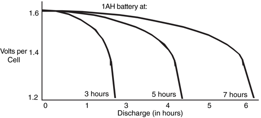
What exactly does the term amp-hour mean? Basically, the battery will be able to provide
the rated current for 1 h before failing. If a battery has a rating of 5 amp-hours
(expressed as AH), it can provide up to 5A continuously for 1 h, 1A for 5 h, and so forth,
as shown in Fig. 17-4. So far, so good, but the amp-hour rating is not that simple. The
5 AH rating is actually taken at a 10- or 20-h discharge interval. That is, the battery is used
for 10 or 20 h, at a low or medium discharge rate. After the specified time, the battery is
tested to see how much charge it has left. The rating of the battery is then calculated taking
the difference between the discharge rate and the reserve power and multiplying it by the
number of hours under test.

What this means is that it’s an unusual battery that provides the stated amps in the 1-h period. The battery is much more likely to fail after 30 or 45 min of heavy-duty use and
won’t be able to supply the specified current for more than about 15 to 20 min. Discharging
at or above the amp-hour rating may actually cause damage to the battery. This is especially
true of NiCad cells.
The lesson to be learned is that you should always choose a battery that has an amp-hour
rating 20 to 40 percent more than what you need to power your robot. Figuring the
desired capacity is nearly impossible until the entire robot is designed and built (unless you
are very good at computing current consumption). The best advice is to design the robot
with the largest battery you think practical. If you find that the battery is way too large for
the application, you can always swap it for a smaller one. It’s not so easy to do the
reverse.
Note that some components in your robot may draw excessive current when first
switched on, then settle down to a more reasonable level. Motors are a good example of
this. A motor that draws 1 A under load may actually require several amps at startup. The
period is very brief, on the order of 100 to 200 ms. No matter; the battery should be able
to accommodate the surge. This means that the 20 to 40 percent overhead in using the
larger battery is a necessity, not just a design suggestion. A rough comparison of the discharge
curve at various discharge times is shown in Fig. 17-5.
When the first editions of this book were written, most rechargeable batteries required a
slow charge process, often taking 12 to 24 h. Modern batteries and charges can perform
the task in significantly less time; depending on the battery, this time could be measured in
minutes.
Unfortunately, the recharging time is specific to the batteries and the charger used. This
means that when you are selecting batteries for use in your robot, you must be cognizant of
the recharging time as well as the charging equipment recommended by the battery manufacturer. For the most part, chargers are quite reasonably priced and can be used with a
variety of different manufacturers’ batteries.
Each battery type generates different nominal (normal, average) output voltages. The traditional
rating for zinc, alkaline, and similar nonrechargeable batteries is 1.5 V per cell. The
actual voltage delivered by the cell can vary from a high of around 1.7 V (fresh and fully
charged) to around 1.2 or 1.3 V (dead). Other battery types, most notably NiCads, provide
different nominal cell voltages. Specifically, NiCad and nickel metal hydride batteries provide
1.2 V per cell, and lead-acid batteries provide 2.0 V per cell.
To achieve higher voltages, you can link cells internally or externally (see “Combining
Batteries,” previously for more information). By internally linking together six 1.5-V cells,
for example, the battery will output 9 V.
Nominal cell voltage is important when you are designing the battery power supplies for
your robots. If you are using 1.5-V cells, a four-cell battery pack will nominally deliver 6 V,
an eight-cell pack will nominally deliver 12 V, and so forth. Conversely, if you are using
1.2-V cells, a four-cell battery pack will nominally deliver 4.8 V and an eight-cell pack will
nominally deliver 9.6 V. The lower voltage will have an effect on various robotic subsystems.
For example, many microcontrollers used with robots are made to operate at 5 V and
will reset (stop working) at 4.5 V. A battery pack that delivers only 4.8 V will likely cause
problems with the microcontroller. You will need to add more cells, change the battery type
to a kind that provides a higher per-cell voltage, or use a step-up switching voltage regulator
(described later in the chapter) to ensure that the microcontroller is powered at the correct
voltage.
Most lead-acid and gel-cell batteries can be recharged using a 200- to 800-mA battery
charger. Standard NiCad batteries can’t withstand recharge rates exceeding 50 to 100 mA,
and if you use a charger that supplies too much current you will destroy the cell. Use only
a battery charger designed for NiCads. High-capacity NiCad batteries can be charged at
higher rates, and there are rechargers designed specially for them.
Nickel metal hydride, rechargeable alkalines, and rechargeable lithium-ion batteries all
require special rechargers. Avoid substituting the wrong charger for the battery type you are
using, or you run the risk of damaging the charger and/or the battery (and perhaps causing
a fire).
You can rejuvenate zinc batteries by placing them in a recharger for a few hours. The
process is not true recharging since the battery is not restored to its original charge or voltage
level. The rejuvenated battery lasts about 20 to 30 percent as long as it did during its
initial use. Most well-built zinc batteries can be rejuvenated two or three times before they
are completely depleted.
Rechargeable batteries should be periodically recharged whether they need it or not.
Batteries not in regular use should be recharged every two to four months, more frequently
for NiMH batteries. Always observe polarity when recharging batteries. Inserting
the cells backward in the recharger will destroy the batteries and possibly damage the
recharger.
You can purchase ready-made battery chargers for the kind of battery you are using or
build your own. The task of building your own is fairly easy because several manufacturers
make specialized integrated circuits just for recharging batteries, although you should really
look at the time and expense involved in building your own charger. Chances are you will
be able to buy a charger for less than what the parts would cost you to build one yourself,
and charger manufacturers usually design their chargers to take advantage of the latest
charging algorithms for a specific product, allowing for optimized charging cycles. It is
unlikely that you will come up with a design that is better or cheaper than commercial
units.
You’ll probably want to recharge the batteries while they are inside the robot. This is no
problem as long as you install a connector for the charger terminals on the outside of the
robot. When the robot is ready for a charge, connect it to the charger.
Ideally, the robot should be turned off during the charge period, or the batteries may
never recharge. However, turning off the robot during recharging may not be desirable, as
this will end any program currently running in the robot. There are several schemes you can
employ that will continue to supply current to the electronics of the robot yet allow the batteries
to charge. One way is to use a relay switchout. In this system, the external power plug
on your robot consists of four terminals: two for the battery and two for the electronics.
When the recharger is plugged in, the batteries are disconnected from the robot. You can
use relays to control the changeover or heavy-duty open-circuit jacks and plugs (the ones for
audio applications may work). While the batteries are switched out and being recharged, a
separate power supply provides power to the robot.
Batteries are rather sturdy little creatures, but you should follow some simple guidelines
when using them. You’ll find that your batteries will last much longer, and you’ll save yourself
some money and grief.
- Store new batteries in the fresh food compartment of your refrigerator (not the freezer) and put them in a plastic bag so if they leak they won’t contaminate the food. Remove them from the refrigerator for several hours before using them.
- Avoid using or storing batteries in temperatures above 75° or 80°F. The life of the battery will be severely shortened otherwise. Using a battery above 100° to 125°F causes rapid deterioration.
- Unless you’re repairing a misbehaving NiCad, avoid shorting out the terminals of the battery. Besides possibly igniting fumes exhausted by the battery, the sudden and intense current output shortens the life of the cell.
- Keep rechargeable batteries charged. Make a note when the battery was last charged.
- Fully discharge NiCads before charging them again. This prevents memory effect. Other rechargeable battery types (nickel metal hydride, rechargeable alkaline, lead-acid, etc.) don’t exhibit a memory effect and can be recharged at your convenience.
- Given the right circumstances all batteries will leak, even the “sealed” variety. When they are not in use, keep batteries in a safe place where leaked electrolyte will not cause damage. Remove batteries from their holder when they are not being used.
Now that you know about batteries, you can start using them in your robot designs. The
most simple and straightforward arrangement is to use a commercial-made battery holder.
Holders are available that contain from two to eight AA, C, or D batteries. The wiring in
these holders connects the batteries in series, so a four-cell holder puts out 6 V (1.5 times
4). You attach the leads of the holder (red for positive and black for ground or negative) to
the main power supply rail in your robot. If you are using a gel-cell or lead-acid battery, you
would follow a similar procedure.
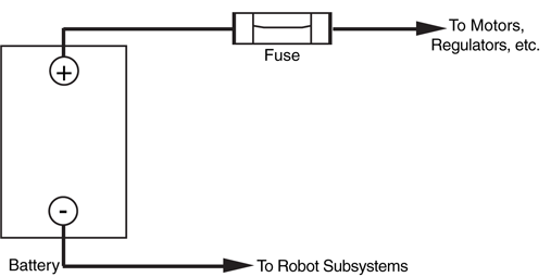
Flashlight batteries don’t deliver extraordinary current, so fuse protection is not required on
the most basic robot designs. Gel-cell, lead-acid, and high-capacity NiCad batteries can
deliver a most shocking amount of current. In fact, if the leads of the battery accidentally
touch each other or there is a short in the circuit, the wires may melt and a fire could erupt.
Fuse protection helps eliminate the calamity of a short circuit or power overload in your
robot. As illustrated in Fig. 17-6, connect the fuse in line with the positive rail of the battery,
as near to the battery as possible. You can purchase fuse holders that connect directly
to the wire or that mount on a panel or printed circuit board.
Choosing the right value of fuse can be a little tricky, but it is not impossible. It does
require that you know how much current your robot draws from the battery during normal
and stalled motor operation. You can determine the value of the fuse by adding up the current
draw of each separate subsystem, then add 40 to 60 percent contingency for overcurrents
above and beyond the measured requirements. These “overcurrents” usually consist
of extra motor draws when the robot first starts moving or encounters an obstacle or hill it
must climb over—if the motors are stalled, then current draw will be much greater than 50
percent over the nominal operating value, causing the fuse to blow and protecting the robot
and its systems.
For example, if the two drive motors in a robot draw 2 A each, the main circuit board
draws 1 A, and four other small motors each draw 0.5 A (for a total of, perhaps, 2 A). Add
all these up and you get 7 A. Installing a fuse with a rating of 7 A at 125 V will probably
end up blowing when the robot starts moving or encounters a bump in the carpet. Putting
in a 10- to 12-A fuse will give the extra margin to handle extra current draw during normal
operation.
To help prevent the initial motor current draw, you should use a slow-blow fuse. Otherwise,
the fuse will burn out every time one of the heavy-duty motors kicks in.
Fuses don’t come in every conceivable size. For the sake of standardization, choose the
regular 1¼-in-long-by-¼-in-diameter bus fuses. You’ll have an easier job finding fuse holders
for them and a greater selection of values. Even with a standard fuse size, there is not much
to choose from past 8 A, other than 10, 15, and 20 A. For values over 8 A, you may
have to go with ceramic fuses, which are used mainly for microwave ovens and kitchen
appliances.
Some advanced robot designs require several voltages if they are to operate properly. The
drive motors may require 12 V, at perhaps 2 to 4 A, whereas the electronics require +5,
and perhaps even -5 V. Multiple voltages can be handled in several ways. The easiest and
most straightforward is to use a different set of batteries for each main subsection. The
motors operate off one set of large lead-acid or gel-cell batteries; the electronics are driven
by smaller capacity NiMH batteries.
This approach is actually preferable when the motors used in the robot draw a lot of current.
Motors naturally distribute a lot of electrical noise throughout the power lines, noise
that electronic circuitry is extremely sensitive to. The electrical isolation that is provided
when you use different batteries virtually eliminates problems caused by noise (the remainder
of the noise problems occur when the motor commutators arc, causing RF interference).
In addition, when the motors are first started, the excessive current draw from the
motors may zap all the juice from the electronics. This sag can cause failed or erratic behavior,
and it could cause your robot to lose control.
The other approach to handling multiple voltages is to use one main battery source and
a voltage regulator to step it up or down so it can be used with the various components in the system. This is called DC-DC conversion and will be discussed later in this chapter. You
can accomplish DC-DC conversion by using circuits of your own design or by purchasing
specialty integrated circuit chips that make the job easier. One battery’s output voltage can
be changed to a wide range of voltages from zero to about 15 V. Normally a single battery
will directly drive the motors and, with proper conversion, supply the +5-V power to the circuit
boards.
Connecting the batteries judiciously can also yield multiple voltage outputs. By connecting
two 6-V batteries in series, as shown in Fig. 17-7, you get +12 V, +6 V, and -6 V. This
system isn’t nearly as foolproof as it seems, however. More than likely, the two batteries will
not be discharged at the same rate. This causes extra current to be drawn from one to the
other, and the batteries may not last as long as they might otherwise.
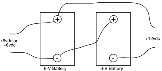
Figure 17-7 Various voltage tap-offs from two 6-V batteries. This is not an ideal
approach (as the batteries will discharge at different rates).
If all of the subsystems in your robot use the same batteries, be sure to add sufficient filtering
capacitors across the positive and negative power rails. The capacitors help soak up
excessive current spikes and noise, which are most often contributed by motors. Place the
capacitors as near to the batteries and the noise source as possible. A good rule of thumb
is 100 μF of capacitance for every 250 mA of current drawn by a motor during normal
operation.
Be certain the capacitors you use are overrated above the voltage by 50 to 75 percent
(e.g., use a 7.5-V rated capacitor for a 5-V circuit; 25 to 35 V is fine). An underrated capacitor
will probably burn out or possibly develop a short circuit, which can cause a fire.
You should place smaller value capacitors, such as 0.01 to 0.1 μF, across the positive
and negative power rails wherever power enters or exits a circuit board. As a general rule,
you should add one of these decoupling capacitors at the power input pins of all ICs. Linear
ICs, such as the 555 timer, need decoupling capacitors, or the noise they generate
through the power lines can ripple through to other circuits.
Most hobby robots now contain computer-based control electronics of some type. The
computer requires a specific voltage (called regulation, discussed in the next section), and the chip requires that the voltage be clean and free of noise and other glitches. A common
problem in robotic systems is that the motors cause so-called sags and noise in the power
supply system, which can affect the operation of the control electronics. You can largely
remedy this by using separate battery supplies for the motors and the electronics. The
ground connection of the power supplies must be connected together and common
throughout the robot.
With this setup, the motors have one unregulated power supply, and the control electronics
have their own regulated power supply. Even if the motors turn on and off very
rapidly, this approach will minimize sags and noise on the electronics side. It’s not always
possible to have separate battery supplies, of course. In these cases, use the capacitor filtering
techniques described previously. The large capacitors that are needed to achieve
good filtering between the electronics and motor sections will increase the size and weight
of your robot. A 2200-μF capacitor, for example, may measure  in diameter by over an
inch in height. You should plan for this in your design.
in diameter by over an
inch in height. You should plan for this in your design.
in diameter by over an
inch in height. You should plan for this in your design.Many types of electronic circuits require a precise voltage or they may be damaged or act
erratically. Generally, you provide voltage regulation only to those components and circuit
boards in your robot that require it. You can easily add a variety of different solid-state voltage
regulators to your electronic circuits. They are easy to obtain, and you can choose from
among several styles and output capacities. In this chapter, some of the different types will
be described along with their operating characteristics.
A quick and relatively small method for providing regulated voltage is to use zener diodes,
as shown in Fig. 17-8. With a zener diode, current does not begin to flow through the load
circuitry until the voltage exceeds a certain level (called the breakdown voltage). Voltage
over this level is then “shunted” through the zener diode, effectively limiting the voltage to
the rest of the circuit. Zener diodes are available in a variety of voltages, such as 3.3, 5.1,
6.2, and others.
Zener diodes are also rated by their tolerance (1 percent and 5 percent are common) and
their power rating, in watts. Note the resistor in the schematic shown in Fig. 17-8. This
resistor (R1) limits the current through the zener, and its value (and wattage) is determined
by the current draw from the load, as well as the input and output voltages.
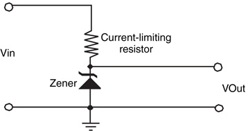
Figure 17-8 A zener diode and
resistor can make a simple and inexpensive
voltage regulator. Be sure to
select the proper wattage for the
zener and the proper wattage and
resistance for the resistor.
The process of determining the correct values and ratings for resistor R1 and the zener
diode is fairly simple and uses the basic electricity rules presented earlier in the book. The
zener voltage rating is, quite obviously, the desired regulated voltage—you may find that the
available rated voltages are somewhat awkward (such as 5.1 V), but you should be able to
find a value within a few percent of the rated value.
Once you know the voltage rating for the zener diode that you are going to use, you can
then calculate the value and ratings for R1. The zener diode regulator shown in Fig. 17-8 is
actually a voltage divider, with the lower portion being a set voltage level. To determine the
correct resistance of R1, you have to know what the input voltage is and the current that is
going to be drawn from the regulator. For example, if you wanted 100 mA at 5.1 V from
a 12-V power supply, the resistance of R1 can be calculated as:
VR1  = 12V - 5.1V = 6.9V

 R  = V / i


    = 6.9 V / 0.100 A


    = 69 Ω
The closest “standard” resistor value you can get is 68 Ω, which will result in 101 mA being
available for the load. With this value in hand, you can now calculate the power being dissipated
by the resistor, using the basic power formulas:
Power = V × i

      = 6.9 V × 0.101 A

      = 0.7 Watts
Standard resistor power ratings are in  ,
,  ,
,  , 1, 2, and so on watts. A 1-W, 68 Ω resistor
would be chosen for this application.
, 1, 2, and so on watts. A 1-W, 68 Ω resistor
would be chosen for this application.
, , , 1, 2, and so on watts. A 1-W, 68 Ω resistor
would be chosen for this application.The zener diode will also be dissipating power; how much is something that you should
decide. To err on the side of safety, it is recommended that you assume that the zener diode
can have 100 percent of the load current passing through it (when the load circuitry is not
attached to the power supply). The power rating for the zener diode is calculated exactly the
same way as R1:
Power = V × i

      = 5.1 V × 0.101A

      = 0.52 Watts
For this application, you could probably get away with a W rated zener diode along with
the 1 W rated 68 Ω resistor. Working with zener diodes to make power supplies is quite
easy, but there is a tremendous price to pay in terms of lost power. In this example, the total
power dissipated will be 1.2 W, with 58 percent of it being dissipated through the R1 resistor.
This loss may be unacceptable in a battery-powered robot.
W rated zener diode along with
the 1 W rated 68 Ω resistor. Working with zener diodes to make power supplies is quite
easy, but there is a tremendous price to pay in terms of lost power. In this example, the total
power dissipated will be 1.2 W, with 58 percent of it being dissipated through the R1 resistor.
This loss may be unacceptable in a battery-powered robot.The zener diode regulator can be thought of as a tub of water with a hole at the bottom; the
maximum pressure of the water squirting out is dependent on the level of water in the tub.
Ideally, there should be more water coming into the tub than will be ever drawn to ensure
that the pressure of the water coming out of the hole is constant. This means that a fair
amount of water will spill over the edge of the tub. As was shown in the previous section,
this is an extremely inefficient method of providing a regulated voltage, as the electrical
equivalent of the water pouring over the edge is the power dissipated by R1.
To improve upon the zener diode regulator’s inefficiency, a voltage regulator that just lets
out enough current at the regulated voltage is desired. The linear voltage regulator only
allows the required current (at the desired voltage) out and works just like a car’s carburetor.
In a carburetor, fuel is allowed to flow as required by the engine—if less is required than is
available, a valve closes and reduces the amount of fuel that is passed to the engine. The linear
voltage regulator works in an identical fashion: an output transistor in the regulator circuit
only allows the required amount of current to the load circuit.
The actual circuitry that implements the linear regulator is quite complex, but this is
really not a concern of yours as it is usually contained within a single chip like the one
shown in Fig. 17-9. The circuit shown here uses one of the most popular linear voltage regulators,
the 7805 to regulate a high-voltage source to +5 V for digital electronic circuitry.
The parts required for the 7805 based linear regulator are listed in Table 17-1.

Figure 17-9 Three-terminal linear voltage regulators, like the 7805, can be used to
provide stable voltages for battery-powered robots. The capacitors help filter (smooth out)
the voltage.
IC1 |
7805 linear voltage regulator |
C1 |
100 μF electrolytic capacitor |
C2, C3 |
0.1 μF capacitor (any type) |
Two of the most popular voltage regulators, the 7805 and 7812, provide +5 and +12
V, respectively. Other 7800 series power regulators are designed for +15, +18, +20, and
+24 V. The 7900 series provides negative power supply voltages in similar increments. The
current capacity of the 7800 and 7900 series that come in the TO-220 style transistor
packages (these can often be identified as they have no suffix or use a “T” suffix in their part
number) is limited to less than 1 A. As a result, you must use them in circuits that do not
draw in an excess of this amount.
Other linear regulators are available in a more traditional TO-3-style transistor package
(“K” suffix) that offers current output to several amps. The “L” series regulators come in the
small TO-92 transistor packages and are designed for applications that require less than
about 500 mA. The different packages limit the amount of heat that can be dissipated by
the linear regulators and determine how much current they can source.
Here are some other linear regulators that you may be interested in:
- The 328K provides an adjustable output to 5 V, with a maximum current of 5 A (amperes).
- The 78H05K offers a 5-V output at 5 A.
- The 78H12K offers a 12-V output at 5 A.
- The 78P05K delivers 5 V at 10 A.
An important point to note about linear voltage regulators is their dropout voltage, or
the minimum voltage that must be provided to operate properly. For the 7800 series, you
should provide a minimum of 3 V more than they are rated at. So for a 7805, 8 V or more
must be provided to the chip to get 5 V out. This dropout is effectively a voltage drop within
the chip. For an 8 V input to the 7805, 37.5 percent of the power passed to the chip will
be dissipated as heat; better than the zener diode regulator, but still a significant amount of
power loss. If you were to look around, you will find linear regulator chips with much
smaller dropout voltages, which will minimize the power lost significantly.
The regulators described in the previous two sections are not very efficient; they reduce the
input voltage in some way, which means they have to dissipate the resulting power lost in
the regulator. The switching voltage regulator (more accurately called the switch mode
power supply, also known by its acronym SMPS) has much higher operating efficiencies
and can be configured to raise the incoming voltage or produce a negative voltage output.
The basic circuit for a switching voltage regulator is shown in Fig. 17-10 with its operating
waveform shown in Fig. 17-11. This circuit is designed to raise the input voltage from
3 to 5 V by loading and unloading an inductor (or coil) and passing the high voltage to a
diode and a filter capacitor. When the transistor attached to the coil is turned off, the coil
reacts by producing a large voltage that passes some current through the diode to the load
circuit. The VCO, or voltage controlled oscillator, controls the rate at which the inductor’s
transistor is turned on and off to ensure the voltage is regulated reasonably well.


Figure 17-11 The waveforms within the switching voltage regulator at the points
labeled in Fig. 17-10.
The design of the VCO and the specification of the transistor switching waveform are
fairly complex (although not as complex as you might think—many simple microcontrollers
on the market can monitor the output voltage and calculate a new transistor switching
waveform quite easily). Fortunately, there are a lot of controller chips, such as the LTC1174CN8-5, shown in Fig. 17-12. This chip will take a voltage from 3 to 15 V and
produce a regulated 5 V output with an efficiency well over 90 percent.
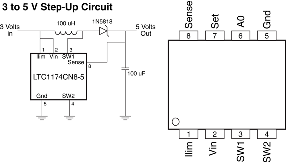
Figure 17-12 An LTC1174CN8-5 switching regulator circuit that will regulate an incoming
voltage of 3 to 15 V to 5 V with a maximum current of 100 mA.
The wide input voltage range is part of the advantage of using a switching voltage regulator
for robot applications in which a single battery is used for driving the motors as well as
the electronics. The switching voltage regulator will produce a remarkably constant output
voltage despite the varying input voltage caused by the robot’s motors starting, stopping, or
stalling. When specifying the circuit to be used in your robot, the nominal voltage output of
the batteries while the motors are running should be used.
Switching voltage regulators are a bit more complex to wire, and, depending on the
application and the amount of current required for the robot’s electronics, will require
more than the four components used in the power supply shown in Fig. 17-12. Even if
the LTC1174CN8-4 was to be used in a robot application, you would be well advised to
pass the incoming electrical power through a diode and filter the diode’s output (and input
to the voltage regulator) using a 47 μF capacitor or more to ensure that the power would
be constant even when there are large voltage transients caused by the motor’s changing
state.
Switching voltage regulators do not cost much more than the zener diode regulator or
linear regulators presented in the previous sections; a big part of the cost of the other regulators
is the heat sinking and costs of large current components used in them. The switching
voltage regulator does not generate a significant amount of heat due to its high
operating efficiency and does not need the same expensive packaging or heat sinking of the
other solutions.
You may choose to place all or most of your robot’s electronic components on a single
board. You can mount the regulator(s) directly on the board. You can also have several
smaller boards share one regulator as long as the boards together don’t pull power in excess
of what the regulator can supply. Fig. 17-13 shows how to distribute the power from a single
battery source to many separate circuit boards. The individual regulators provide power
for one or two large boards or a half dozen or so smaller ones.

Figure 17-13 Parallel connection of circuit boards from a single power source. Each
board has its own voltage regulator.
Quick! What’s the condition of the battery in your robot? With a battery monitor, you’d
know in a flash. A battery monitor continually samples the output voltage of the battery during
operation of the robot (the best time to test the battery) and provides a visual or logic
output. In this section some of the most common types are described.
Fig. 17-14 (refer to the parts list in Table 17-2) shows a simple battery monitor using a 4.3-
V quarter-watt zener diode. R1 sets the trip point. When in operation, the LED winks off
when the voltage drops below the setpoint. To use the monitor, set R1 (which should be a
precision potentiometer, 1 or 3 turn) when the batteries in your robot are low. Adjust the
pot carefully until the LED just winks off. Recharge the batteries. The LED should now light. Another, more “scientific” way to adjust R1 is to power the circuit using an adjustable power
supply. While watching the voltage output on a meter, set the voltage at the trip point (e.g.,
for a 12-V robot, set it to about 10 V).
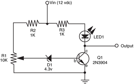
Figure 17-14 Battery monitor using 4.3-V zener diode. This circuit
is designed to be used with a 12-V battery.
R1 |
10K potentiometer (see text) |
R2, R3 |
1K resistor |
D1 |
4.3-V zener diode (¼-W) |
Q1 |
2N3904 NPN transistor |
LED1 |
Light-emitting diode |
A microprocessor-compatible battery monitor is shown in Fig. 17-15 (refer to the parts list
in Table 17-3). This monitor uses a 5.1-V quarter-watt zener as a voltage reference for a
339 quad comparator IC. Only one of the comparator circuits in the IC is used; you are free
to use any of the remaining three for other applications. The circuit is set to trip when the
voltage sags below the (approximate) 5-V threshold of the zener (in my test circuit the comparator
tripped when the supply voltage dipped to under 4.5 V). When this happens, the
output of the comparator immediately drops to 0 V. Note that the outputs of the 339 are
open collector; R2 pulls up the output so a voltage change can be observed.
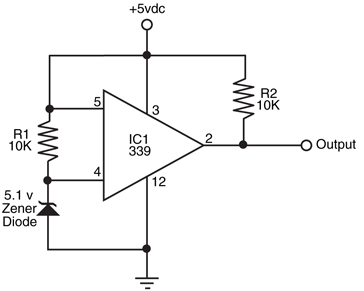
Figure 17-15 A
zener diode and 339
comparator can be used
to construct a fairly accurate
5-V battery monitor.
IC1 |
339 comparator IC |
R1, R2 |
10K resistor |
D1 |
5.1-V zener diode (¼- or ½-W) |
You can usually connect battery monitors to a microprocessor or microcontroller input.
When in operation, the microprocessor is signaled by the interrupt when the LED is triggered.
Software running on the computer interprets the interrupt as “low battery; quick get
a recharge.” The robot can then place itself into nest mode, where it seeks out its own battery
charger. If the charger terminals are constructed properly, it’s possible for the robot to
plug itself in. Fig. 17-16 shows a simplified flowchart illustrating how this might work.
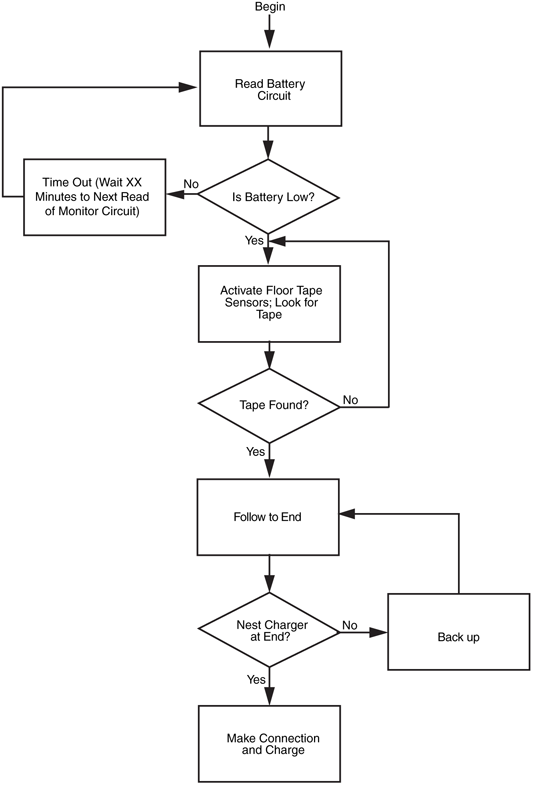
Figure 17-16 Software can be used to command the robot to return to its battery
recharger nest should the battery exceed a certain low point.
In the previous editions of this book, a great deal of space and effort was devoted to creating
a power supply to eliminate the need for supplying the needs of a robot from a battery
during development and testing. The circuit rectified and regulated 110 V AC from a household
wall socket to +5 V using a 7805. This circuit replicated the capabilities of the logic
power supply already built into the robot but probably did not provide enough current to
drive the robot’s motors. In this edition, a step back is taken with a look at a more practical
and easier method of powering a robot on a bench or during development by using commonly
available “wall wart” or laptop power supplies.
Wall wart is the term used by most people to describe wall-mounted AC/DC power converters
to provide power to a variety of different tasks, from powering boom boxes, to toys
and game systems, to telephones and other appliances. Chances are you have a number
around the house left over from electronic devices that no longer work or have been lost.
They can probably be adapted to power your robot’s electronics and even motors (if they
can produce enough current) with no modifications. Even if you don’t, one can be picked
up at a local convenience store for just a couple of dollars.
The important feature to look for in these power supplies is that they have a power plug
on them rather than a phono plug. A phono plug is a single shaft of metal, with multiple
connections built into it at different intervals and was originally designed for providing headphone
connections to a radio or other audio device. A stereo headset phono plug will have
a tip that is separate from a metal band just after it and the main body of the shaft. A power
plug consists of a hollow barrel that has a power connection on the inside separate from
the one on the outside. The phono plug can be used for providing power, but you will find
that there is some arcing or sparks when the plug is inserted or withdrawn.
The power plug does not cause arcing or sparks when plugged in or withdrawn from
the socket because there is no opportunity for the positive voltage and ground to be
shorted together as is shown in Fig. 17-17. When the plug is inserted, the center hole,
which provides positive voltage, comes into contact with the central post of the socket and
the outside ground connection contacts a metal wiper. The size of a power plug is determined
by the diameter or the central post of the plug—2.5 mm is probably the most common
size used.
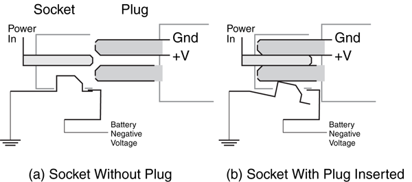
Figure 17-17 Power plug and socket combination being shown (a) separate and (b) plug
inserted. When the plug is inserted, the wiper connection is broken and the negative voltage connection
to the internal battery can be automatically disconnected, eliminating its ability to power
the robot.
Note that in Fig. 17-17, the negative voltage from the battery passes through a metal
connection to the ground wiper, which is disconnected when the plug is inserted. Using this
feature will allow the battery to be kept in the robot while external power is being provided.
Looking around, you will find that the most current the typical wall wart power supply
can provide is about 800 mA. This is probably not going to be adequate for larger robots. Instead of the small wall wart, you should be able to find an old laptop power supply, like
the one shown in Fig. 17-18, which provides 12 V at up to 5 A at a surplus store for $5 or
so. These connectors are in the power plug format but are much larger than the ones typically
used for CD players and basic home electronics. Some laptop power supplies provide
multiple voltage outputs that may be useful in your robot.
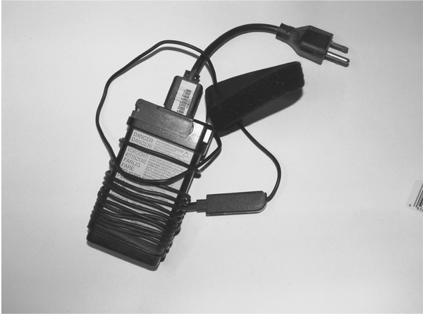
Figure 17-18 A used laptop power supply can be purchased for just a few dollars
and provides several amps of current.
Finally, the DC output from the power supplies cannot be used to charge batteries.
NiMH, NiCad, and other battery technologies require a PWM input and often have testing
algorithms to determine when they are fully (and not over) charged. Damage or fire could
result if a straight DC voltage is passed to them, so only use chargers that are designed for
the type of battery you are using.
To learn more about . . . |
Read |
|
Understanding motor current ratings |
Chapter 19, “Choosing the Right Motor for the
Job” |
|
Other power systems (e.g., hydraulic |
Chapter 26, “Reaching Out with Arms” |