CHOOSING THE
RIGHT MOTOR
RIGHT MOTOR
Motors are the muscles of robots. Attach a motor to a set of wheels and your robot
can scoot around the floor. Attach a motor to a lever, and the shoulder joint for your
robot can move up and down. Attach a motor to a roller, and the head of your robot can
turn back and forth, scanning its environment. There are many kinds of motors; however,
only a select few are truly suitable for home-brew robotics. This chapter will examine the
various types of motors and how they are used.
Direct current—DC—dominates the field of robotics, either mobile or stationary. DC is used
as the main power source for operating the on-board electronics, for opening and closing
solenoids, and, yes, for running motors. Few robots use motors designed to operate from
AC, even those automatons used in factories. Such robots convert the AC power to DC,
then distribute the DC to various subsystems of the machine.
DC motors may be the motors of choice, but that doesn't mean you should use just any
DC motor in your robot designs. When looking for suitable motors, be sure the ones you
buy are reversible. Few robotic applications call for just unidirectional (one-direction)
motors. You must be able to operate the motor in one direction, stop it, and change its
direction. DC motors are inherently bidirectional, but some design limitations may prevent
reversibility.
The most important factor is the commutator brushes. If the brushes are slanted, the
motor probably can't be reversed. In addition, the internal wiring of some DC motors prevents
them from going in any but one direction. Spotting the unusual wiring scheme by just
looking at the exterior or the motor is difficult, at best, even for a seasoned motor user.
The best and easiest test is to try the motor with a suitable battery or DC power supply.
Apply the power leads from the motor to the terminals of the battery or supply. Note the
direction of rotation of the motor shaft. Now, reverse the power leads from the motor. The
motor shaft should rotate in reverse.
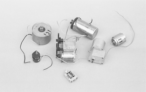
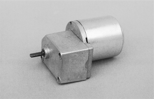
DC motors can be either continuous or stepping. Here is the difference: with a continuous
motor, like the ones in Fig. 19-1, the application of power causes the shaft to rotate continually.
The shaft stops only when the power is removed or if the motor is stalled because
it can no longer drive the load attached to it.
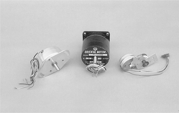
With stepping motors, shown in Fig. 19-2, the application of power causes the shaft to
rotate a few degrees, then stop. Continuous rotation of the shaft requires that the power be
pulsed to the motor. As with continuous DC motors, there are subtypes of stepping motors.
Permanent magnet steppers are the ones you're likely to encounter, and they are also the
easiest to use.
The design differences between continuous and stepping DC motors need to be
addressed in detail. Chapter 20, "Working with DC Motors," focuses entirely on continuous motors. Chapter 21, "Working with Stepper Motors," focuses entirely on the stepping variety.
Although these two chapters focus on the main drive motors of your robot, you can
apply the information to motors used for other purposes as well.
A special subset of continuous motors is the servo motor, which in typical cases combines
a continuous DC motor with a feedback loop to ensure the accurate positioning of the
motor. A common form of servo motor is the kind used in model and hobby radio-controlled
(R/C) cars and planes.
R/C servos are in plentiful supply, and their cost is reasonable (about $10 to $12 for
basic units). Though R/C servos are continuous DC motors at heart, we will devote a separate
chapter is devoted just to them. See Chapter 21, "Working with Servo Motors," for
more information on using R/C servo motors not only to drive your robot creations across
the floor but to operate robot legs, arms, hands, heads, and just about any other appendage.
There are many other types of motors, some of which may be useful in your hobby robot,
some of which will not. DC, stepper, and servo motors are the most common, but you may
also see references to some of the following:
- Brushless DC. This is a kind of DC motor that has no brushes. It is controlled electronically. Brushless DC motors are commonly used in fans inside computers and for motors in VCRs and videodisc players.
- Switched reluctance. This is a DC motor without permanent magnets.
- Synchronous. Also known as brushless AC, this motor operates synchronously with the phase of the power supply current. These motors function much like stepper motors, which will be discussed in Chapter 21.
- Synchro. These motors are considered distinct from the synchronous variety described previously. Synchro motors are commonly designed to be used in pairs, where a "master" motor electrically controls a "slave" motor. Rotation of the master causes an equal amount of rotation in the slave.
- AC induction. This is the ordinary AC motor used in fans, kitchen mixers, and many other applications.
- Sel-Syn. This is a brand name, often used to refer to synchronous AC motors.
Note that AC motors aren't always operated at 50/60 Hz, which is common for household
current. Motors for 400 Hz operation, for example, are common in surplus stores and
are used for both aircraft and industrial applications.
Motors come with extensive specifications. The meaning and purpose of some of the specifications
are obvious; others aren't. Let's take a look at the primary specifications of
motors–;voltage, current draw, speed, and torque–;and see how they relate to your robot
designs.
All motors are rated by their operating voltage. With small DC hobby motors, the rating is
actually a range, usually 1.5 to 6 V. Some high-quality DC motors are designed for a specific
voltage, such as 12 or 24 V. The kinds of motors of most interest to robot builders are
the low-voltage variety–;those that operate at 1.5 to 12 V.
Most motors can be operated satisfactorily at voltages higher or lower than those specified.
A 12-V motor is likely to run at 8 V, but it may not be as powerful as it could be and
it will run slower (an exception to this is stepper motors; see Chapter 21, "Working with
Stepper Motors," for details). You'll find that most motors will refuse to run, or will not run
well, at voltages under 50 percent of the specified rating.
Similarly, a 12-V motor is likely to run at 16 V. As you may expect, the speed of the
shaft rotation increases, and the motor will exhibit greater power. I do not recommend that
you run a motor continuously at more than 30 or 40 percent its rated voltage, however.
The windings may overheat, which may cause permanent damage. Motors designed for
high-speed operation may turn faster than their ball-bearing construction allows.
If you don't know the voltage rating of a motor, you can take a guess at it by trying various voltages and seeing which one provides the greatest power with the least amount of
heat dissipated through the windings (and felt on the outside of the case). You can also listen
to the motor. It should not seem as if it is straining under the stress of high speeds.
Current draw is the amount of current, in milliamps or amps, that the motor requires from
the power supply. Current draw is more important when the specification describes motor
loading, that is, when the motor is turning something or doing some work. The current
draw of a free-running (no-load) motor can be quite low. But have that same motor spin a
wheel, which in turn moves a robot across the floor, and the current draw jumps 300, 500,
even 1000 percent.
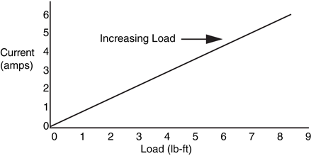
With most permanent magnet motors (the most popular kind), current draw increases
with load. You can see this visually in Fig. 19-3. The more the motor has to work to turn
the shaft, the more current is required. The load used by the manufacturer when testing the
motor isn't standardized, so in your application the current draw may be more or less than
that specified.
A point is reached when the motor does all the work it can do, and no more current will
flow through it. The shaft stops rotating; the motor has stalled. Some motors, but not many,
are rated (by the manufacturer) by the amount of current they draw when stalled.
This is considered the worst-case condition. The motor will never draw more than this
current unless it is shorted out, so if the system is designed to handle the stall current it can
handle anything. Motors rated by their stall current will be labeled as such. Motors designed
for the military, available through surplus stores, are typically rated by their stall current.
When providing motors for your robots, you should always know the approximate current
draw under load. Most volt-ohm meters can test current. Some special-purpose amp meters
are made just for the job.
Be aware that some volt-ohm meters can't handle the kind of current pulled through a
motor. Many digital meters can't deal with more than 200 to 400 mA of current in the low-current
settings. Small hobby motors can often draw in excess of this. Be sure your meter
can accommodate current up to 5 or 10 A and is fuse protected.
If your meter cannot register this high without popping fuses or burning up, insert a
1- to 10- Ω power resistor (10 to 20 W) between one of the motor terminals and the positive
supply rail, as shown in Fig. 19-4. With the meter set on DC voltage, measure the voltage
developed across the resistor.
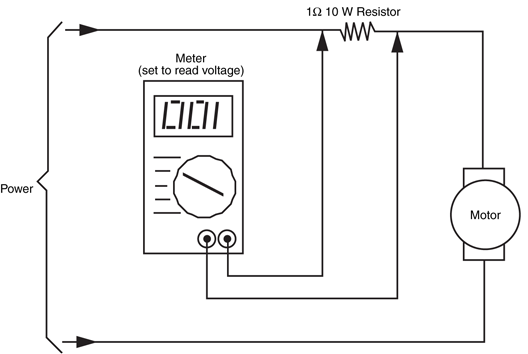
Figure 19-4 How to test the current draw of a motor by measuring the voltage
developed across an in-line resistor. The actual value of the resistor can vary, but it
should be under about 20 . Be sure the resistor is a high-wattage type.
A bit of Ohm's law, I = E/R (I is current, E is voltage, R is resistance) reveals the current
draw through the motor. For example, if the resistance is 10 Ω and the voltage is 2.86 V,
the current draw is 286 mA. You can watch the voltage go up (and therefore the current,
too) by loading the shaft of the motor.
When you are actually measuring voltage across and the current through a motor, you
will probably see your readings jump around quite a bit (especially if you are adding a load
to your motor). When you are calculating the load of the motor, make sure that you use the
worst-case (highest) value for current and the no-load (motor disconnected) voltage of your
power supply to ensure that you provide enough power to your application.
The rotational speed of a motor is given in revolutions per minute (r/min). Most continuous
DC motors have a normal operating speed of 4000 to 7000 r/min. However, some special-purpose
motors, such as those used in tape recorders and computer disk drives, operate as
slow as 2000 to 3000 r/min. For just about all robotic applications, these speeds are much
too high. You must reduce the speed to no more than 150 r/min (even less for motors driving
arms and grippers) by using a gear train. You can obtain some reduction by using electronic
control, as described in Part 5 of this book, "Computers and Electronic Control." However, such control is designed to make fine-tuned speed adjustments, not reduce the
rotation of the motor from 5000 to 50 r/min. Gears, which are explained in later sections
of this chapter, are used to provide these large reductions in rotation speeds.
Note that the speed of stepping motors is not rated in r/min but in steps (or pulses) per
second. The speed of a stepper motor is a function of the number of steps that are required
to make one full revolution plus the number of steps applied to the motor each second. As
a comparison, the majority of light–; and medium-duty stepper motors operate at the equivalent
of 100 to 140 r/min. See Chapter 21, "Working with Stepper Motors," for more
information.
Torque is the force the motor exerts upon its load. The higher the torque, the larger the load
can be and the faster the motor will spin under that load. Reduce the torque, and the motor
slows down, straining under the workload. Reduce the torque even more, and the load may
prove too demanding for the motor. The motor will stall to a grinding halt, and in doing so
eat up current (and put out a lot of heat).
Torque is perhaps the most confusing design aspect of motors. This is not because there
is anything inherently difficult about it but because motor manufacturers have yet to settle
on a standard means of measurement. Motors made for industry are rated one way, motors
for the military another.
At its most basic level, torque is measured by attaching a lever to the end of the motor
shaft and a weight or gauge on the end of that lever, as depicted in Fig. 19-5. The lever can
be any number of lengths: 1 cm, 1 in, or 1 ft. Remember this because it plays an important
role in torque measurement. The weight can either be a hunk or lead or, more commonly,
a spring-loaded scale (as shown in the figure). Turn the motor on and it turns the lever. The
amount of weight it lifts is the torque of the motor. There is more to motor testing than this,
of course, but it'll do for the moment.
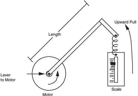
Figure 19-5 The torque of a motor is measured by attaching a
weight or scale to the end of a lever and mounting the lever of the motor
shaft.
Now for the ratings game. Remember the length of the lever? That length is used in the
torque specification. If the lever is 1 in long, and the weight successfully lifted is 2 oz, then
the motor is said to have a torque of 2 oz-in. (Some people reverse the "ounce" and
"inches" and come up with "inch-ounces.")
The unit of length for the lever usually depends on the unit of measurement given for the
weight. When the weight is in grams, the lever is in centimeters (gm-cm). When the weight
is in ounces, as already seen, the lever used is in inches (oz-in). Finally, when the weight is
in pounds, the lever used is commonly in feet (lb-ft). Like the ounce-inch measurement,
gram-centimeter and pound-foot specifications can be reversed—"centimeter-gram" or
"foot-pound." Note that these easy-to-follow conventions aren't always used. Some motors
may be rated by a mixture of the standards—ounces and feet or pounds and inches.
Most motors are rated by their running torque, or the force they exert as long as the shaft
continues to rotate. For robotic applications, it's the most important rating because it determines
how large the load can be and still guarantee that the motor turns. How running
torque tests are conducted varies from one motor manufacturer to another, so results can differ. The tests are impractical to duplicate in the home shop, unless you have an elaborate
slip-clutch test stand, precision scale, and sundry other test jigs.
If the motor(s) you are looking at doesn't have running torque ratings, you must estimate
its relative strength. This can be done by mounting it on a makeshift wood or metal platform,
attaching wheels, and having it scoot around the floor. If the motor supports the platform,
start piling on weights. If the motor continues to operate with, say, 40 or 50 lb of junk
on the platform, you've got an excellent motor for driving your robot.
Some motors you may test aren't designed for hauling heavy loads, but they may be suitable
for operating arms, grippers, and other mechanical components. You can test the relative
strength of these motors by securing them in a vise, then attaching a large pair of
Vise-Grips or other lockable pliers to them. Use your own hand as a test jig, or rig one up
with fishing weights. Determine the rotational power of the motor by applying juice to the
motor and seeing how many weights it can successfully handle.
Such crude tests make more sense if you have a standard by which to judge others. If
you've designed a robotic arm before, for example, and are making another one, test the
motors that you successfully used in your prototype. If subsequent motors fail to match or
exceed the test results of the standard, you know they are unsuitable for the test.
Another torque specification, stall torque, is sometimes provided by the manufacturer
instead of or in addition to running torque (this is especially true of stepping motors). Stall
torque is the force exerted by the motor when the shaft is clamped tight. There is an indirect
relationship between stall torque and running torque, and although it varies from motor
to motor you can use the stall torque rating when you select candidate motors for your robot
designs.
We've already discussed the fact that the normal running speed of motors is far too fast for
most robotics applications. Locomotion systems need motors with running speeds of 75 to
150 r/min. Any faster than this, and the robot will skim across the floor and bash into walls
and people. Arms, gripper mechanisms, and most other mechanical subsystems need even
slower motors. The motor for positioning the shoulder joint of an arm needs to have a
speed of less than 20 r/min; 5 to 8 r/min is even better.
There are two general ways to decrease motor speed significantly: build a bigger motor
(impractical) or add gear reduction. Gear reduction is used in your car, on your bicycle, in
the washing machine and dryer, and in countless other motor-operated mechanisms.
Gears perform two important duties. First, they can make the number of revolutions
applied to one gear greater or lesser than the number of revolutions of another gear that is
connected to it. They also increase or decrease torque, depending on how the gears are oriented.
Gears can also serve to simply transfer force from one place to another.
Gears are actually round levers, and it may help to explain how gears function by first
examining the basic mechanical lever. Place a lever on a fulcrum so the majority of the lever
is on one side. Push up on the long side, and the short side moves in proportion. Although
you may move the lever several feet, the short side is moved only a few inches. Also note
that the force available on the short end is proportionately larger than the force applied on
the long end. You use this wonderful fact of physics when you dig a rock out of the ground
with your shovel or jack up your car to replace a tire.
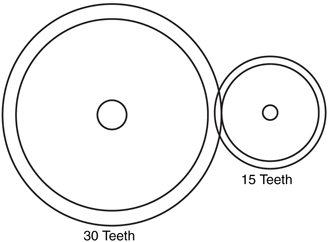
Now back to gears. Attach a small gear to a large gear, as shown in Fig. 19-6. The small
gear is directly driven by a motor. For each revolution of the small gear, the large gear turns
one-half a revolution. Expressed another way, if the motor and small gear turn at 1000
r/min, the large gear turns at 500 r/min. The gear ratio is said to be 2:1.
Note that another important thing happens, just as it did with the lever and fulcrum.
Decreasing the speed of the motor also increases its torque. The power output is approximately
twice the input. Some power is lost in the reduction process due to the friction of the
gears. If the drive and driven gears are the same size, the rotation speed is neither increased
nor decreased, and the torque is not affected (apart from small frictional losses). You can use
same-size gears in robotics design to transfer motive power from one shaft to another, such
as driving a set of wheels at the same speed and in the same direction.
Gears are an old invention, going back to ancient Greece. Today's gears are more refined,
and they are available in all sorts of styles and materials. However, they are still based on
the old Greek design in which the teeth from the two mating gears mesh with each other.
The teeth provide an active physical connection between the two gears, and the force is
transferred from one gear to another.
Gears with the same size teeth are usually characterized not by their physical size but by
the number of teeth around their circumference. In the example in Fig. 19-6, the small
gear contains 15 teeth, the large gear 30 teeth. And, you can string together a number of
gears one after the other, all with varying numbers of teeth (see Fig. 19-7). Attach a
tachometer to the hub of each gear, and you can measure its speed. You'll discover the following
two facts:
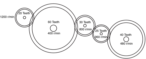
Figure 19-7 Gears driven by the 20-tooth gear on the left rotate at different speeds,
depending on their diameter.
- The speed always decreases when going from a small to a large gear.
- The speed always increases when going from a large to a small gear.
There are plenty of times when you need to reduce the speed of a motor from 5000 to
50 r/min. That kind of speed reduction requires a reduction ratio of 100:1. To accomplish
that with just two gears you would need, as an example, a drive gear that has 10 teeth and
a driven gear that has 1000 teeth. That 1000-tooth gear would be quite large, bigger than
the drive motor itself.
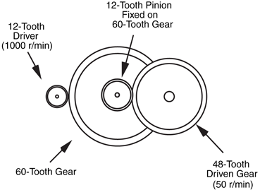
You can reduce the speed of a motor in steps by using the arrangement shown in Fig.
19-8. Here, the driver gear turns a larger hub gear, which in turn has a smaller gear permanently
attached to its shaft. The small hub gear turns the driven gear to produce the final
output speed, in this case 50 r/min. You can repeat this process over and over again until
the output speed is but a tiny fraction of the input speed. This is the arrangement most
often used in motor gear reduction systems.
It's always easiest to use DC motors that already have a gear reduction box built onto them,
such as the motor in Fig. 19-9. R/C servo motors already incorporate gear reduction, as do
most stepper motors. This fact saves you from having to find a gear reducer that fits the
motor and application and attach it yourself. When selecting gear motors, you'll be most
interested in the output speed of the gearbox, not the actual running speed of the motor.
Note as well that the running and stall torque of the motor will be greatly increased. Make
sure that the torque specification on the motor is for the output of the gearbox, not the
motor itself.
With most gear reduction systems, the output shaft is opposite the input shaft (but usually
off center). With other boxes, the output and input are on the same side of the box.
When the shafts are at 90 degrees from one another, the reduction box is said to be a
right-angle drive. If you have the option of choosing, select the kind of gear reduction that
best suits the design of your robot. You will probably find that shafts on opposite sides is
the all-around best choice. Right-angle drives also come in handy, but they usually carry
high price tags.
When using motors without built-in gear reduction, you'll need to add reduction boxes,
such as the model shown in Fig. 19-10, or make your own. Although it is possible to do
both of these yourself, there are many pitfalls:

Figure 19-10 A gear reduction box, originally removed from an open-frame AC motor. On this
unit, the input and output shafts are on the same side.
- Shaft diameters of motors and ready-made gearboxes may differ, so you must be sure that the motor and gearbox mate.
- Separate gear reduction boxes are hard to find. Most must be cannibalized from salvage motors. Old AC motors are one source of surplus boxes.
- When designing your own gear reduction box, you must take care to ensure that all the gears have the same hub size and that meshing gears exactly match each other.
- Machining the gearbox requires precision, since even a small error can cause the gears to mesh improperly.
Gears consist of teeth, but these teeth can come in any number of styles, sizes, and orientations.
Spur gears are the most common type. The teeth surround the outside edge of the
gear, as shown in Fig. 19-11. Spur gears are used when the drive and driven shafts are parallel.
Bevel gears have teeth on the surface of the circle rather than the edge. They are used
to transmit power to perpendicular shafts. Miter gears serve a similar function but are
designed so that no reduction takes place. Spur, bevel, and miter gears are reversible. That
is, unless the gear ratio is very large, you can drive the gears from either end of the gear system,
thus increasing or decreasing the input speed.

Figure 19-11 Spur gears. These particular gears are made of nylon and have aluminum hubs.
It's better to use metal hubs in which the gear is secured to the shaft with a setscrew.
Worm gears transmit power perpendicularly, like bevel and miter gears, but their design
is unique. The worm (or lead screw) resembles a threaded rod. The rod provides the power. As it turns, the threads engage a modified spur gear (the modification takes into consideration
the cylindrical shape of the worm).
Worm gear systems are specifically designed for large-scale reduction. The gearing is not
usually reversible; you can't drive the worm by turning the spur gear. This is an important
point because it gives worm gear systems a kind of automatic locking capability. Worm
gears are particularly well suited for arm mechanisms in which you want the joints to remain
where they are. With a traditional gear system, the arm may droop or sink back due to gravity
once the power from the drive motor is removed.
Rack gears are like spur gears unrolled into a flat rod. They are primarily intended to
transmit rotational motion to linear motion. Racks have a kind of self-locking characteristic
as well, but it's not as strong as that found in worm gears.
The size of gear teeth is expressed as pitch, which is roughly calculated by counting the
number of teeth on the gear and dividing it by the diameter of the gear. For example, a gear
that measures 2 in and has 48 teeth has a tooth pitch of about 24. Common pitches are 12
(large), 24, 32, and 48. Some gears have extra-fine 64-pitch teeth, but these are usually
confined to miniature mechanical systems, such as radio-controlled models. Odd-sized
pitches exist, of course, as do metric sizes, so you must be careful when matching gears that
the pitches are exactly the same. Otherwise, the gears will not mesh properly and may
cause excessive wear.
The degree of slope of the face of each tooth is called the pressure angle. The most common
pressure angle is 20, although some gears, particularly high-quality worms and racks,
have a 14  in pressure angle. Textbooks claim that you should not mix two gears with different
pressure angles even if the pitch is the same, but it can be done. Some excessive wear
may result because the teeth aren't meshing fully.
in pressure angle. Textbooks claim that you should not mix two gears with different
pressure angles even if the pitch is the same, but it can be done. Some excessive wear
may result because the teeth aren't meshing fully.
in pressure angle. Textbooks claim that you should not mix two gears with different
pressure angles even if the pitch is the same, but it can be done. Some excessive wear
may result because the teeth aren't meshing fully.The orientation of the teeth on the gear can differ. The teeth on most spur gears are perpendicular
to the edges of the gear. But the teeth can also be angled, as shown in Fig.
19-12, in which case it is called a helical gear.

Figure 19-12 Standard spur gear versus diagonal helical
spur gear. The latter is used to decrease backlash—the
play inherent when two gears mesh. Some helical gears are
also made for diverting the motion at right angles.
A number of other unusual tooth geometries are in use. These include double-teeth,
where two rows of teeth offset one another, and herringbone, where there are two sets of
helical gears at opposite angles. These gears are designed to reduce the backlash phenomenon.
The space (or play) between the teeth when meshing can cause the gears to rock
back and forth.
Akin to the gear are pulleys, belts, sprockets, and roller chains. Pulleys are used with belts,
and sprockets are used with roller chain. The pulley and sprocket are functionally identical
to the gear. The only difference is that pulleys and sprockets use belts and roller chain,
respectively, to transfer power. With gears, power is transferred directly.
A benefit of using pulleys-belts or sprockets-chain is that you don't need to be as concerned
with the absolute alignment of the mechanical parts of your robot. When using gears
you must mount them with high precision. Accuracies to the hundredths of an inch are
desirable to avoid slop in the gears as well as the inverse—binding caused by gears that are
meshing too tightly. Belts and roller chain are designed to allow for slack; in fact, if there's
no slack you run the risk of breaking the pulley or chain!
Pulleys come in a variety of shapes and sizes. You're probably familiar with the pulleys and
belts used in automotive applications. These are likely to be too bulky and heavy to be used
with a robot. Instead, look for smaller and lighter pulleys and belts used for copiers, fax
machines, VCRs, and other electronic equipment. These are available for salvage from
whole units or in bits and pieces from surplus outlets.
Pulleys can be either the V type (the pulley wheel has a V-shaped groove in it) or the cog
type. Cog pulleys require matching belts. You need to ensure that the belt is not only the
proper width for the pulley you are using but also has the same cog pitch.
Sprockets and roller chain are preferred when you want to ensure synchronism. For large
robots you can use  -in bicycle chain. Most smaller robots will do fine with
  -in roller chain,
which can frequently be found in surplus stores. Metal roller chain is commonly available in
preset lengths, though you can sometimes shorten or lengthen the chain by adding or
removing links. Plastic roller chain, while not as strong, can be adjusted more easily by using
snap-on links.
-in roller chain,
which can frequently be found in surplus stores. Metal roller chain is commonly available in
preset lengths, though you can sometimes shorten or lengthen the chain by adding or
removing links. Plastic roller chain, while not as strong, can be adjusted more easily by using
snap-on links.
-in bicycle chain. Most smaller robots will do fine with -in roller chain,
which can frequently be found in surplus stores. Metal roller chain is commonly available in
preset lengths, though you can sometimes shorten or lengthen the chain by adding or
removing links. Plastic roller chain, while not as strong, can be adjusted more easily by using
snap-on links.
Every motor requires a different mounting arrangement. It's easier for you when the motor
has its own mounting hardware or holes; you can use these to mount the motor in your
robot. Remember that Japanese- and European-made motors often have metric threads, so
be sure to use the proper-sized bolt.
Other motors may not be as cooperative. Either the mounting holes are in a position
where they don't do you much good, or the motor is completely devoid of any means for
securing it to your robot. You can still mount these motors successfully by using an assortment
of clamps, brackets, woodblocks, and homemade angles.
For example, to secure the motor shown in Fig. 19-13, mounting brackets were fashioned
using 6-in galvanized iron mending T plates. A large hole was drilled for the drive
shaft and gear to poke through, and the two halves of the mounting bracket were joined
together with nuts, bolts, and spacers. The bracket was then attached to the frame of the
robot using angle irons and standard hardware. This motor arrangement was made a little
more difficult by the addition of a drive gear and sprocket. Construction time for each motor
bracket was about 90 min.

Figure 19-13 One approach to mounting a large motor in a robot. The motor is sandwiched
inside two large hardware plates and is secured to the frame of the motor with angle irons.
Another example is shown in Fig. 19-14. Here, the motor has mounting holes on the
end by the shaft, but these holes are in the wrong position for the design of the robot.
Two commonly available flat corner irons were used to mount the motor. This is just one
approach; a number of other mounting schemes might have worked satisfactorily as well.
This design is more thoroughly discussed in Chapter 27, "Build a Revolute Coordinate
Arm."

Figure 19-14 Another approach to mounting a motor to a robot. Flat corner irons secure the
motor flange to the frame.
You can also fashion your own mounting brackets using metal or plastic. Cut the bracket
to the size you need, and drill mounting holes. This technique works well when you are
using servo motors for model radio-controlled cars and airplanes.
If the motor lacks mounting holes, you can use clamps to hold it in place. U-bolts, available
at the hardware store, are excellent solutions. Choose a U-bolt that is large enough to
fit around the motor. The rounded shape of the bolt is perfect for motors with round casings.
If desired, you can make a holding block out of plastic or wood to keep the bottom of
the motor from sliding. Cut the plastic or wood to size, and round it out with a router, rasp,
or file so it matches the shape of the motor casing.
Connecting the shaft of the motor to a gear, wheel, lever, or other mechanical part is probably
the most difficult task of all. There is one exception to this, however: R/C servo motors
are easier to mount, which is one reason they are so popular in hobby robotics. Motor
shafts come in many different sizes, and because most—if not all—of the motors you'll use
will come from surplus outlets, the shaft may be peculiar to the specific application for
which the motor was designed.
Common shaft sizes are  - and
- and  -in for small hobby motors and -, -, or
  -in for larger motors and gearboxes. Gear hubs are generally -, -, or
  -in, so you'll need to find
reducing bushings at an industrial supply store. Surplus is also a good source. The same
goes for wheels, sprockets (for roller chain and timing pulleys), and bearings.
-in, so you'll need to find
reducing bushings at an industrial supply store. Surplus is also a good source. The same
goes for wheels, sprockets (for roller chain and timing pulleys), and bearings.
- and -in for small hobby motors and -, -, or -in for larger motors and gearboxes. Gear hubs are generally -, -, or -in, so you'll need to find
reducing bushings at an industrial supply store. Surplus is also a good source. The same
goes for wheels, sprockets (for roller chain and timing pulleys), and bearings.To attach things like gears and sprockets, the gear or sprocket must usually be physically
secured to the shaft by way of a setscrew, as depicted in Fig. 19-15. Sometimes a press fit
is all that's required. Most better-made gears and sprockets have the setscrews in them or
have provisions for inserting them. If the gear or sprocket has no setscrew and there is no
hole for one, you'll have to drill and tap the hole for the screw.

There are two common alternatives if you can't use a setscrew. The first method is to
add a spline, or key, to secure the gear or sprocket to the shaft. This requires some careful
machining, as you must make a slot for the spline in the shaft as well as for the hub of
the gear or sprocket. Another method is to thread the gear shaft, and mount the gear or
sprocket using nuts and split lock washers (the split in the washer provides compression
that keeps the assembly from working loose). Shaft threading is also sometimes necessary
when you are attaching wheels. Many people find that threading the shaft is easier.
Threading requires you to lock the shaft so it won't turn, which can be a problem with
some motors. Also, be careful that the shavings from the threading die do not fall into the
motor.
Attaching two shafts to one another is a common, but not insurmountable, problem.
The best approach is to use a coupler. You tighten the coupler to the shaft using setscrews.
Couplers are available from industrial supply houses and can be expensive, so shop carefully.
Some couplers are flexible; that is, they give if the two shafts aren't perfectly aligned.
These are the best, considering the not-too-close tolerances inherent in home-built robots.
Some couplers are available that accept two shafts of different sizes.
To learn more about . . . |
Read |
|
Robot locomotion systems |
Chapter 18, "Principles of Robot Locomotion" |
|
All about DC motors |
Chapter 20, "Working with DC Motors" |
|
All about stepper motors |
Chapter 21, "Working with Stepper Motors" |
|
All about servo motors |
Chapter 22, "Working with Servo Motors" |
|
Operating motors by computer |
Chapter 12, "An Overview of Robot ‘Brains’" |
|
Interfacing motors to electronic circuitry |
Chapter 14, "Computer Peripherals" |