WORKING WITH
STEPPER MOTORS
STEPPER MOTORS
The past chapters have looked at powering robots using everyday continuous DC
motors. DC motors are cheap, deliver a lot of torque for their size, and are easily adaptable
to a variety of robot designs. By their nature, however, the common DC motors are
rather imprecise. Without a servo feedback mechanism or tachometer, there’s no telling
how fast a DC motor is turning. Furthermore, it’s difficult to command the motor to turn a
specific number of revolutions, let alone a fraction of a revolution. Yet this is exactly the kind
of precision robotics work, particularly arm designs, often requires.
Enter the stepper motor. Stepper motors are, in effect, DC motors with a twist. Instead
of being powered by a continuous flow of current, as with regular DC motors, they are
driven by pulses of electricity. Each pulse drives the shaft of the motor a little bit. The more
pulses that are fed to the motor; the more the shaft turns. As such, stepper motors are
inherently digital devices, a fact that will come in handy when you want to control your
robot by computer. By the way, there are AC stepper motors as well, but they aren’t really
suitable for robotics work and so won’t be discussed here.
Stepper motors aren’t as easy to use as standard DC motors, however, and they’re also
harder to get and more expensive. But for the applications that require them, stepper
motors can solve a lot of problems with a minimum of fuss.
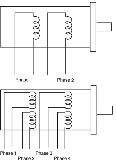
There are several designs of stepper motors. The most popular variety is the four-phase
unipolar stepper, like the one in Fig. 21-1. A unipolar stepper motor is really two motors
sandwiched together, as shown in Fig. 21-2. Each motor is composed of two windings.
Wires connect to each of the four windings of the motor pair, so there are eight wires coming
from the motor. The commons from the windings are often ganged together, which
reduces the wire count to five or six instead of eight (see Fig. 21-3).
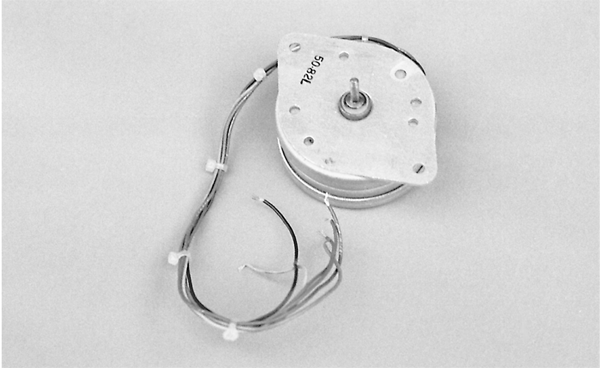
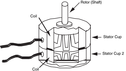
Figure 21-2 Inside a unipolar stepper motor. Note the two sets of coils and
stators. The unipolar stepper is really two motors sandwiched together.
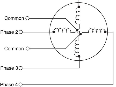
Figure 21-3 The wiring diagram of the unipolar stepper. The common
connections can be separate or combined.
In operation, the common wires of a unipolar stepper are attached to the positive
(sometimes the negative) side of the power supply. Each winding is then energized in
turn by grounding it to the power supply for a short time. The motor shaft turns a fraction
of a revolution each time a winding is energized. For the shaft to turn properly, the
windings must be energized in sequence. For example, energize wires 1, 2, 3, and 4 in
sequence and the motor turns clockwise. Reverse the sequence, and the motor turns the
other way.
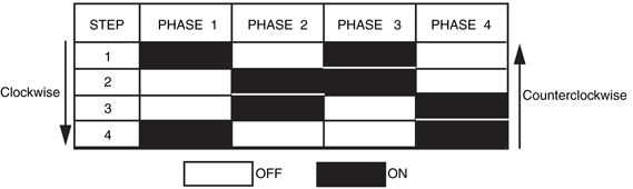
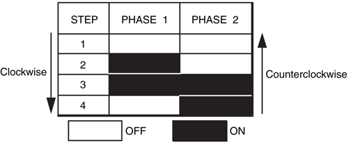
The wave step sequence is the basic actuation technique of unipolar stepper motors.
Another, and far better, approach actuates two windings at once in an on-on/off-off four-step sequence, as shown in Fig. 21-4. This enhanced actuation sequence increases the
driving power of the motor and provides greater shaft rotation precision.
There are other varieties of stepper motors, and they are actuated in different ways. One
you may encounter is bipolar. It has four wires and is pulsed by reversing the polarity of the
power supply for each of the four steps. The actuation technique for these motors will be
discussed later in this chapter.
Stepping motors differ in their design characteristics compared with continuous DC motors.
The following section discusses the most important design specifications for stepper
motors.
A unipolar stepper requires that a sequence of four pulses be applied to its various windings
for it to rotate properly. By their nature, all stepper motors are at least two-phase. Many are
four-phase; some are six-phase. Usually, but not always, the more phases in a motor, the
more accurate it is.
Stepper motors vary in the amount of rotation of the shaft each time a winding is energized.
The amount of rotation is called the step angle and can vary from as small as 0.9° (1.8°
is more common) to 90°. The step angle determines the number of steps per revolution. A
stepper with a 1.8° step angle, for example, must be pulsed 200 times for the shaft to turn
one complete revolution. A stepper with a 7.5° step angle must be pulsed 48 times for one
revolution, and so on.
Obviously, the smaller the step angle is, the more accurate the motor. But the number of
pulses stepper motors can accept per second has an upper limit. Heavy-duty steppers usually
have a maximum pulse rate (or step rate) of 200 or 300 steps per second, so they have
an effective top speed of 1 to 3 r/s (60 to 180 r/min). Some smaller steppers can accept a
thousand or more pulses per second, but they don’t usually provide very much torque and
aren’t suitable as driving or steering motors.
Note that stepper motors can’t be motivated to run at their top speeds immediately from
a dead stop. Applying too many pulses right off the bat simply causes the motor to freeze
up. To achieve top speeds, you must gradually accelerate the motor. The acceleration can
be quite swift in human terms. The speed can be one-third for the first few milliseconds,
two-thirds for the next few milliseconds, then full blast after that.
Steppers can’t deliver as much running torque as standard DC motors of the same size and
weight. A typical 12-V, medium-sized stepper motor may have a running torque of only
25 oz-in. The same 12-V, medium-sized standard DC motor may have a running torque
that is three or four times more.
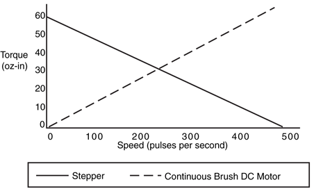
However, steppers are at their best when they are turning slowly. With the typical stepper,
the slower the motor revolves, the higher the torque. The reverse is usually true of continuous
DC motors. Fig. 21-5 shows a graph of the running torque of a medium-duty,
unipolar 12-V stepper. This unit has a top running speed of 550 pulses per second. Since
the motor has a step angle of 1.8°, that results in a top speed of 2.75 r/s (165 r/min).
Actuating one of the windings in a stepper motor advances the shaft. If you continue to
apply current to the winding, the motor won’t turn anymore. In fact, the shaft will be
locked, as if you’ve applied brakes. As a result of this interesting locking effect, you never
need to add a braking circuit to a stepper motor because it has its own brakes built in.
The amount of braking power a stepper motor has is expressed as holding torque. Small
stepper motors have a holding torque of a few oz-in. Larger, heavier-duty models have holding
torques exceeding 400 oz-in.
Like DC motors, stepper motors vary in their voltage and current ratings. Steppers for 5-,
6-, and 12-V operation are not uncommon. But unlike DC motors, if you use a higher voltage
than specified for a stepper motor you don’t gain faster operation but more running
and holding torque. Overpowering a stepper by more than 80 to 100 percent above the
rated voltage may eventually burn up the motor.
The current rating of a stepper is expressed in amps (or milliamps) per phase. The power
supply driving the motor needs to deliver at least as much as the per-phase specification,
preferably more if the motor is driving a heavy load. The four-step actuation sequence powers
two phases at a time, which means the power supply must deliver at least twice as much
current as the per-phase specification. If, for example, the current per phase is 0.25 A, the
power requirement at any one time is 0.50 A.
Steppers have been around for a long time. In the old days, stepper motors were actuated
by a mechanical switch, a solenoid-driven device that pulsed each of the windings of the
motor in the proper sequence. Now, stepper motors are invariably controlled by electronic
means. Basic actuation can be accomplished via computer control by pulsing each of the
four windings in turn. The computer can’t directly power the motor, so transistors must be
added to each winding, as shown in Fig. 21-6.
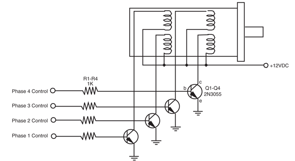
Figure 21-6 The basic hookup connection to drive a stepper motor from a computer or other electronic
interface. The phasing sequence is provided by software or other means through a port following a four-bit
binary sequence: 1010, 0110, 0101, 1001 (reverse the sequence to reverse the motor).
In the absence of direct computer control, the easiest way to provide the proper sequence
of actuation pulses is to use a custom stepper motor chip, such as the Allegro Microsystems
UCN5804. This chip is designed expressly for use with the common unipolar stepper
motor and provides a four-step actuation sequence. Stepper motor translator chips tend to
be modestly priced, at about $5 to $10, depending on their features and where you buy
them.
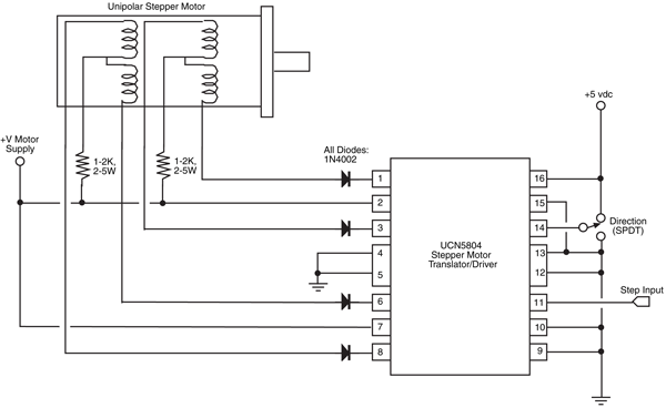
Fig. 21-7 (refer to the parts list in Table 21-1) shows a typical schematic of the
UCN5804. Heavier-duty motors (more than about 1 A per phase) can be driven by adding
power transistors to the four outputs of the chips, as shown in the manufacturer’s application
notes. Note the direction pin. Pulling this pin high or low reverses the rotation of the
motor.
IC1 |
Allegro UCN5804 Stepper Motor Translator IC |
R1, R2 |
1–2K resistor, 2–5 watts |
D1–D4 |
1N4002 diode |
M1 |
Unipolar stepper motor |
Misc. |
SPDT switch, heat sinks for UCN5804 (as needed) |
Another approach to operating unipolar stepper motors is to use discrete gates and clock
ICs. You can assemble a stepper motor translator circuit using just two IC packages. The circuit
can be constructed using TTL or CMOS chips.
The TTL version is shown in Fig. 21-8 (refer to the parts list in Table 21-2). Four exclusive
OR gates from a single 7486 IC provide the steering logic. You set the direction by
pulling pin 12 HIGH or LOW. The stepping actuation is controlled by a 7476, which contains
two JK flip-flops. The Q and  outputs of the flip-flops control the phasing of the
motor. Stepping is accomplished by triggering the clock inputs of both flip-flops.
outputs of the flip-flops control the phasing of the
motor. Stepping is accomplished by triggering the clock inputs of both flip-flops.
outputs of the flip-flops control the phasing of the
motor. Stepping is accomplished by triggering the clock inputs of both flip-flops.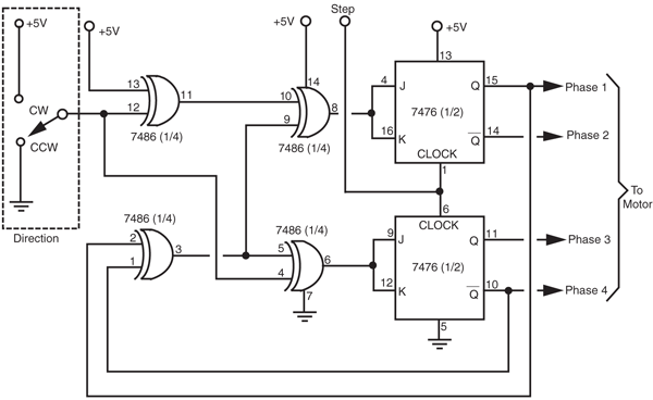
Figure 21-8 Using a pair of commonly available TTL ICs to construct your own stepper motor
translator circuit.
IC1 |
7485 Quad Exclusive OR Gate IC |
IC2 |
7476 Dual “JK” flip-flop IC |
The 7476 can’t directly power a stepper motor. You must use power transistors or
MOSFETs to drive the windings of the motor. See the section titled “Translator Enhancements”
for a complete power driving schematic as well as other options you can add to this
circuit.
The CMOS version, shown in Fig. 21-9 (refer to the parts list in Table 21-3), is identical
to the TTL version, except that a 4070 chip is used for the exclusive OR gates and a 4027
is used for the flip-flops. The pinouts are slightly different, so follow the correct schematic
for the type of chips you use. Note that another CMOS exclusive OR package, the 4030,
is also available. Don’t use this chip; it behaves erratically in this, as well as other pulsed, circuits.
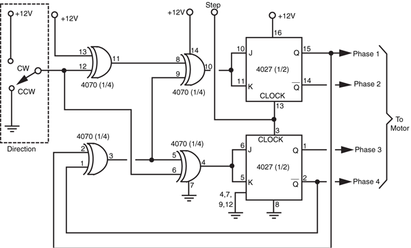
Figure 21-9 Using a pair of commonly available CMOS ICs to construct your own stepper
motor translator circuit.
IC1 |
4070 Quad Exclusive OR Gate IC |
IC2 |
4027 Dual “JK” flip-flop IC |
In both the TTL and CMOS circuits, the stepper motor itself can be operated from a supply
voltage that is wholly different from the voltage supplied to the ICs. It should be pointed
out that stepper motor translator circuits are excellent first microcontroller applications.
Along with providing an intelligent approach to controlling stepper motors, small microcontrollers
can cost as little as $0.50—probably less than the cost of one chip used in the
circuits shown in Fig. 21-8 and 21-9 and much easier to wire into a circuit.
Four NPN power transistors, four resistors, and a handful of diodes are all the translator circuits
described in the last section need to provide driving power. (You can also use this
scheme to increase the driving power of the UCN5804, detailed earlier.) The schematic for
the circuit is shown in Fig. 21-10 (refer to the parts list in Table 21-4). Note that you can
substitute the bipolar transistors and resistors with power MOSFETs. See Chapter 19,
“Choosing the Right Motor,” for more information on using power MOSFETs.
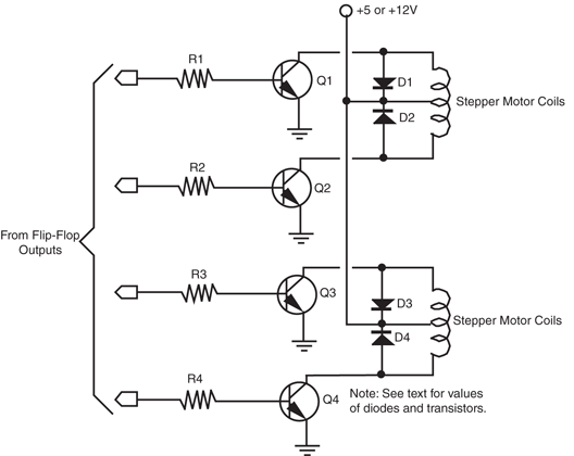
Figure 21-10 Add four transistors and resistors to provide a power output stage for
the TTL or CMOS stepper motor translator circuits.
Q1–Q4 |
Under 1 A draw per phase: TIP32 NPN transistor 1 to 3 A draw per
phase: TIP120 NPN Darlington transistor |
R1–R4 |
1K resistor, 1 W |
D1–D4 |
1N4004 diode |
Misc. |
Heat sinks for transistors |
You can use just about any NPN power transistor that will handle the motor. The TIP31
is a good choice for applications that require up to 1 A of current. Use the 2N3055 for
heavier-duty motors. Mount the drive transistors on a suitable heat sink.
You must insert a bias resistor in series between the outputs of the translation circuit and
the base of the transistors. Values between about 1K and 3K should work with most motors
and most transistors. Experiment until you find the value that works without causing the flip-flop
chips to overheat. You can also apply Ohm’s law, figuring in the current draw of the
motor and the gain of the transistor, to accurately find the correct value of the resistor. If this
is new to you, see Appendix A, “Further Reading,” for a list of books on electronic design
and theory.
It is sometimes helpful to see a visual representation of the stepping sequence. Adding
an LED and current-limiting resistor in parallel with the outputs provides just such a visual
indication. See Fig. 21-11 for a wiring diagram (refer to the parts list in Table 21-5). Note
the special wiring to the flip-flop outputs. This provides a better visual indication of the stepping
action than hooking up the LEDs in the same order as the motor phases.
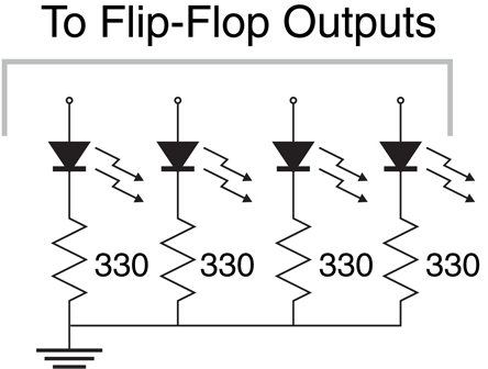
R1–R4 |
330 Ω resistors |
LED1–4 |
Visible light LEDs |
Fig. 21-12 shows two stepper motor translator boards. The small board controls up to
two stepper motors and is designed using TTL chips. The LED option is used to provide a
visual reference of the step sequence. The large board uses CMOS chips and can accommodate
up to four motors. The boards were wire-wrapped; the driving transistors are
placed on a separate board and heat sink.
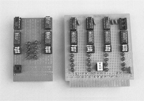
Figure 21-12 Two finished stepper motor translator boards, with indicator LEDs. The board on
the left controls two stepper motors; the board on the right controls four stepper motors.
You need a square wave generator to provide the triggering pulses for the motors. You can
use the 555 timer wired as an astable multivibrator, or make use of a control line in your computer or microcontroller. When using the 555, remember to add the 0.1 μF capacitor
across the power pins of the chip. The 555 puts a lot of noise into the power supply, and
this noise regularly disturbs the counting logic in the exclusive OR and flip-flop chips. If you
are getting erratic results from your circuit, this is probably the cause.
As detailed earlier in the chapter, unipolar stepper motors contain four coils in which two of
the coils are joined to make a center tap. This center tap is the common connection for the
motor. Bipolar stepper motors contain two coils, do not use a common connection, and are
generally less expensive because they are easier to manufacture. A bipolar stepper motor has
four external connection points. An old method for operating a bipolar stepper motor was
to use relays to reverse the polarity of a DC voltage to two coils. This caused the motor to
inch forward or backward, depending on the phasing sequence.
Today, the more common method for operating a bipolar stepper motor is to use a specialty
stepper motor translator, such as the SGS-Thompson L297D (the L297D can also be
used to drive unipolar stepper motors). To add more current driving capacity to the L297D you can add a dual H-bridge driver, such as the L298N, which is available from the same
company. The truth table for the typical driving sequence of a bipolar stepper motor is
shown in Fig. 21-13.
Spend some time with a stepper motor and you'll invariably come to admire its design and
be able to think up all sorts of ways to make it work for you in your robot designs. But to
use a stepper, you have to get one. That in itself is not always easy. Then after you have
obtained it and taken it home, there’s the question of figuring out where all the wires go!
Let’s take each problem one at a time.
Despite their many advantages, stepper motors aren't nearly as common as the trusty DC
motor, so they are harder to find. And when you do find them, they're expensive when
new. The surplus market is by far the best source for stepper motors for hobby robotics. See
Appendix B, "Sources," for a list of selected mail-order surplus companies that regularly
carry a variety of stepper motors. They carry most of the name brand steppers: Thompson-Airpax, Molon, Haydon, and Superior Electric. The cost of surplus steppers is often a quarter
or fifth of the original list price.
The disadvantage of buying surplus is that you don’t always get a hookup diagram or
adequate specifications. Purchasing surplus stepper motors is largely a hit-or-miss affair, but
most outlets let you return the goods if they aren’t what you need. If you like the motor, yet
it still lacks a hookup diagram, read the following section on how to decode the wiring.
The internal wiring diagram of both a bipolar and unipolar stepper motor is shown in Fig.
21-14. The wiring in a bipolar stepper is actually easy to decode. A DMM is used to measure
the resistance between wire pairs. You can be fairly sure the motor is two-phase if it
has only four wires leading to it. You can identify the phases by connecting the leads of the
meter to each wire and noting the resistance. Wire pairs that give an open reading (infinite
ohms) represent two different coils (phases). You can readily identify mating phases when
there is a small resistance through the wire pair.
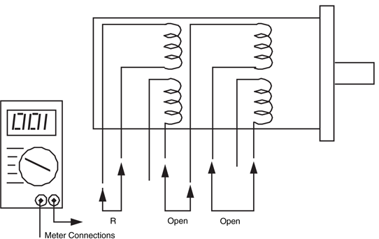
Unipolar steppers behave the same, but with a slight twist. Let’s say, for argument’s
sake, that the motor has eight wires leading to it. Each winding, then, has a pair of wires.
Connect your meter to each wire in turn to identify the mating pairs. As illustrated in Fig.
21-15, no reading (infinite ohms) signifies that the wires do not lead to the same winding;
a reading indicates a winding.
If the motor has six wires, then four of the leads go to one side of the windings. The
other two are commons and connect to the other side of the windings (see Fig. 21-16).
Decoding this wiring scheme takes some patience, but it can be done. First, separate all those wires where you get an open reading. At the end of your test, there should be two
three-wire sets that provide some reading among each of the leads.
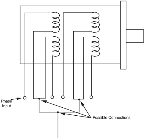
Figure 21-16 Common connections may reduce the wire count of the stepper
motor to five or six, instead of eight.
Locate the common wire by following these steps. Take a measurement of each combination
of the wires and note the results. You should end up with three measurements: wires
1 and 2, wires 2 and 3, and wires 1 and 3. The meter readings will be the same for two of
the sets. For the third set, the resistance should be roughly doubled. These two wires are the
main windings. The remaining wire is the common.
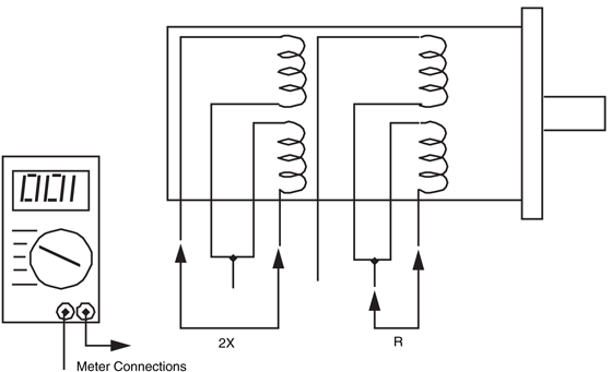
Decoding a five-wire motor is the most straightforward procedure. Measure each wire
combination, noting the results of each. When you test the leads to one winding, the result
will be a specified resistance (let’s call it "R"). When you test the leads to two of the windings,
the resistance will be double the value of "R," as shown in Fig. 21-17. Isolate this common
wire with further testing and you’ve successfully decoded the wiring.
To learn more about . . . |
Read |
|
Driving a robot |
Chapter 18, "Principles of Robot Locomotion" |
|
Selecting a motor for your robot |
Chapter 19, "Choosing the Right Motor" |
|
Connecting motors to computers, microcontrollers, and other electronic circuitry |
Chapter 14,"Computer Peripherals" |