Chapter 14
Attaching Holograms to Real Objects with Vuforia
Vuforia is an augmented reality platform that you can use to supplement your HoloLens and mobile apps with robust AR experiences. Vuforia uses computer vision algorithms that recognize and track real objects that you select. Vuforia can track various objects, which Vuforia calls targets, including images, 3D models, and something referred to as VuMarks, which can be understood as colorful two-dimensional barcodes. For UWP apps running on a Surface, Vuforia can also be used to detect ground planes.
When Vuforia recognizes a target, it can automatically attach digital content that you specify to it, essentially augmenting it with virtually generated objects that move with it. Vuforia is great for developing mixed reality (MR) apps in which digital content should be connected with real objects—for example, to provide instructions or to associate a real object with a hologram. Unity version 2017.2 and beyond include Vuforia 7, so you can start using Vuforia capabilities in your HoloLens apps straight away.
![]() Note
Note
The Vuforia website features plenty of mobile apps. However, there are not so many examples of HoloLens apps. This leaves you plenty of room to let your imagination run wild!
This chapter shows you how to use Vuforia to attach digital content to a target. When you complete this chapter, you will end up with an app that recognizes a specific image and displays the Ethan character on top of it. The Ethan character will also walk between the two opposite vertices of the recognized image to produce the illusion that the digitally created character is walking on the real surface. (See Figure 14-1.) To create this app, I displayed the X sign on my smartphone. Apart from relatively low image quality, Vuforia correctly recognized the object and attached the Ethan hologram to it. Ethan’s position changes when I move my smartphone due to robust tracking provided by Vuforia.

Creating the Project and Adding the AR Camera Prefab
Your first step is to create the Unity project for the app. Follow these instructions:
- Create a new 3D Unity project and name it HoloAugmentedExperience.
- Import the Mixed Reality Toolkit for Unity.
- Apply the default Mixed Reality project and scene settings. (Refer to Chapters 12 and 13 for guidance.)
- Open the Mixed Reality Toolkit menu, choose Configure, and select Apply UWP Capability Settings to open the Apply UWP Capability Settings window.
- Select the Webcam, Spatial Perception, and Internet Client checkboxes in the Apply UWP Capability Settings window. Then click the Apply button.
The HoloLens project is configured with default MR settings. Your next step is to extend it to support Vuforia capabilities. To that end, you need to add at least two Vuforia prefabs:
- AR Camera Vuforia uses this prefab to recognize and track targets.
- Image This is the image target—a flat two-dimensional object that Vuforia will look for in the real environment.
To add the AR Camera prefab, follow these steps:
- In the Hierarchy, click Create, choose Vuforia, and select AR Camera. (See Figure 14-2.)
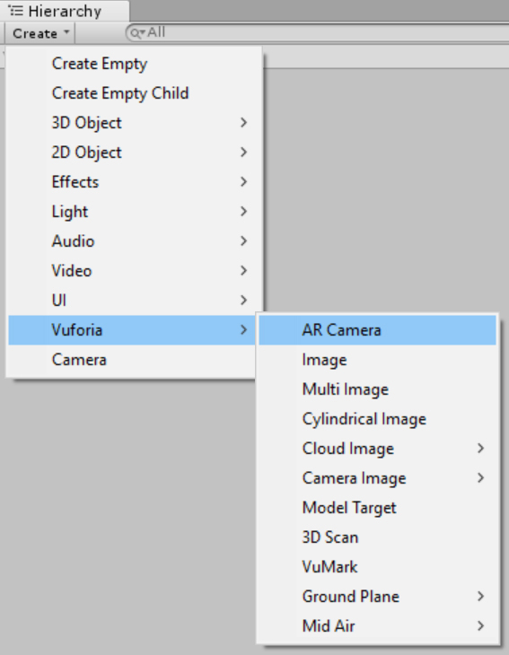
FIGURE 14-2 Adding the AR Camera Vuforia prefab. - The Import Vuforia Assets window opens. (See Figure 14-3.) Click Import to import the prefab. The import operation may take a short while. When it’s finished, you’ll see a new object in the Hierarchy: ARCamera.
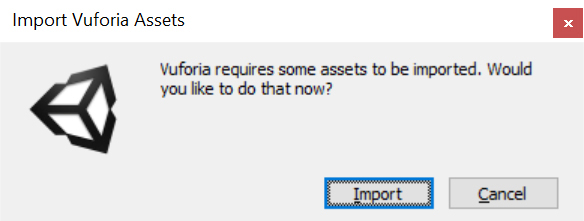
FIGURE 14-3 Importing Vuforia Assets
Click the ARCamera object in the Hierarchy to investigate its properties in the relevant Inspector. As shown in Figure 14-4, the ARCamera prefab has the familiar Transform, Camera, and Audio Listener components. For now, deselect the Audio Listener checkbox. This is to avoid conflicts with the listener from the MixedRealityCamera object. If you have both listeners enabled, Unity will display the following error in the console:
“There are 2 audio listeners in the scene. Please ensure there is always exactly one audio listener in the scene.”
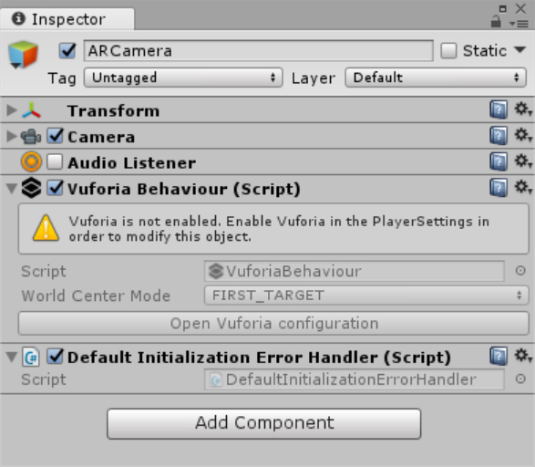
Notice that ARCamera has two scripts attached:
- Vuforia Behaviour This script implements the base class for all objects delivered by Vuforia.
- Default Initialization Error Handler This script implements a default logic for handling Vuforia initialization errors.
As shown in Figure 14-4, properties of Vuforia behavior are inactive. This is because Vuforia is currently disabled. To enable Vuforia, you must configure PlayerSettings. Follow these steps:
- Open the File menu and choose Build Settings or press Ctrl+Shift+B to open the Build Settings window.
- Click Player Settings.
- In the Inspector, scroll down to XR Settings, and select the Vuforia Augmented Reality checkbox. (See Figure 14-5.)
The AR Camera prefab is ready. Next, let’s learn how to use the Image prefab to add the image target.

![]() Note
Note
Because you used Mixed Reality Toolkit for Unity to configure the project, the platform is already set to UWP. Similarly, the scripting backend is set to .NET.
Adding the Image Prefab for the Image Target
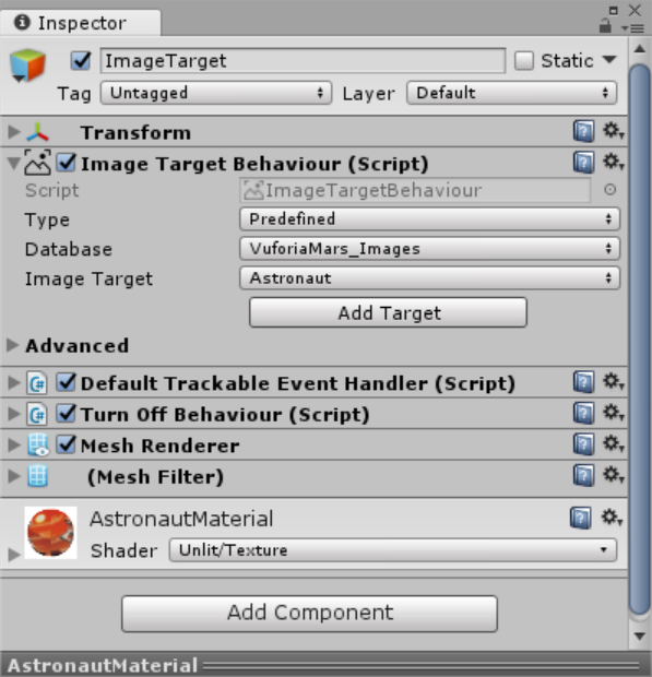
You add the Image prefab the same way you did the AR Camera prefab: In the Hierarchy, click Create, choose Vuforia, and select Image. (Refer Figure 14-2.) A new object appears in the Hierarchy: ImageTarget. Click this object to investigate its properties using the Inspector. (See Figure 14-6.) For now, leave all options at their default values. By default, image target is a picture of an astronaut.
Adding a Hologram to the Target
The Vuforia engine will try to recognize and track the image target you just created. You can go even further and display a hologram whenever the target is recognized. In this section, you will attach the Ethan character to the astronaut image. Follow these steps:
- In the Unity Editor, open the Assets menu, choose Import Package, and select Characters.
- The Import Unity Package window appears. Select All. Then click Import.
- In the Project window, type Ethan t:Model in the search box.
- Drag the Ethan model onto the ImageTarget object in the Hierarchy. The Ethan model will become a child of the ImageTarget object.
- Click Ethan in the Hierarchy. Then, in the Transform group of the Ethan Inspector, configure the X, Y, and Z Position settings to 0.0, 0.1, and –0.3, respectively.
- Set the X, Y, and Z Rotation settings to –90, 0, and 180, respectively.
- Set the X, Y, and Z Scale settings to 0.5, 0.5, and 0.5, respectively. Your scene should look as shown in Figure 14-7.

FIGURE 14-7 The Ethan model lying on top of the astronaut image target.
Testing the App
To test the app, you need some way to place the image target in the real world. There are a couple of ways to do this:
- Create a printout of the image Vuforia provides printable versions of its default image targets, including the astronaut image we’re using here. You can print out this image and hold it up in front of your web camera. The image is available here: Assets\Editor\Vuforia\ForPrint\ImageTargets.
- Display the image on your smartphone Vuforia provides textures, which are stored as JPEG files, for each image target. You can import the texture for the astronaut image target to your smartphone and then hold the smartphone in front of your web camera. The texture is available here: Assets\Editor\Vuforia\ImageTargetTextures\VuforiaMars_Images.
Once you have the image target ready, follow these steps:
- Click the Play button to enable the editor Play mode. Unity will run the app in the Mixed Reality simulator and in the Game view. (I used the Game view.)
- Hold up the image (either the printout or your smartphone) in front of the camera. Vuforia will recognize the target and display the Ethan character on top of it. (See Figure 14-8.)
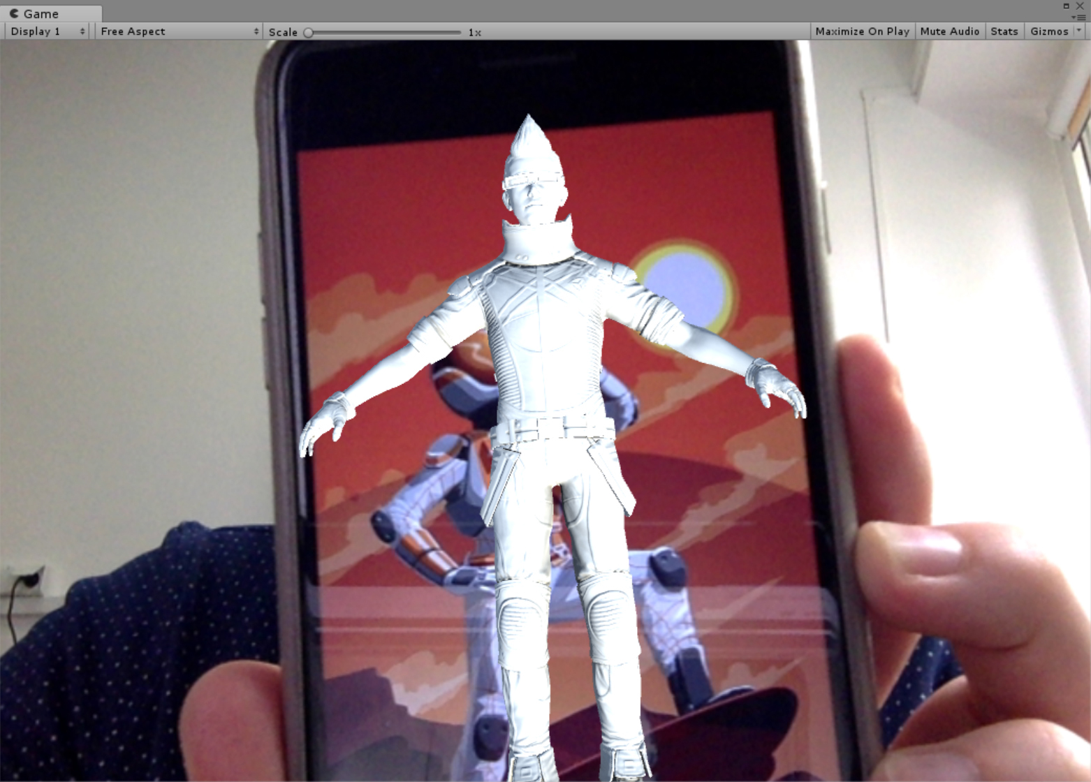
FIGURE 14-8 Attaching a hologram to the image target. - Move the image around in front of the webcam. The Ethan character follows the target as long as the target can be seen by the camera. Notice that Vuforia recognizes and tracks the image target even if you rotate the image or move it closer or further away.
Adding a Text Description
In practical applications, you will most likely supplement the real object with digital content that provides textual instructions or some description of the detected object. To add text, you can use the 3DTextPrefab from the MRTKu package. Let’s see how this works:
- In the Project window, type 3DTextPrefab in the search box.
- Drag the 3DTextPrefab entry in the search results below the ImageTarget object.
- Open the 3DTextPrefab Inspector and type Description in the Name field to rename it.
- In the Transform group of the Inspector, configure the X, Y, and Z Position settings to 0.5, 0, and 0, respectively.
- Set the X, Y, and Z Rotation settings to 90, 0, and 0, respectively.
- In the Text Mesh group, change the Text setting to Target Detected, the Font Size setting to 90, and the Color to Red.
- Run the app and hold the image target in front of the webcam. Text that reads “Target detected” will appear when the app recognizes the image target.
Implementing Extended Tracking
Vuforia automatically displays the selected hologram when the target is recognized. However, the digital content disappears when the image target moves out of the camera field of vision (FOV). Such behavior is not desirable when you want to display larger holograms. You don’t want the hologram to disappear as the user gazes around the scene. Instead, you would like to let the user see the whole hologram. This is where extended tracking comes in. With extended tracking, Vuforia extrapolates the target position based on its past trajectory as shown here: http://bit.ly/extended_tracking.
The best way to visualize this effect is to use an example. Follow these steps:
- Open the Ethan Inspector and, in the Transform group, change the X, Y, and Z Scale settings to 2.
- Open the ImageTarget Inspector, expand the Advanced option in the Image Target Behaviour group (refer to Figure 14-6), and select the Extended Tracking checkbox to enable this feature.
- Click Play button in Unity Editor.
- Hold the image target in the camera’s FOV. The Ethan hologram should be displayed over the image target.
- Move the image target out of the camera’s FOV. Although the image target is no longer visible, Vuforia uses extended tracking to determine Ethan’s location.
Implementing Augmented Navigation
This section shows you how to extend the HoloAugmentedExperience app so that Ethan will walk on the target recognized by Vuforia. (See Figure 14-9.) In Chapter 11, you learned how to implement natural character movement using a navigation mesh. Here, you will use the EthanAnimatorController you developed in that chapter to configure Ethan to switch between idle and walking states.

Using the DefaultTrackableEventHandler Script
In the app, Ethan will walk on the target whenever the target it is actively tracked. To achieve this, you need to know when Vuforia recognizes the target. You can obtain this information from the DefaultTrackableEventHandler script. This script is automatically attached to every image target, which you can quickly verify in the ImageTarget Inspector.
As shown in Listing 14-1, the DefaultTrackableEventHandler class, like any other C# script, derives from the UnityEngine.MonoBehaviour class. The script implements the Vuforia.ITrackableEventHandler interface, which declares the OnTrackableStateChanged method. This method is invoked when the tracking state changes. The object being tracked (here, the image target) is represented by an instance of the Vuforia.ImageTargetBehaviour class. This class derives from Vuforia.DataSetTrackableBehaviour and then from Vuforia.TrackableBehaviour. DefaultTrackableEventHandler stores a reference to the image target in an mTrackableBehaviour field of type TrackableBehaviour. An instance of this type is achieved using the GetComponent generic method. (See the Start method in Listing 14-1.) After that, the current instance of DefaultTrackableEventHandler is registered as a handler that tracks state changes of the image target. (See the last statement of the Start method in Listing 14-1.) In practice, this means that whenever the tracking state changes, OnTrackableStateChanged will be invoked.
LISTING 14-1 Default definition of DefaultTrackableEventHandler
public class DefaultTrackableEventHandler : MonoBehaviour, ITrackableEventHandler
{
protected TrackableBehaviour mTrackableBehaviour;
protected virtual void Start()
{
mTrackableBehaviour = GetComponent<TrackableBehaviour>();
if (mTrackableBehaviour)
mTrackableBehaviour.RegisterTrackableEventHandler(this);
}
// Definition of the OnTrackableStateChanged
// Definitions of the OnTrackingFound and OnTrackingLost methods
}
Listing 14-2 shows the default definition of the OnTrackableStateChanged method.
LISTING 14-2 Handling tracking state changes
public void OnTrackableStateChanged(
TrackableBehaviour.Status previousStatus,
TrackableBehaviour.Status newStatus)
{
if (newStatus == TrackableBehaviour.Status.DETECTED ||
newStatus == TrackableBehaviour.Status.TRACKED ||
newStatus == TrackableBehaviour.Status.EXTENDED_TRACKED)
{
Debug.Log("Trackable " + mTrackableBehaviour.TrackableName + " found");
OnTrackingFound();
}
else if (previousStatus == TrackableBehaviour.Status.TRACKED &&
newStatus == TrackableBehaviour.Status.NOT_FOUND)
{
Debug.Log("Trackable " + mTrackableBehaviour.TrackableName + " lost");
OnTrackingLost();
}
else
{
OnTrackingLost();
}
}
As shown in Listing 14-2, this method supports two arguments, previousStatus and newStatus. Both arguments are of type Vuforia.TrackableBehaviour.Status, which is an enumeration that defines the following values:
- NOT_FOUND This indicates that the target has not been found.
- UNKNOWN This specifies that the tracking state is unknown.
- UNDEFINED This indicates that the tracking state is undefined.
- DETECTED This informs you that the target has been detected.
- TRACKED This indicates that the target is being tracked.
- EXTENDED_TRACKED This specifies that the target is under an extended tracking.
- DEGRADED This indicates that the tracking quality has degraded.
The OnTrackableStateChanged method uses an if clause to check whether newStatus equals DETECTED, TRACKED, or EXTENDED_TRACKED. If so, the method executes two statements. The first statement uses the Debug.Log method to display a string in the console with information about the detected target. (It uses the TrackableName property of the TrackableBehaviour class instance to obtain the name of the target.) The second statement invokes the OnTrackingFound method (discussed later). If newStatus does not equal DETECTED, TRACKED, or EXTENDED_TRACKED, the OnTrackableStateChanged method uses another if clause to determine whether the previousStatus was TRACKED and the newStatus is NOT_FOUND. When this condition is true, the OnTrackableStateChanged method outputs a debug string that indicates which target tracking has been lost. Again, the target’s name is obtained from the TrackableName property. If none of the aforementioned conditions is true, the OnTrackingLost method will be called. (See the statement under the else clause in Listing 14-2.)
Listing 14-3 presents definitions of the OnTrackingFound and OnTrackingLost methods. These methods work in a similar manner. First, they obtain lists of child renderers, colliders, and canvases with respect to the target. Then, the OnTrackingFound method sets the enabled property of each element to true, while the OnTrackingLost method sets the enabled property to false. As a result, OnTrackingFound will show all child holograms of the target, while OnTrackingLost will hide them. Vuforia is no longer able to track the target.
LISTING 14-3 Showing and hiding holograms when the tracking state changes
protected virtual void OnTrackingFound()
{
var rendererComponents = GetComponentsInChildren<Renderer>(true);
var colliderComponents = GetComponentsInChildren<Collider>(true);
var canvasComponents = GetComponentsInChildren<Canvas>(true);
foreach (var component in rendererComponents)
component.enabled = true;
foreach (var component in colliderComponents)
component.enabled = true;
foreach (var component in canvasComponents)
component.enabled = true;
}
protected virtual void OnTrackingLost()
{
var rendererComponents = GetComponentsInChildren<Renderer>(true);
var colliderComponents = GetComponentsInChildren<Collider>(true);
var canvasComponents = GetComponentsInChildren<Canvas>(true);
foreach (var component in rendererComponents)
component.enabled = false;
foreach (var component in colliderComponents)
component.enabled = false;
foreach (var component in canvasComponents)
component.enabled = false;
}
These definitions are the defaults. You can freely adjust them to your needs. Later in this chapter you will use OnTrackingFound and OnTrackingLost to invoke statements that will send a message to another script that will make Ethan walk. Before doing that, however, let’s prepare the scene.
Preparing the Scene
To prepare the scene, start by modifying Ethan’s properties. Follow these steps:
- In the Ethan Inspector, in the Transform group, change the X, Y, and Z Position settings to 0.
- Change the X, Y, and Z Rotation settings to 0.
- Change the X, Y, and Z Scale settings to 0.2, 0.2, and 0.2, respectively.
- In the Project window, create a new folder called Animations inside the Assets folder.
- Right-click the Animations folder and choose Import New Asset from the menu that appears.
- In the Import New Asset window, import the EthanAnimatorController.controller file you created in Chapter 11. (You can find this file with the companion code in the following folder: Chapter_11\AnimatedHumanoid\Assets\Animations.)
- Drag the EthanAnimatorController object that appears in the Hierarchy onto the Ethan model in the scene.
- In the Ethan Inspector, click Add Component, choose Navigation, and select Nav Mesh Agent.
- In the Project window, create a new folder called Scripts in the Assets folder.
- Right-click the Scripts folder, choose Create, and select C# Script. Name the new script Patrolling.
- Drag the Patrolling script onto the Ethan model in the scene.
Now that you’ve configured Ethan, you’re ready to create two new objects: the plane used to define the navigation mesh and an empty object with a LineRenderer component. The LineRenderer component will draw a line connecting Ethan’s current position with the position he is moving toward.
To create the navigation mesh, proceed as follows:
- In the Hierarchy, right-click the ImageTarget object, choose 3D Object, and select Plane to add a Plane object to the scene.
- In the Plane Inspector, change the name of the Plane object to ReferencePlane.
- Open the Window menu and choose Navigation to open the Navigation window.
- Select the ReferencePlane object in the Hierarchy. Then, in the Navigation window, click the Object tab.
- Select the Navigation Static checkbox in the Object tab.
- Open the Navigation Area drop-down list and choose Walkable.
- Click the Bake tab in the Navigation window. Then click the Bake button to construct the navigation mesh. (This could take a moment.)
 Tip
TipIf you do not see the navigation mesh, enlarge the ReferencePlane object—for example, change the X and Z Scale settings in the Transform group in the ReferencePlane Inspector to 10. Then re-bake the navigation mesh.
- In the ReferencePlane Inspector, change the X, Y, and Z Scale settings in the Transform group to 0.055, 1, and 0.1, respectively.
The walkable area is already defined. However, there is no need to render this plane when the target is displayed. The plane is used only to define the walkable area, and to easily find points that will be used to set destinations for patrolling. To easily hide the ReferencePlane object, you can use the transparent_background material from the MRTKu. Follow these steps:
- In the Project window, type transparent t:Material in the search box.
- Drag the transparent_background.mat entry in the search results onto the ReferencePlane object in the scene.
- In the ReferencePlane Inspector, in the transparent_background group, open the Cull Mode drop-down list and choose Front. (See Figure 14-10.) The ReferencePlane will now be enabled when the image target is recognized but will remain invisible.
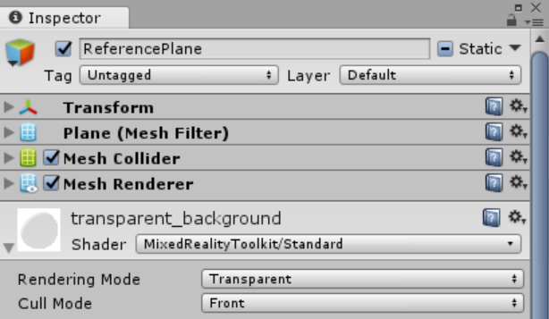
FIGURE 14-10 Configuring the transparent background shader.
Next, you will create the object that will indicate the path Ethan will follow when walking, which I will call the TargetIndicator. You will design this object using an empty GameObject object with a LineRenderer component. This component draws a straight line between two or more points. To create the TargetIndicator, follow these steps:
- In the Hierarchy, right-click the ImageTarget object and choose Create Empty.
- Name the new object TargetIndicator.
- Open the Inspector for the TargetIndicator object.
- Click the Add Component button and choose LineRenderer to add a LineRenderer component.
- Expand the Position settings in the LineRenderer group in the Inspector.
- Type 2 in the Size box; type 0 in the Element 0 X, Y, and Z boxes; and type 0 in the Element 1 X, Y, and Z boxes.
- Select the Use World Space checkbox and type 0.001 in the Width box. (See Figure 14-11.)
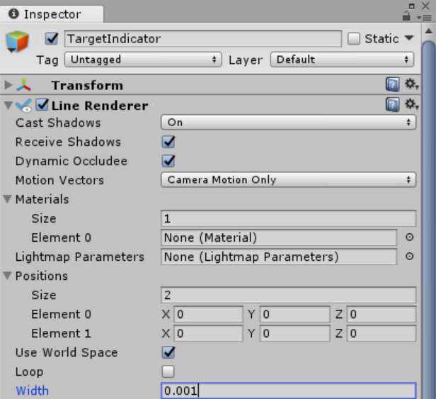
FIGURE 14-11 Configuring the LineRenderer component.
Now you need to set the color used by the LineRenderer component by creating a material. Follow these steps:
- In the Project window, create a new folder named Materials in the Assets folder.
- Right-click the Materials folder, choose Create, and select Material.
- Click the material and, in the Inspector, change its name to TargetIndicatorMaterial.
- Click the Emissive Color box. (See Figure 14-12.)
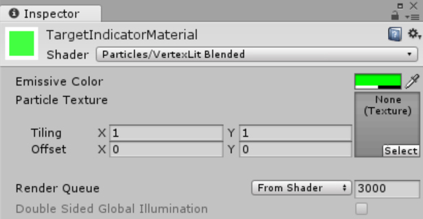
FIGURE 14-12 Configuring the TargetIndicatorMaterial. - In the color window that opens, set the R, G, B, A properties to 0, 255, 0, and 127, respectively. Then close the color window.
- Drag the TargetIndicatorMaterial object from the Project window onto the TargetIndicator object in the Hierarchy.
Implementing the Patrolling Script
You are now ready to implement the logic that will cause the Ethan model to continuously walk between two edges of the ReferencePlane object. (Vuforia will automatically position this plane.) This type of continuous movement between given positions is called patrolling. Basically, whenever the tracking state of the image target changes, either the OnTrackingFound or OnTrackingLost method of the DefaultTrackableEventHandler script will send a message to the Patrolling script, which will be responsible for controlling Ethan’s state.
To implement this logic, follow these steps:
- In the Project window, right-click the Scripts folder, choose Create, and select New C# Script. Name the new script Patrolling.
- Drag the Patrolling script from the Project window onto the Ethan object in the scene.
- Double-click the Patrolling script in the Project window to open it in Visual Studio.
- Replace the default
usingstatements in the header of the Patrolling.cs file with the following two statements:using UnityEngine;
using UnityEngine.AI; - Extend the class declaration with two instances of the
UnityEngine.RequireComponentAttribute:[RequireComponent(typeof(NavMeshAgent))]
[RequireComponent(typeof(Animator))]These attributes will ensure that the
NavMeshAgentandAnimatorcomponents will always be available for your script. If you do not add these components through the Editor, Unity will automatically add them to the object using the script. - In the
Patrollingclass, implement the helper method from Listing 14-4. This method obtains references to all components that will be used later, including the following:- NavMeshAgent This will be used to set the character’s path.
- Animator This will be used to animate the character.
- MeshRenderer This renders the reference plane, which will be used to determine the points between which Ethan will walk.
- LineRenderer This is a reference to the line renderer, which indicates where Ethan is going.
LISTING 14-4 Obtaining references to required components
private NavMeshAgent navMeshAgent;
private Animator animator;
private MeshRenderer referencePlaneRenderer;
private LineRenderer targetIndicator;
private void ObtainReferencesToRequiredComponents()
{
navMeshAgent = GetComponent<NavMeshAgent>();
animator = GetComponent<Animator>();
referencePlaneRenderer = GameObject.
Find("ReferencePlane").GetComponent<MeshRenderer>();
targetIndicator = GameObject.
Find("TargetIndicator").GetComponent<LineRenderer>();
} - Implement the
ConfigureAgenthelper method. (See Listing 14-5.) This method sets public properties of theNavMeshAgentinstance to configure Ethan’s linear and angular speeds, stopping distance, and braking mode. (The braking mode is set tofalse, so the Ethan model will not slow down as it approaches its destination.)LISTING 14-5 Configuring the agent’s properties
private void ConfigureAgent()
{
navMeshAgent.speed = 0.05f;
navMeshAgent.angularSpeed = 300.0f;
navMeshAgent.stoppingDistance = 0.01f;
navMeshAgent.autoBraking = false;
} - Use the preceding helper methods to implement the
Startmethod of thePatrollingscript. (See Listing 14-6.)LISTING 14-6 Initializing the Patrolling script
private void Start()
{
ObtainReferencesToRequiredComponents();
ConfigureAgent();
} - Implement the
UpdatePatrollingStatusmethod. (See Listing 14-7.) This method handles messages sent fromDefaultTrackableEventHandler.UpdatePatrollingStatusaccepts oneBooleanargument:isPatrolling. The value of this argument indicates whether or not Ethan should walk. Therefore,UpdatePatrollingStatususes the input argument to set the local memberisPatrolling, update theIsWalkinganimation parameter (refer to Chapter 11), and configure Ethan’s target position using another method,UdpateAgentDestination. Additionally,UpdatePatrollingStatussets theisStoppedproperty of theNavMeshAgentinstance to!isPatrolling. This ensures that Ethan will not be moved by Unity’s navigation engine when the image target is not recognized.LISTING 14-7 Updating the patrolling status
private bool isPatrolling;
private void UpdatePatrollingStatus(bool isPatrolling)
{
this.isPatrolling = isPatrolling;
animator.SetBool("IsWalking", isPatrolling);
navMeshAgent.isStopped = !isPatrolling;
UpdateAgentDestination();
}As shown in Listing 14-7, the
UpdateAgentDestinationmethod uses theboundsproperty of theMeshRendererassociated with theReferencePlaneobject. This property is represented as an instance of theUnityEngine.Boundsstruct and represents the bounding box of the plane. This property hasminandmaxproperties. They are both of typeVector3and represent minimum and maximum points of the box plane. Practically, these points are calculated as follows, where center denotes the middle point of the bounding box:
- The
minandmaxpoints are used to initialize a two-dimensional array of namedestinations. This collection stores objects of typeVector3. They define the locations between which Ethan will walk. To determine which of those points should be set as the next Ethan destination, implement a privatecurrentDestinationIndexmember, which stores an array index. As shown in Listing 14-8, the value ofcurrentDestinationIndexis incremented right after setting the new destination. However, the array index cannot be larger than the length of the array. Accordingly, an incremented value is then divided by the array length and thecurrentDestinationIndexis set to the remainder of that division (modulo operator).LISTING 14-8 Updating the agent destination
private int currentDestinationIndex = 0;
private void UpdateAgentDestination()
{
if (referencePlaneRenderer != null)
{
var destinations = new Vector3[]
{
referencePlaneRenderer.bounds.min,
referencePlaneRenderer.bounds.max
};
navMeshAgent.destination = destinations[currentDestinationIndex];
currentDestinationIndex = (currentDestinationIndex + 1) % destinations.Length;
}
} - Implement the
IndicateDestinationhelper method from Listing 14-9. This method dynamically sets thepositionsproperty of theLineRenderercomponent to draw the line (refer to Figure 14-11). One end of this line is set to Ethan’s current position, while the other is set to Ethan’s destination. So,IndicateDestinationdynamically shows Ethan’s current path.LISTING 14-9 Indicating the destination position
private void IndicateDestination()
{
if (targetIndicator != null)
{
targetIndicator.SetPositions(new Vector3[]
{
navMeshAgent.transform.position,
navMeshAgent.destination
});
}
} - Use the helpers to implement the
Updatemethod of thePatrollingscript as shown in Listing 14-10. This implementation checks whether theisPatrollingmember istrue(see the firstifclause). If so, the secondifclause is used to determine whether the agent’s path is not currently being calculated (see thepathPendingproperty) and whether the remaining distance is not smaller or equal to the agent’s stopping distance. If these logical conditions evaluate totrue, the agent’s destination is modified using theUpdateAgentDestinationmethod. (Refer to Listing 14-9.) Whenever the agent is patrolling the image target area, theIndicatePositionmethod is invoked to update theLineRendererto reflect the agent’s path.LISTING 14-10 Ethan’s destination is updated at every frame, provided the
isPatrollingmember istrueprivate void Update()
{
if (isPatrolling)
{
if (!navMeshAgent.pathPending
&& navMeshAgent.remainingDistance <= navMeshAgent.stoppingDistance)
{
UpdateAgentDestination();
}
IndicateDestination();
}
} - Extend the
OnTrackingFoundandOnTrackingLostmethods ofDefaultTrackableEventHandleras shown in Listing 14-11. When tracking is found or lost, this broadcasts theUpdatePatrollingStatusmessage to all child components (including Ethan). A Boolean parameter supplements the message to indicate whether Ethan should walk (truein theOnTrackingFoundmethod) or not walk (falsein theOnTrackingLostmethod).LISTING 14-11 Broadcasting a message to the child components
protected virtual void OnTrackingFound()
{
var rendererComponents = GetComponentsInChildren<Renderer>(true);
var colliderComponents = GetComponentsInChildren<Collider>(true);
var canvasComponents = GetComponentsInChildren<Canvas>(true);
// Enable rendering:
foreach (var component in rendererComponents)
component.enabled = true;
// Enable colliders:
foreach (var component in colliderComponents)
component.enabled = true;
// Enable canvas':
foreach (var component in canvasComponents)
component.enabled = true;
BroadcastMessage("UpdatePatrollingStatus", true);
}
protected virtual void OnTrackingLost()
{
var rendererComponents = GetComponentsInChildren<Renderer>(true);
var colliderComponents = GetComponentsInChildren<Collider>(true);
var canvasComponents = GetComponentsInChildren<Canvas>(true);
// Disable rendering:
foreach (var component in rendererComponents)
component.enabled = false;
// Disable colliders:
foreach (var component in colliderComponents)
component.enabled = false;
// Disable canvas':
foreach (var component in canvasComponents)
component.enabled = false;
BroadcastMessage("UpdatePatrollingStatus", false);
}
Testing the App
Let’s test the app to see how it works so far. Follow these steps:
- Click Play to start the Editor play mode.
- Place the image target in the camera’s FOV. As shown in Figure 14-13, both Ethan and the target indicator are properly displayed, and Ethan is walking. However, there is an extra gray plane below them, which blocks the image target.
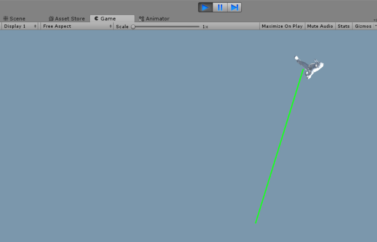
FIGURE 14-13 Unwanted boundary rendering. The gray plane is a product of the MixedRealityCameraParent object, which has a Boundary child object. The Boundary object renders the floor and boundaries of the headset’s user. Specifically, the ReferencePlane is interpreted as the floor, so the Boundary object renders a gray plane.
- To disable this unwanted effect, expand the MixedRealityCameraParent object in the Hierarchy and click the Boundary object.
- In the Boundary Inspector, deselect the Render Floor checkbox. (See Figure 14-14.)
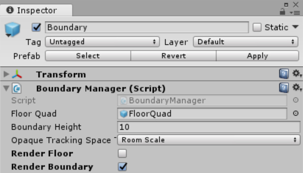
FIGURE 14-14 Disabling floor rendering. - Click Play to restart the Editor play mode. You should finally see the result shown in Figure 14-9.
Adding a Custom Image Database
You just learned how to use Vuforia to detect one of its own built-in image targets. For practical applications, however, you will likely want the app to recognize custom images rather than one of Vuforia’s predefined ones. To achieve this, you will need to create a custom image database. To find out how, read on.
Obtaining a Vuforia Developer License Key
Before you can create a custom image database, you must register as a Vuforia developer and obtain a Development License Key. Follow these steps:
- Enter the requested information on the following page to register as a Vuforia developer: http://bit.ly/Vuforia_registration.
- Once registered, log in to the Vuforia Development Portal (https://developer.vuforia.com/), accept the license terms, click Develop, and choose License Manager.
- In the License Manager, click the Get Development Key button.
- In the Add a Free Development License Key page (see Figure 14-15), type the name of the app in the App Name box (in this case, HoloAugmentedExperience), select the checkbox at the bottom of the page to agree to the terms and conditions, and click Confirm. A hyperlink for your new app will appear in the License Manager.
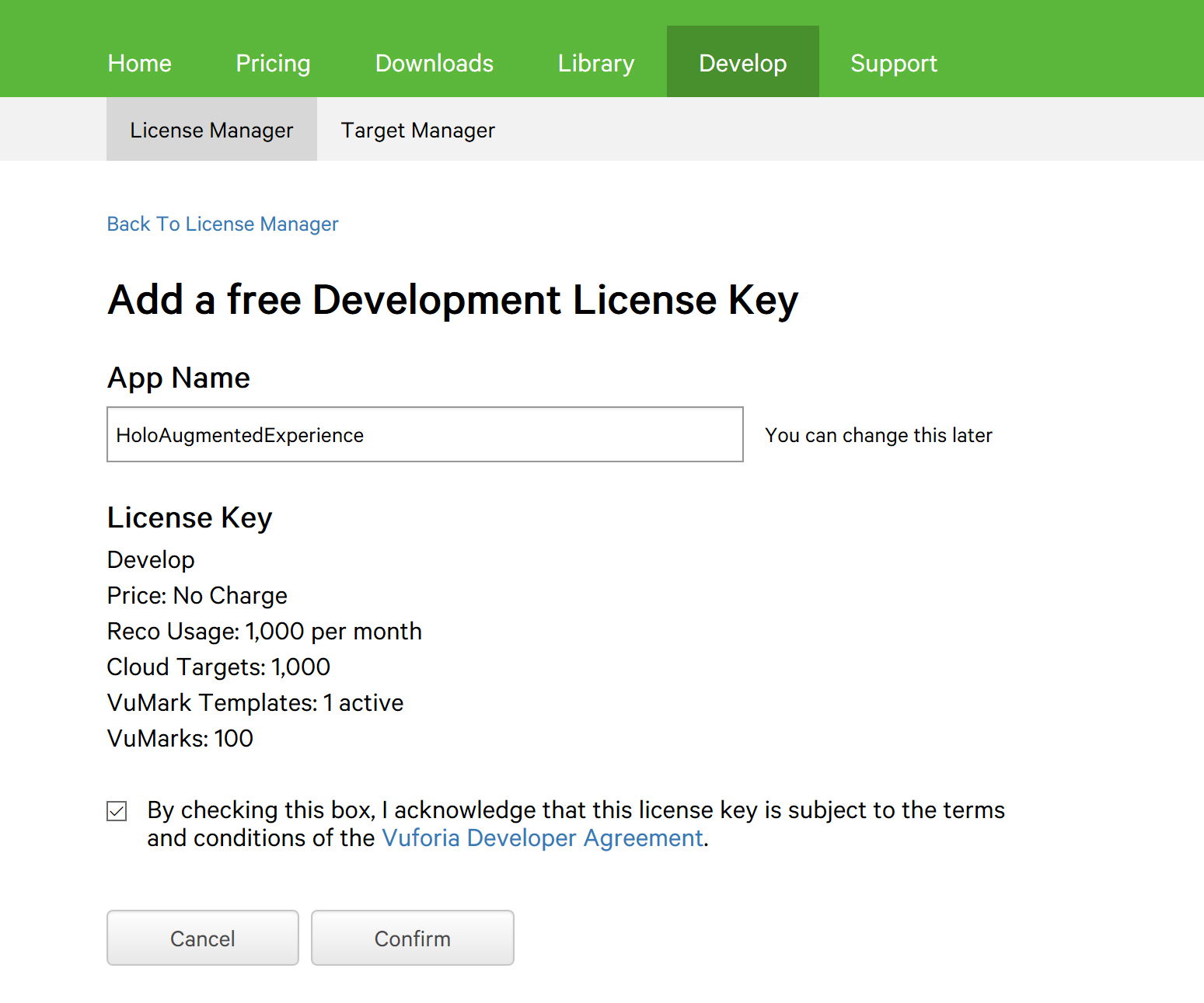
FIGURE 14-15 Obtaining a Vuforia Development License Key. - Click the hyperlink to obtain your Development License Key.
- Copy the Development License Key to the clipboard.
- In the Unity Editor Hierarchy, click the ARCamera object.
- In the ARCamera Inspector, scroll down to the Vuforia Behaviour (Script) group, and click the Open VuforiaConfiguration button.
- A VuforiaConfiguration group appears in the Inspector. Paste the Development License Key into the App License Key box. (See Figure 14-16.)
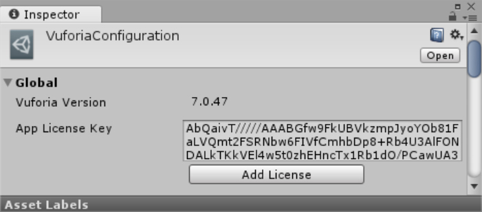
FIGURE 14-16 Configuring the Vuforia Development License Key.
Creating a Database
To create your custom image database, follow these steps:
- In the Vuforia Developer Portal, click Develop, and then click Target Manager. (See Figure 14-17.)

FIGURE 14-17 Target Manager. - Click the Add Database button. A Create Database dialog box opens. (See Figure 14-18.)
- Type CustomDatabase in the name box, select the Device option button under Type, and click the Create button. Vuforia creates a new database, which is displayed as a hyperlink in the Target Manager.
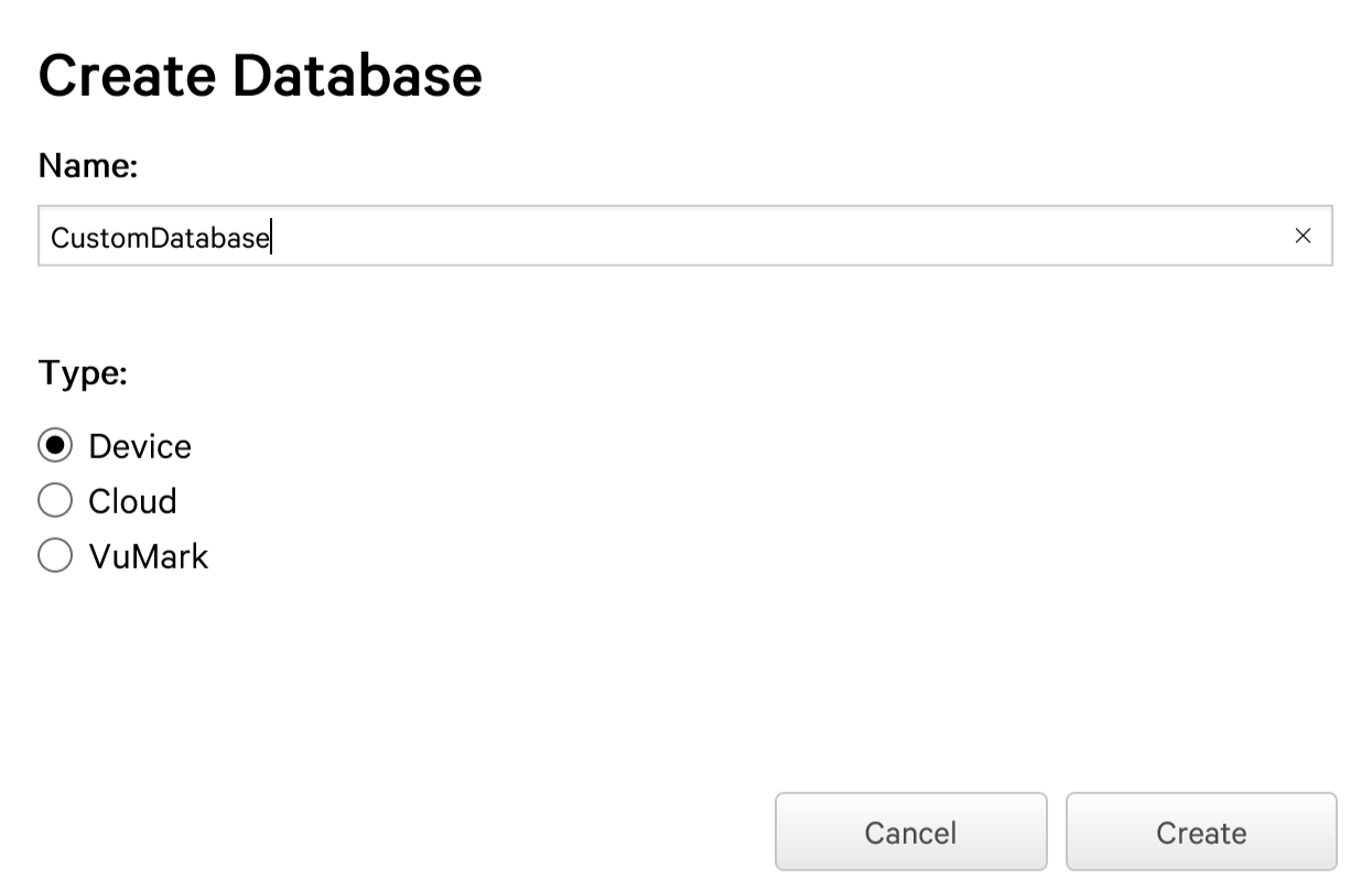
FIGURE 14-18 Creating a device-based database.
Notice in the Create Database dialog box that you can create three types of databases:
- Device Device-based databases are added to your app and used locally. They are recommended for AR apps that need to recognize fewer than 1,000 targets.
- Cloud Cloud-based databases are hosted within the Vuforia cloud. They’re used for apps that must recognize large numbers of targets—even more than 1 million. However, if you use this approach, the app user must have a network connection to access the database.
- VuMark These are databases for storing VuMarks. Each VuMark is represented as an SVG file. VuMarks let you design custom targets that represent a company logo or some other custom symbol. For a full description of VuMarks, see http://bit.ly/VuMarks.
Adding a Target
Initially, the custom database will contain no targets. To add a target, follow these steps:
- Click the CustomDatabase hyperlink in the Target Manager. A CustomDatabase window opens. (See Figure 14-19.)
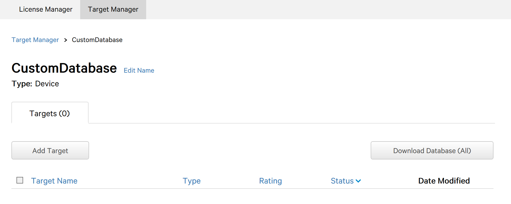
FIGURE 14-19 The CustomDatabase window. - Click the Add Target button.
An Add Target dialog box opens, which enables you to upload an image target. (See Figure 14-20.) You can choose between four types:
- Single Image Choose this to select an image file as the image target.
- Cuboid Choose this to select a cuboid as the image target. You can specify the cuboid’s width, height, and length.
- Cylinder Choose this to select a cylinder as the image target. You can specify the cylinder’s height as well as the diameter of its base and top.
- 3D Object Choose this to use Vuforia Object Scanner data. (Available for Android only.)
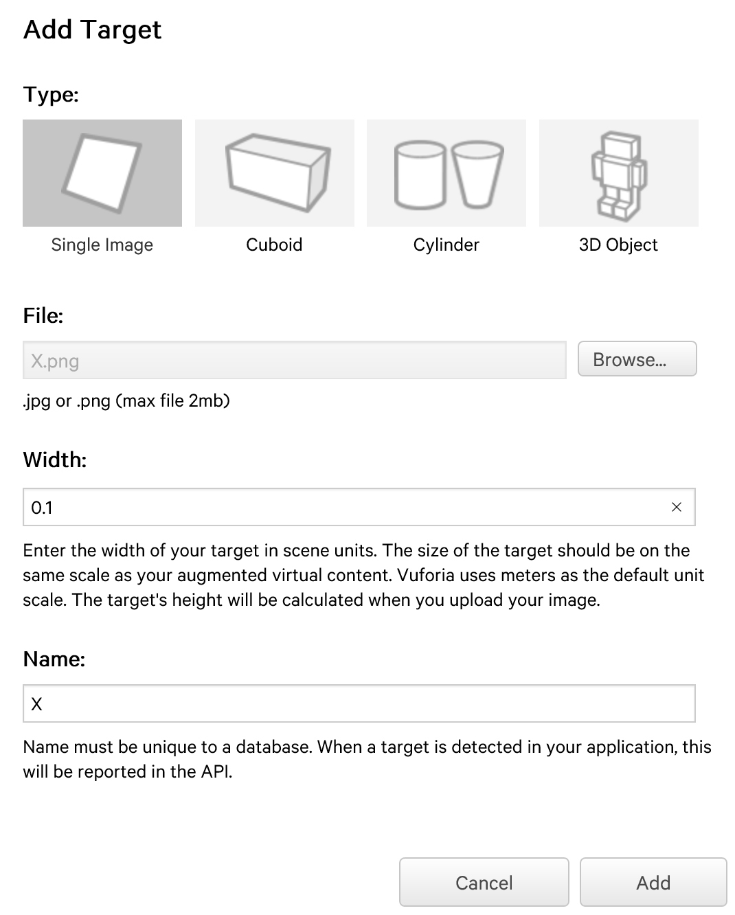
FIGURE 14-20 Adding an image target. - Click the Single Image option under Type.
- Click the Browse button and locate and select the image file you want to use. (For this example, I selected a simple 380 x 500-pixel bitmap of a black X on a white background.)
- In the Width box, type a value to specify the width of the image target. Vuforia will use this value to calculate the image target’s height automatically; Unity Editor will apply these dimensions to scale the target. (I entered 0.1 to produce an image target roughly as wide as the astronaut used earlier.)
- Type a name for the image target in the Name box to identify it in the database. (I named my image target X.)
- Click the Add button to upload the image to the database.
Downloading the Database and Importing It into Unity
Your next step is to download the database containing the image target and import it into Unity. Follow these steps:
- Click the Download Database button on the Target Manager page. (Refer to Figure 14-19.)
- In the window that appears, select Unity Editor as the database format. Then click the Download button. The database is saved as a custom Unity package.
- In Unity Editor, open the Assets menu, choose Import Package, and select Custom Package.
- Locate and select the database you just downloaded.
- The Import Unity Package dialog box opens. (See Figure 14-21.) Ensure that all objects are selected, and click Import.
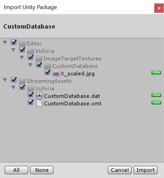
FIGURE 14-21 Importing a custom database.
Selecting the Custom Image Target
Now that you’ve imported the database, you can select the custom image target for use in your app. Follow these steps:
- Select the ImageTarget object in the Hierarchy.
- In the ImageTarget Inspector, in the Image Target Behaviour (Script) group, open the Database drop-down list and choose CustomDatabase.
- The Image Target drop-down list is updated to contain any image targets within the selected database. In this case, the database contains only one image target: X. (See Figure 14-22.) Select X from the Image Target drop-down list. The X image will replace the astronaut image in the Scene view.
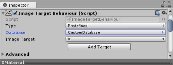
FIGURE 14-22 Setting the image target to the custom image. - To ensure that the custom database is loaded and activated, open the ARCamera Inspector and, in the Vuforia Behaviour (Script) group, click the Open VuforiaConfiguration button.
- Expand the Databases setting and select both the Load CustomDatabase Data checkbox and the Activate checkbox underneath it. (See Figure 14-23.)
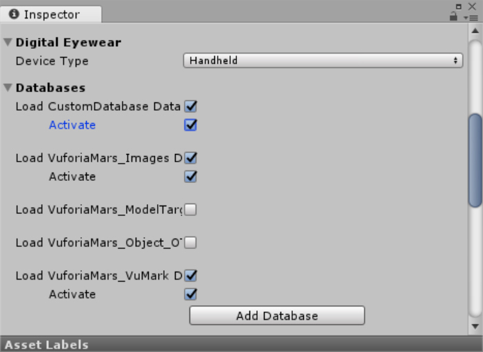
FIGURE 14-23 Loading and activating the target database. - To test the app, you need to print out the image or send it to your phone. Then, click the Play button to start Unity Editor Play mode and place the image target within the camera’s FOV. You should see Ethan walking on this new image target.
Tip
If the size of the custom image target differs significantly from that of the astronaut image, you will need to adjust the scale of the ReferencePlane as well as the width of the LineRenderer accordingly.
Configuring for HoloLens
You’ve created a custom image target. Now all you need to do is enable the integration of Vuforia with HoloLens. Here’s how:
- Open the ARCamera Inspector and, in the Vuforia Behaviour (Script) group, click the Open VuforiaConfiguration button.
- Expand the Digital Eyewear setting, open the Device Type drop-down list, and choose Digital Eyewear.
- Open the Device Config drop-down list that appears and choose HoloLens.
- Deploy the app to the HoloLens device and test it. (Note that you cannot test Vuforia in the HoloLens emulator.)
Summary
In this chapter you learned how to create augmented reality experiences with Vuforia. Specifically, you created an app that recognizes image targets and then overlays virtual content on top of them. In this example the virtual content was a character that moved intelligently between two corners of a bounding box around the image target. The presented content applies to HoloLens only because immersive headsets do not provide AR experiences.