
The first law of thermodynamics, which was the main focus of the previous chapter, is basically the principle of the conservation of energy. It asserts that energy should be conserved in physical processes but it does not delineate a direction for physical processes. Hence, this chapter will discuss the second law of thermodynamics which concisely sets a particular direction for all processes, and examine its implications on heat engines and related systems.
In nature, certain processes are observed to only proceed in a single direction spontaneously, though other processes that are consistent with the conservation of energy are seemingly possible. A cup of hot coffee will lose heat to its cool surroundings but never gain heat from it, without any external work, though the latter is perfectly coherent with the first law of thermodynamics. The very notion of temperature does not help either. The zeroth law of thermodynamics only implies that when two objects are in thermal equilibrium, they have the same temperature. It does not dictate the direction of heat conduction.
More generally, the classical laws so far are temporally reversible. That is, if you take a video of an egg that is dropped onto the ground, so precise that you can track the motion of individual atoms, and reverse the video such that a cracked egg reverts to a complete egg, the system in reverse will still obey all the classical laws that have been introduced. Therefore, this replay is permissible. However, we know from common experience that this never seems to occur. Therefore, a new law — known as the second law of thermodynamics — is needed to prescribe the direction of evolution of a system.
The second law of thermodynamics can be stated in various, equivalent forms which are remarkably succinct. The two most intuitive ones are Kelvin-Planck’s statement and Clausius’ statement. Kelvin-Planck’s statement asserts that it is impossible to construct a perpetual motion machine of the second kind — a cyclic engine whose sole effect is to absorb heat from a heat reservoir and produce an equivalent amount of work done. Note that a heat reservoir is defined to be a large repository of internal energy (as compared to the system it is connected to) such that its temperature stays approximately constant throughout heat transfer. As a concomitant of Kelvin-Planck’s statement, an engine that is 100% thermally efficient is precluded. Clausius’ statement, on the other hand, purports that it is impossible to construct a device that solely transfers heat from a body of lower temperature to one of higher temperature. Note that the word “solely” in the context of the two statements implies that there should not be any changes imposed on the external environment.
These seemingly disparate statements are actually equivalent, as we shall show later, but for now, let us examine their ramifications on the feasibility of various processes. Due to these axioms, some processes are deemed to be impossible. Consequently, processes can be categorized as reversible or irreversible. A reversible process is an evolution of a system from an initial state to a final state such that there is a process that allows the system to return to its initial state without leaving any changes to its surroundings. An irreversible process does not satisfy this requirement. An important fact to understand is that a process is deemed irreversible only if you try every path from the final state to the initial state (the path is not necessarily the original movie played in reverse) and the above criterion is still not fulfilled.
Lastly, note that a system can always be reverted from a final state to its initial state, regardless of whether the original process is reversible or irreversible. However, this reversion may involve changes to the external surroundings of the system if the original process was irreversible. Ultimately, the reversibility of a process is a completely different concept from whether a system can be restored to its original state — the former concerns whether a system can be reverted without leaving any traces of the occurrence of the original process.
Reversible processes are idealizations and do not exist in reality, both because of inherent irreversibilities, such as friction, in practical processes and the infeasibility in meaningfully using a reversible process, as we shall see. As a result of Kelvin-Planck’s and Clausius’ statements, the following processes are irreversible.
It is impossible to reverse any process in which heat due to friction is produced. A fraction of work done is inevitably converted to heat by friction. In order to reverse the process, this heat must be converted back to an equivalent amount of work done which violates the Kelvin-Planck’s statement. In a similar vein, it is impossible to reverse any process that occurs too quickly. If the intermediate states of a system are not in thermodynamic equilibrium, frictional losses and turbulence will arise and these are irreversible based on the previous argument. Therefore, a reversible process must first be quasistatic — implying that it would take eons for a reversible process to be completed.
Direct heat transfer from a high-temperature body to a low-temperature body with a finite temperature difference is also irreversible due to Clausius’ statement. Since heat transfer can only occur across a temperature gradient between two bodies, a reversible heat transfer process is physically impossible. However, we can “cheat” for theoretical purposes by putting two bodies with an infinitesimal temperature difference in thermal contact to approximate a reversible heat transfer process. Such a conceptual process is infeasible in real life as it would take an eternity for a significant amount of heat to be spontaneously transferred.
Finally, it is also impossible to reverse a process in which a gas expands or contracts without performing work or absorbing heat. An example of such a phenomenon is a gas escaping a ruptured membrane to fill up the evacuated portion of a thermally insulated container — this process is known as a Joule expansion and will be analyzed later. We can prove this by contradiction. Suppose that there were a reverse process for Joule expansion. Then, one could first run an isothermal expansion from an initial state to a final state to absorb a certain amount of heat and produce an equivalent amount of work (as internal energy does not vary in an isothermal process). Afterwards, running the reverse Joule expansion process1 would yield a cyclic system which absorbs a certain amount of heat to produce the same amount of work — hence violating Kelvin-Planck’s statement. As another corollary, the process of mixing different gases is also irreversible as it is effectively two Joule expansions of two gases.
A heat engine works by receiving heat from a heat source and producing work. Its process is cyclic so that it can produce a steady output. As the operation cannot be perfectly efficient — as forbidden by Kelvin-Planck’s statement — some exhaust heat must be dumped into a heat sink so that the system can return to its initial state. The schematic in Fig. 3.1 summarizes the design of a heat engine.
Figure 3.1:Heat engine
In a single cycle, the heat engine draws QH amount of heat from the high-temperature reservoir and deposits QL amount of leftover heat while producing W = QH – QL amount of work. There must be zero net heat or work flowing into the heat engine during a cycle as the internal energy of the heat engine must remain unchanged after a single cycle.
Next, a refrigerator works in a different way — its essential function is to extract heat from a low-temperature reservoir and to deposit it in a high-temperature reservoir. In practice, heat is constantly transferred from the lower-temperature refrigerant to the higher-temperature room in order to keep the refrigerator cold. However, this cannot occur spontaneously, as precluded by Clausius’ statement. Therefore, a refrigerator is a cyclic system that operates by receiving a certain amount of work to bring some heat from a low-temperature reservoir to one of higher temperature.
Referring to Fig. 3.2, in every cycle, the refrigerator extracts QL amount of heat from a low-temperature reservoir and transfers QH amount of heat to the high-temperature reservoir, requiring W = QH – QL amount of external work in the process.
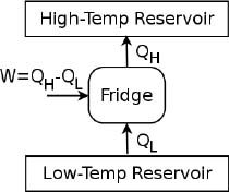
Figure 3.2:Refrigerator
With an understanding of how heat engines and refrigerators work, we shall now prove the equivalence of Kelvin-Planck’s and Clausius’ statements by contradiction. Suppose there exists a device that violates Kelvin-Planck’s statement. Then, we can use it as a heat engine and connect its output to a refrigerator such that it supplies the necessary external power to the refrigerator. Both devices are connected to the same low-temperature and high-temperature reservoirs.
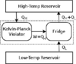
Figure 3.3:Conceptual set-up
As shown in Fig. 3.3, the hypothetical engine receives QH heat from the high-temperature reservoir and delivers W = QH amount of work to the refrigerator. The refrigerator then draws QL heat from the low-temperature reservoir and stores QH + QL heat in the high-temperature reservoir. Now, closely observe the part of the system that is enclosed by the dotted lines (the combined system comprising the heat engine and refrigerator). If we were to place it inside a black box (no peeking!) and observe its effects from the outside, we would obtain the equivalent system in Fig. 3.4 which acts as a refrigerator.
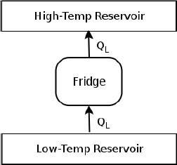
Figure 3.4:Equivalent system
The equivalent system effectively draws QL amount of heat from the low-temperature reservoir and deposits it completely into a high-temperature reservoir — a phenomenon that is forbidden by Clausius’ statement. Thus, we have proven that if Kelvin-Planck’s statement is violated, Clausius’ statement would be violated as well. To prove the converse, we consider a similar set-up. Suppose there exists a device whose sole effect is to deliver QL amount of heat from a low-temperature reservoir to a high-temperature one. Then, we can use this system as a refrigerator to continuously pump the heat, deposited during a heat engine cycle, back into the heat source.

Figure 3.5:Conceptual set-up 2
Referring to Fig. 3.5, a heat engine absorbs QH heat from a high-temperature reservoir and releases QL heat back into a low-temperature reservoir, producing W = QH – QL amount of work to an external system in the process. The hypothetical refrigerator then pumps QL heat from the low-temperature reservoir back into the heat source. By considering the heat engine, refrigerator and the heat sink as a whole, one would obtain a heat engine which absorbs QH – QL amount of heat from the heat source and produces W = QH – QL amount of work — a perfectly thermally efficient device which is forbidden by Kelvin-Planck’s statement. Having proven the converse, we have shown that Kelvin-Planck’s and Clausius’ statements are in fact equivalent.
Kelvin-Planck’s and Clausius’ statements prescribe a theoretical limit on the efficiencies of heat engines and refrigerators — measures that we shall now quantify. Since the purpose of a heat engine is to produce useful work, the efficiency η of a heat engine is defined as the work produced W divided by the total amount of heat input QH.

where QL is the total heat deposited into heat sinks. In general, QH is not necessarily extracted from a single heat source and can be accumulated across different heat sources at different junctures in a heat engine cycle. Similarly, heat can also be deposited into various heat sinks at different instances. However, for this section, we will solely be studying systems operating between two reservoirs which means that these systems can only exchange heat with this fixed pair of reservoirs and nothing else.
Since the purpose of a refrigerator is to extract heat from a low-temperature reservoir, the efficiency of a refrigerator is quantified by the ratio of the total amount of heat extracted to the external work received. This measure is known as the coefficient of performance (COP).

It should be noted that the COP can be greater than unity (this is why the misleading word “efficiency” is not used for refrigerators). Proceeding to the main topic, Carnot deduced certain principles concerning these efficiencies from Kelvin-Planck’s and Clausius’ statements. Carnot’s principles state that
(1)An irreversible heat engine is less efficient than a reversible heat engine when operating between the same two heat reservoirs. The COP of an irreversible refrigerator is smaller than that of a reversible refrigerator when operating between the same two reservoirs.
(2)The efficiencies of all reversible heat engines operating between identical pairs of heat reservoirs are the same. Accompanying this, the coefficients of performance of all reversible refrigerators operating between identical pairs of heat reservoirs are the same.
We can prove the two claims by contradiction. A crucial component of our proofs would entail the fact that a reversible heat engine, unsurprisingly, can be reversed to operate as a refrigerator with the same QH, QL and W (except that they are in the opposite directions) and vice-versa. Beginning with the first principle, we assume that an irreversible heat engine is more efficient than a reversible heat engine. We then connect this irreversible heat engine and the reverse of the reversible heat engine (a refrigerator) to the same pair of heat reservoirs in Fig. 3.6.
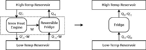
Figure 3.6:Conceptual set-up 3
The irreversible heat engine extracts  heat from the source and produces W amount of work which is used to power the refrigerator. The exhaust heat is then – W. The refrigerator then extracts QH – W heat from the low-temperature reservoir and deposits QH amount of heat into the high-temperature one. Since the efficiency of the irreversible heat engine is greater than that of the reversible heat engine (which is currently running in reverse),
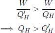

Now, consider the combined system of the heat engine and refrigerator. Its sole effect is to deliver QH – amount of heat from the low-temperature reservoir to the high-temperature reservoir, in contravention of Clausius’ statement. Therefore, the efficiency of an irreversible engine must be less than or equal to that of a reversible engine. However, the equality case cannot hold — if not, the fridge will be the reverse process for the irreversible heat engine (as the combined system of the heat engine and fridge results in no heat and work everywhere) and thus violate the premise. The efficiency of an irreversible engine must then be less than that of a reversible engine. In the case of refrigerators, one can assume that an irreversible refrigerator has larger COP than a reversible refrigerator and consider a similar set-up by running the reversible refrigerator in reverse as a heat engine that supplies work to the irreversible refrigerator. The combined setup would then violate Clausius’ statement — leading to the conclusion that the COP of an irreversible refrigerator is smaller than that of a reversible refrigerator.
To prove the second claim, compare two reversible engines A and B. Suppose that A is more efficient than B. Then, one can use A as a heat engine, in replacement of the irreversible heat engine, and run B in reverse as the refrigerator in the previous set-up. Then, one would conclude that A must be less efficient or equally efficient as B. Afterwards, one can reverse the roles of A and B to conclude that B must also be less efficient or equally efficient as A. Therefore, A and B must have the same efficiency. Since a reversible refrigerator is its equivalent reversible heat engine in reverse, the coefficient of performance of the refrigerator and the efficiency of its equivalent heat engine can be related, if the heat reservoirs remain unchanged. From the definitions of efficiency and COP and the facts that the magnitude of the heat transfers and work are the same,

Therefore, if all reversible heat engines have the same η, all reversible refrigerators should also have the same COP. Lastly, take note that these arguments did not mention the working substance — the medium facilitating the process — of the heat engines or refrigerators. Then, the efficiencies and COPs of reversible heat engines and refrigerators across a constant pair of reservoirs are independent of their working substance. This means that the efficiencies of a reversible heat engine that uses an ideal gas as its medium and one that uses a real gas are the same across the same two reservoirs!
Thermodynamic Temperature
In this section, we shall study how the efficiency of reversible heat engines can be used to formalize the definition of temperature through the Kelvin scale. We have just concluded that the efficiency of a reversible heat engine is independent of the engine process and the working substance. Then, the efficiency η, and thus  , can only be functions of the temperatures of the high-temperature and low-temperature heat reservoirs, TL and TH.

Now, observe that we can choose the reversible heat engine that operates between a high-temperature reservoir at temperature TH and a low-temperature reservoir at temperature TL as one that consists of the two reversible heat engines and a middle-temperature reservoir at temperature TM in Fig. 3.7.

Figure 3.7:Engine comprising two reversible heat engines
The combined system, enclosed in dotted lines, is still a reversible heat engine operating between the two reservoirs. Now, we know that

where QM is the heat delivered via the middle reservoir. Then,
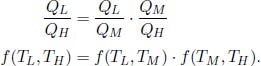
Observe that the left-hand side is independent of TM. The only way for this equation to be satisfied is for
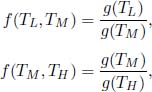
for some function g(T) so that the terms in TM cancel. That is, in general,
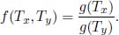
Therefore, for a heat engine receiving QH from a heat source at temperature TH and depositing QL into a heat sink of temperature TL,

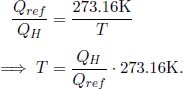
We can choose any monotonic function g(T) — the exact function will determine how the temperature scale is defined. Lord Kelvin chose the simplest function g(T) = T and established his Kelvin scale. On this scale, the ratio between two temperatures is equal to the ratio between the heat transferred to and from a reversible heat engine connected to reservoirs of those two temperatures. This definition of temperature is independent of any thermometric, physical property — such as the expansion of mercury — and is thus known as a thermodynamic scale. Lastly, we need to have a reference temperature in order to define all other temperatures. In accordance with international standards, 273.16K is defined to be the triple point of water (the unique temperature at which the solid, liquid and gaseous phases of water co-exist). Then, all other temperatures can be defined by setting TL or TH as 273.16K. For example, suppose that a heat engine connected between a heat source at temperature T and a heat sink at 273.16K draws QH heat from the source and deposits Qref heat into the sink. Then the temperature T in Kelvins, is given by
Thankfully, this novel thermodynamic scale does not differ much from the previously pervasive Celsius scale. The magnitude of an additional Kelvin is in fact equal to the magnitude of an additional degree Celsius and the conversion formula between Kelvins and degree Celsius is

As a result of the Kelvin temperature scale, the efficiency of a reversible heat engine operating between a heat source and sink at respective temperatures TH and TL is by definition
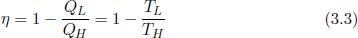
where TL and TH are measured in Kelvins.
Now that we have established that a reversible engine is the most efficient when operating between a pair of heat reservoirs and have determined its efficiency, let us analyze the criteria required for such an engine to be reversible.
Firstly, the operation of the engine must be frictionless and quasistatic, as we have previously shown that processes involving friction are irreversible. Secondly, when the engine exchanges heat with a reservoir, the engine’s temperature must be identical to the reservoir’s temperature. This point is less obvious so we shall provide a formal proof. Referring to Fig. 3.8, use a reversible heat engine to deliver work to its refrigerator counterpart (which exists due to its reversible nature), while operating between the same pair of heat reservoirs.
Observe that if we isolate the engine, refrigerator and heat sink, this combined system withdraws QH from the heat source and returns it back — all while leaving no traces in itself and external entities. Therefore, the transfers of QH between the engine and the heat source as well as between the refrigerator and the heat source must be reversible! The only way for this to occur is when the engine and refrigerator temperatures are equal to that of the heat source during the process of heat exchange. By considering the engine, refrigerator and heat source as a combined system, we can similarly deduce that the engine and refrigerator temperatures must be identical to that of the heat sink during their interactions.
Figure 3.8:Reversible heat engine and refrigerator (reverse engine)
With this knowledge, we can now construct a reversible heat engine. There can only be two states of the engine — when it is exchanging heat with a reservoir and when it is not. In the case of the former, its temperature, must be equal to the reservoir’s temperature, so the only way for it to exchange significant heat is to undergo an isothermal process (at the reservoir’s temperature). In the case of the latter, since the engine cannot interact with other entities beside the reservoirs by assumption, it can only undergo an adiabatic process. As such, we have drastically narrowed down the possible processes (absent of frictional losses) of a reversible engine that operates between a pair of reservoirs.
Now, the total number of reversible engines with the maximum efficiency  actually depends on a slight technicality in the definition of efficiency. When we say that the engine withdraws QH amount of heat from the heat source, one perspective is that the engine can only receive heat from the heat source at each juncture and cannot lose any heat to it (i.e. it is a oneway heat flow of QH). Another perspective is that the engine can receive and return heat from and to the heat source, for a net heat intake of QH . Evidently, the former definition is more restrictive, but it is in fact the more pervasive one. This is because in a more general cycle which interacts with a multitude of reservoirs, the heat sources and sinks are not labeled for us. We then usually take the reservoirs that the system gains or loses heat from and to as the heat sources and sinks respectively. That is, when we are computing the total heat input to a system (for efficiency calculations), we can simply add the values of heat influxes and ignore the heat outflows.
Adopting the former perspective, there is in fact only one set of processes that a reversible system operating between two reservoirs can undergo. Visualizing the PV diagram of our engine, we have two enforced isotherms (at the temperatures of the reservoirs) and only adiabats to connect them. A reversible heat engine operating between two reservoirs must thus entail two isotherms and two adiabats, as depicted in Fig. 3.9.

Figure 3.9:Carnot cycle
(1) 1 → 2: An isothermal expansion
(2) 2 → 3: An adiabatic expansion
(3) 3 → 4: An isothermal compression
(4) 4 → 1: An adiabatic compression
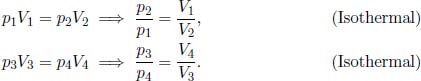
In particular, the Carnot engine follows this set of operations and uses an ideal gas as its working fluid. Now, let us practice deriving the efficiency of a heat engine by verifying Eq. (3.3) for the Carnot engine. In this derivation, it is important to note that the engine only receives heat during process 1 → 2 from a heat source of temperature TH and deposits heat during process 3 → 4 to a heat sink of temperature TL. Let the pressure, volume and temperature of the ith state of the ideal gas system (i ranges from 1 to 4) in the Carnot engine be pi, Vi and Ti. Note that T1 = T2 = TH and T3 = T4 = TL as there cannot be a finite temperature difference during a reversible heat transfer. By the ideal gas equation,
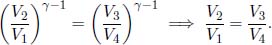
Based on the adiabatic condition,

Dividing the former equation by the latter and substituting the results we obtained from the two equations at the top,
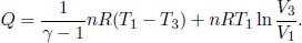
The heat absorbed during process 1 → 2, QH, and the heat ejected during 3 → 4, QL, can be calculated by the first law of thermodynamics since the internal energy of a gas does not change during an isothermal process.

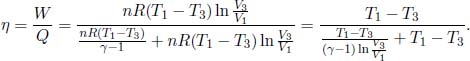
There is a negative sign in front of QL as it is defined to be the heat ejected from the system during process 3 → 4 (and not heat supplied to the ideal gas). Thus, the efficiency of a Carnot engine is
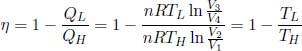
where we have used the fact that the ratios of the volumes are equal. This is to be expected as we have precisely defined temperature according to the Kelvin scale to ensure this!
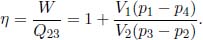
Scrutinizing the efficiency of a reversible heat engine that is operating between two heat reservoirs at temperatures TL and TH, we observe that

If we now standardize the sign of heat flow such that heat supplied to a system is positive while heat extracted from a system is negative, we have for a reversible engine

as QL was previously defined to be a positive quantity that represents the heat extracted from the system into a heat sink. Rearranging,

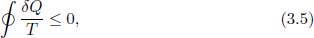
Note that QL and QH are the only heat exchanges of the system with an external environment and these exchanges must occur when the system is at temperature TL and TH respectively (as there cannot be a finite temperature gradient during a reversible heat transfer). Therefore, we can write the above sum as a path integral along the cycle that the system takes

where δQ is an infinitesimal heat transfer (positive if it is a heat input) and T is the instantaneous temperature of the system along the path it takes. The loop superimposed on the integral underscores the fact that this path is a complete cycle (i.e. starts and ends at the same point). Note that the integrand is only non-zero when the system is exchanging heat with the two reservoirs and hence evaluates to the previous sum above. We see that the integral of  over a reversible engine cycle operating between two reservoirs must be zero! This brings us to the question of determining this integral along general cycles, both reversible and irreversible. The answer to this is Clausius’ inequality.
Clausius’ Inequality: For any arbitrary cyclic process that a closed system undergoes,
where δQ is an infinitesimal heat transfer into the system and T is the instantaneous temperature of the system at each juncture along its path. A closed system refers to a system in which no mass exchange with an external environment occurs. The equality case holds if and only if the cycle is internally reversible.
Now, it is important to make a distinction between internal and external irreversibilities (we have held this off till now). We will only consider closed systems. An internally reversible process is one in which no irreversibilities, such as friction and heat transfer between components of a system with a finite temperature gradient, occur within a system. Due to this definition, an internally irreversible process that a system undergoes must be quasistatic. However, irreversibilities at the boundaries of the system, such as heat transfer between the system and its external environment across a finite temperature difference, is still allowed. A process involving a system is externally reversible if no irreversibilities occur during the interaction of the system and its environment at their boundaries. Lastly, a process is totally reversible if it is both internally and externally reversible. This total reversibility is what we have been considering up till now.
Proof of Clausius’ inequality: A closed system undergoing a general cyclic process may be connected to various reservoirs of different temperatures at different junctures along the cycle. Then, let the ith reservoir in the process2 have a temperature Ti in Fig. 3.10. Its temperature is matched to the instantaneous temperature of the system during their point of interaction. Now, consider the following hypothetical set-up where all of the reservoirs, that are in direct correspondence with the system, are connected to a common principal reservoir of temperature Tp via reversible engines. Each engine may function as a heat engine or a refrigerator.

Figure 3.10:System connected to an array of heat reservoirs
During the ith infinitesimal step along the cycle, the principal reservoir supplies a certain amount of heat to the ith reversible engine which produces δWi amount of work in the process. The ith engine also transfers δQi heat to a reservoir of temperature Ti, which in turn delivers δQi heat to the system. We can in fact relate δWi to δQi as the facilitator is a reversible engine which obeys
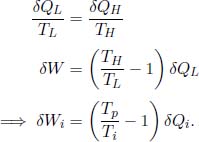
In a single complete cycle, which comprises myriad such infinitesimal steps, the system takes in a net heat of  and hence produces
  amount of work. It cannot keep any heat as internal energy because it returns to its original state. Note that the system does not directly contravene Kelvin-Planck’s statement as some δQi may be negative — implying that some heat flows out of the system too. With that out of the way, consider all auxiliary reservoirs and the system as a combined system in Fig. 3.11.
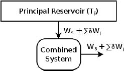
Figure 3.11:Equivalent system
The net effect of the combined system is seemingly to absorb  amount of heat from the principal reservoir and produce an equivalent amount of work. Since this is forbidden by Kelvin-Planck’s statement,

Substituting 
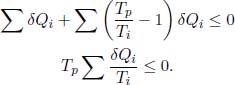
Changing the above from a discrete sum to a closed loop integral (by imagining the hypothetical set-up as a continuous, infinite series of reservoirs) and dividing by Tp which is a positive quantity,

for an arbitrary cyclic process taken by the system. Since we have matched the temperatures of the auxiliary reservoirs to the instantaneous temperature of the system, T here represents the temperature of the system so this inequality strictly involves only quantities of the cyclic system.
To show that the equality case must hold if the cycle is internally reversible, we first realize that an internally reversible cycle of the system is fully reversible in this context as it only interacts with heat reservoirs with infinitesimal temperature gradients. Now, suppose that the integral is negative such that  is negative in the previous set-up. Then, reversing the system and all the reversible heat engines would yield a combined system with a positive — an evident contradiction as it violates Kelvin-Planck’s statement.
To show that an irreversible cycle must result in a negative value of the closed loop integral, suppose that the integral results in zero such that is zero. Then, the combined system, comprising the set of reser voirs and the system, draws no heat from the principal reservoir and performs zero net work on the external environment. The states of the interior of the combined system — the system and the reversible engines — have not changed either as all processes are cyclic. The combined system thus results in no change to the environment and itself — showing that each part of it must be totally reversible and contradicting the premise of the irreversibility of the original system. The equality case then occurs if and only if the cycle is internally reversible.
Clausius’ inequality implies that

for any internally reversible, cyclic process. A subscript has been added to highlight the fact that this cycle must be internally reversible. As this integral is zero for all such cycles, the following integral from an initial state 1 to a final state 2 via an internally reversible route is solely dependent on the initial and final states.
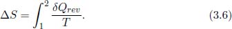
The above integral is defined as the change in entropy from state 1 to 2, ΔS. Though the calculation of ΔS is performed over an internally reversible path, the entropy changes between an initial and final state along all paths are the same — the system can even undergo an irreversible process. ΔS is only dependent on the initial and final states of a system and the absolute entropy S, assuming that it exists,3 is a state function that is defined uniquely for each state of the system.
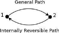
Figure 3.12:Cycle
Referring to Fig. 3.12, consider a cyclic process where a system takes a general route, internally reversible or irreversible, from an initial state 1 to a final state 2 and takes an internally reversible route back to the initial state. Applying Clausius’ inequality,

where the first integral is along the general path and the second integral is along the internally reversible route. Rearranging,
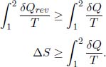
Now for an isolated system which involves no mass and heat transfer, δQ is zero such that

The entropy of an isolated system can only increase! This is another common statement of the second law of thermodynamics. The equality case only occurs when the process in the system is internally reversible. Applying this idea to the entire universe (the set of all particles) which is considered as an isolated system, the entropy of the universe can only increase!
We can use this notion of entropy to determine whether a process in a system A is totally reversible. Since the entire universe contains all possible systems, including those that system A interacts with, the process in A is totally reversible if and only if this process, with respect to the entire universe, is internally reversible (since external reversibilities of the process with respect to A also become internal irreversibilities of the universe). Then, the process in a system is totally reversible if and only if it does not result in a net entropy change of the universe. At this juncture, we may be confused by internal and external irreversibilities. The distinction between them is entirely dependent on the choice of the system as the following example shall illustrate.
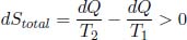
Problem: Consider two bodies of different temperatures T1 and T2 that are brought into thermal contact with T1 > T2. An infinitesimal amount of heat, dQ, is transferred from the high-temperature body to the low-temperature body. The two bodies only interact with each other and not other parts of their surroundings. Is the high-temperature body undergoing an internally reversible process? What about the low-temperature body? What about the combined system? Which of the above systems are isolated systems? Find the entropy changes of each body and the entire universe.
The one-body systems are both undergoing an internally reversible process as heat transfer with an external system is not counted as an irreversibility within the system. The combined system comprising both objects does not undergo an internally reversible process as there is heat transfer within components of the system. Only the system comprising both objects is an isolated system as there is no heat transfer between this system and its surroundings. The infinitesimal changes in entropy of the high-temperature and low-temperature bodies are

The net change in entropy of the entire universe is the sum of these changes.
as dQ is a positive quantity and T1 > T2. As expected of an irreversible process, the entropy change of the universe is positive. Incidentally, this also shows that the entropy version of the second law of thermodynamics implies Clausius’ statement. If T1 < T2, the entropy change of the universe is negative — a result that is forbidden by ΔS ≥ 0. Since we have already shown that Kelvin-Planck’s and Clausius’ statements result in ΔS ≥ 0 and because we have just proven the converse, these three versions of the second law of thermodynamics are equivalent.
The key to evaluating entropy changes is to actually ignore the process that a system actually undergoes as entropy is a state function. However, we must keep track of the system’s initial and final states and then identify a reversible path along which entropy changes can be computed.
Entropy Change of a Heat Reservoir
If a heat reservoir, maintained at constant temperature T, receives Q amount of heat, its entropy change is

This is the simplest case of a system receiving heat as its temperature does not vary. However, there are still a few subtleties in writing the above expression as we must ensure that the process that we use in computing the entropy change is indeed internally reversible. The Q amount of heat may not be dumped into the reservoir as one lump sum as the reservoir may not go through a series of equilibrium states (though it is extremely large). Therefore, it is best to inject heat sparingly on many different occasions and to sum all the individual entropy changes to compute the total entropy change. Since the total sum of these interspersed heat inputs is still Q and the temperature is always T, the above expression is valid.
Entropy Change of a System with a Constant Heat Capacity
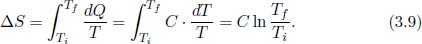
A body of a constant heat capacity C receives or loses heat to an external system such that its temperature changes from Ti to Tf. To determine its change in entropy, consider the quasistatic process where heat is injected or ejected in infinitesimal amounts on each occasion, over infinitely many occasions. This could be attained theoretically by connecting the body to a series of reservoirs that establish an infinitesimal temperature difference with the current temperature of the body. The body is always in thermodynamic equilibrium and the process is internally reversible. Each infinitesimal amount of heat dQ received results in an infinitesimal change in temperature  . Therefore, the entropy change of the body is
Entropy Change of Ideal Gases
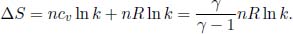
If n moles of an ideal gas with a specific heat capacity at constant volume cv undergoes a process such that its temperature and volume changes from Ti and Vi to Tf and Vf respectively, its entropy change is
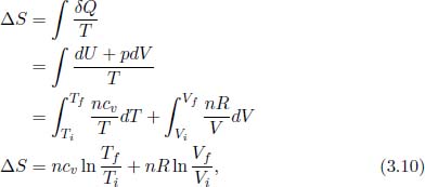
since δQ = dU + δWby by the first law of thermodynamics and δWby = pdV for an internally reversible process that we have chosen for the integration. We reiterate the fact that the above expression is valid regardless of the actual process that the gas undergoes. It does not matter if the process is non-quasistatic — such that the gas is not always in equilibrium — as the entropy change is dependent only on the initial and final states.
Joule Expansion
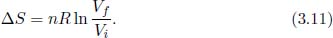
A thermally insulated rectangular container of total volume Vf is initially separated into two regions by a membrane. The left side of the divider contains an ideal gas of volume Vi and temperature T while the right side is empty. A large hole is then punctured on the membrane such that the gas begins to expand freely and finally attains equilibrium. What is the entropy change of this process?
As the container is thermally insulated, there is no heat transfer between the gas and the container. Since there is no work done on or by the gas, as there is nothing to resist the gas’ expansion, the internal energy of the gas remains constant. Since the internal energy of a gas is strictly only dependent on the gas’ temperature, the temperature of the gas stays constant throughout. Therefore, the entropy change of this process is that of a reversible isothermal expansion of a gas from volume Vi to Vf (even though the actual process is a non-equilibrium process). Substituting Ti = Tf = T into Eq. (3.10),
This example emphasizes how the entropy change of an irreversible process should still be calculated via a reversible path between the same initial and final states.
Based on the definition of entropy, we know that for an internally reversible process,

where δQ is the infinitesimal heat supplied to a system at temperature T and dS is the infinitesimal change in entropy of the system (which is a state function and thus has an actual derivative). On another note, the work done during an internally reversible process on a system by an external agent is

Therefore, the first law of thermodynamics yields

for an internally reversible process. However, observe that the equation above is expressed entirely in terms of state variables. Then, Eq. (3.12) must hold for all processes, reversible or irreversible! Eq. (3.12) is known as the fundamental relation of thermodynamics and relates the changes in the state variables of a system that has a uniform pressure and temperature. To further convince yourself that the above equation is valid for all processes, consider the following. The first law of thermodynamics states that

and this is valid for all processes, both reversible and irreversible. In an irreversible process,4 δWon > –pdV or δWby < pdV. For example, some possible work by the system could have been converted to heat due to friction. and is thus rendered useless. However, in an irreversible process, δQ < TdS as implied by Clausius’ inequality. Equation (3.12) just implies that the differences in δWon and δQ in reversible and irreversible processes exactly cancel out!
Usually, the external environment of a system imposes constraints on the evolution of a system. Suppose that the relevant system only interacts with its surroundings which has instantaneous temperature Text and pressure pext. In an infinitesimal process, the system gains δQ heat from its environment — resulting in an entropy change of  in the environment. The entropy change of the system dS must thus satisfy

for the total entropy change of the universe to be non-negative. Applying the first law of thermodynamics δQ = dU + δWby, where dU is the change in internal energy of the system and δWby is the work done by the system,

If the work done by the system is only that against its external environment, δWby = pextdV where dV is the change in volume of the system. Thus,

where the equality case only holds for a totally reversible process of the system.
A spontaneous process is defined as one that can (not will) occur in one direction without any external intervention (defined as inputting work or heat through media besides the surroundings of the system). Since a spontaneous process is foremost irreversible — else, its reverse process can also occur — we can investigate the conditions for spontaneity under different constraints via the inequality case of the above relationship. However, keep in mind that these are not the only criteria to spark off a reaction as they simply govern whether a process is possible and not whether it will actually take place.5
(a)Isolated System: Since δQ = 0 for an isolated system, Eq. (3.13) implies

for a spontaneous process. The equilibrium state is thus the state of maximum entropy.
(b)A Solid (Classical Physics): Since the volume of a solid is approximately constant and its molecules are fixed (such that its entropy cannot vary significantly), dV = 0 and dS = 0. We then require

for a spontaneous process — a familiar property in classical mechanics. The equilibrium state is thus the state of minimum internal energy.
(c)System at Constant Entropy and External Pressure: In such cases where there is work performed, we are in a slight conundrum as we ideally wish to express everything in terms of properties of the system but δWby is only related to pext. To circumvent this, we can simply look at states where the system has attained mechanical equilibrium with its environment such that its pressure is p = pext. The process between a pair of such states is then most generally a finite process. As dS = 0 and pext is constant, Eq. (3.13) for a finite step requires

Since the system’s pressure is p = pext in its initial and final states,

for a spontaneous process, where H is the enthalpy of the system. Notice that the possibility of the intermediate states possessing pressures that differ from pext does not affect this result since H is a state function.
(d)System at Constant Volume and External Temperature: In this case, we only consider states of the system that have attained thermal equilibrium with the external environment (i.e. the system’s temperature is T = Text). Since dV = 0 and Text is constant, Eq. (3.13) for a finite step is

As the system’s temperature is T = Text in its initial and final states,

for a spontaneous process, where A = U – TS is the Helmholtz free energy of the system.
(e)System at Constant External Temperature and Pressure: Since pext and Text are constant, Eq. (3.13) for finite processes is

Using a similar procedure as above, we only consider equilibrium states of the system whose pressures and temperatures are equal to those of the external environment. Then, since p = pext and T = Text in the initial and final states of the system,

for a spontaneous process, where G = H – TS is the Gibbs free energy of the system. Chemists are the most familiar with this condition as their experiments are often conducted under standard laboratory environments (fixed pressure and temperature).
Problems
Heat Engines and Refrigerators
1.Heat Pump**
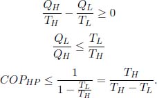
Besides the heat engine and refrigerator, there is a third common appliance known as the heat pump. The main objective of a heat pump is to deliver heat to a high-temperature system. It operates by receiving a certain amount of external work W = QH – QL to withdraw heat QL from a low-temperature reservoir of temperature TL and depositing heat QH into the high-temperature reservoir (the system) of temperature TH > TL. Suggest a measure for the performance of a heat pump (call it the coefficient of performance COPHP) and express the maximum COPHP in terms of TL and TH .
As a concrete example, a building at temperature T is heated by a heat pump which uses a river at temperature T0 as a heat source. The heat pump, which has the ideal performance, consumes a constant power W while the building loses heat to its surroundings at a rate α(T – T0), where α is a constant. Show that the equilibrium temperature of the building, Te > T0, is given by

2.Brayton Cycle**
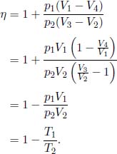
A Brayton cycle uses an ideal gas as its working substance and consists of the four following reversible steps. The ideal gas is first compressed adiabatically and then expanded isobarically. Afterwards, it is further expanded adiabatically and finally compressed isobarically to its initial state. Determine the efficiency of this engine in terms of the temperatures of the first and second states, T1 and T2.
3.Otto Cycle**
An Otto cycle uses an ideal gas with an adiabatic index γ as its working substance and consists of the four following reversible steps. The ideal gas is first compressed adiabatically and its pressure is then increased isochorically. Afterwards, it is expanded adiabatically and its pressure is finally decreased isochorically to its initial value. Determine the efficiency of this engine in terms of the volumes of the first and second states, V1 and V2, and γ.
4.Stirling Cycle**
A Stirling cycle uses an ideal gas with an adiabatic index γ as its working substance and consists of the four following reversible steps. The ideal gas is first expanded isothermally and its pressure is then decreased isochorically. Afterwards, it is compressed isothermally and its pressure is isochorically increased to its initial value. Determine the efficiency of this engine in terms of the volumes of the first and third states and γ.
5.Is Carnot Still the Most Efficient?**
We have shown that the Carnot engine is the most efficient engine when operating between two heat reservoirs with temperatures TH and TL (TH > TL), whereby its efficiency is given by  . Now, suppose that you are given a series of reservoirs with temperatures ranging between TL and TH and are asked to construct a heat engine that interacts with any subset of these reservoirs. Show that the efficiency of an engine with internal irreversibilities (e.g. friction) but a well-defined temperature at every juncture (i.e. its process is quasistatic such that it is always in an equilibrium state) is smaller than that of an internally reversible engine following the same cycle of equilibrium states (hint: use Clausius’ inequality). Next, prove that the efficiency of an internally reversible engine constructed with the given reservoirs is no larger than the Carnot efficiency . This shows that a Carnot engine operating between the highest and lowest temperature reservoirs is still the most efficient when a series of reservoirs with intermediate temperatures is available.
The Second Law and Entropy
6.Gaseous Processes*
Determine the entropy change of n moles of a gas with an adiabatic constant γ in expanding from an initial volume V to a final volume kV under isothermal and isobaric conditions.
7.Mixing*
A thermally insulated container of total volume V is separated by a frictionless divider into two compartments A and B that have volumes αV and (1 – α)V respectively. n moles of a certain gas fills compartment A and a certain amount of a different gas fills compartment B such that the system is in equilibrium. Determine the entropy change, of the system comprising the two gases, associated with mixing the two gases by removing the divider and waiting till the system attains thermodynamic equilibrium once again.
8.Connected Vessels*
Two thermally insulated vessels of volumes V1 and V2 initially contain n1 and n2 moles of different monoatomic gases that are at pressures p1 and p2. These vessels are then connected by a thermally insulated tube. After the system of vessels equilibrates, determine the change in entropy of the universe.
9.Transferring via a Carnot Engine**
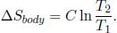
A small body with constant heat capacity C is placed in direct thermal contact with a large reservoir of temperature T2 such that its temperature is changed from T1 to T2. Determine the entropy changes of the body, reservoir and the universe. Show that the entropy change of the universe is nonnegative regardless of the relative magnitudes of T1 and T2. Now if the heat is delivered to or extracted from the small body via a Carnot engine operating between the large reservoir and the small body, determine the entropy changes of the body, reservoir and the universe.
10.Verifying the Second Law**
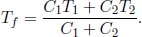
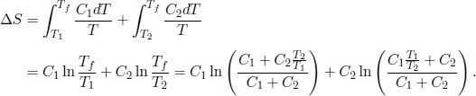
Two substances of heat capacities C1, C2 and initial temperatures T1 and T2 are placed in thermal contact. They are isolated from their surroundings. When thermal equilibrium is subsequently achieved, determine the entropy change of the universe and show that it must be non-negative.
11.Maximum Work Done**
Determine the maximum work obtainable from a heat engine connected to two reservoirs of constant heat capacities CH and CL at initial temperatures TH and TL < TH .
12.Pushing a Piston**
A cylindrical container is separated by a fixed divider with a valve and a frictionless piston is attached to its open right end. The walls of the cylinder, divider and piston are perfect thermal insulators. The cylinder is filled with 12g of helium in the left compartment and 2g of helium in the right. Initially, the pressures, volumes and temperatures of the gases are respectively, 6atm, 11.2L and 273K in the left side, and 1atm, 11.2L and 273K in the right side. The specific heat capacity (note that this is per unit mass) of helium at constant pressure is cp = 5.25J/g K. The piston is pushed towards the divider by a reversible compression until the pressure on the right side equals 6atm. At this juncture, the valve opens and the whole system is allowed to reach equilibrium. What is the final equilibrium temperature? Find the total entropy change of the whole process. (Singapore Physics Olympiad)
13.Reversible Heat Transfer**
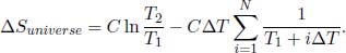
A body of constant heat capacity C is heated up from a temperature T1 to T2 by bringing it into thermal contact and waiting till it establishes thermal equilibrium with N large reservoirs of temperatures T1 + ΔT, T1 + 2ΔT, . . . ,T1 + (N – 1)ΔT, T2 in ascending order of temperature, where  . Determine the net entropy change of the universe due to this process. Then, take the limit of N → ∞ and ΔT → dT where dT is an infinitesimal change in temperature and show that this process is reversible.
1.Heat Pump**
Since the primary aim of a heat pump is to deliver heat QH via external work W, its coefficient of performance is
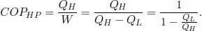
There are various ways to show that the maximum COPHP occurs when the heat pump is a Carnot cycle in reverse. The most direct way to do this is to observe that COPHP = COPFR + 1 where COPFR is the coefficient of performance if we used the heat pump as a refrigerator. Since COPFR is maximized when the refrigerator is reversible (reverse Carnot cycle), COPHP is maximized when the heat pump is a reverse Carnot cycle. Another method is to exploit the fact that the entropy change of the universe must be nonnegative due to a heat pump cycle. Then,
Next, when the building is at its equilibrium temperature Te, its rate of heat loss to its surroundings must be equal to its rate of heat gain from the heat pump.
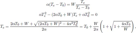
where we have chosen the root that is greater than T0.
Note: In our following solutions for heat engines and refrigerators, the ith state is defined to have pressure pi, volume Vi and temperature Ti.
2.Brayton Cycle**
The system takes in heat during process 2 → 3 and releases heat during process 4 → 1.

where cp is the isobaric molar heat capacity of the gas medium. The total work done by the gas in a single cycle is the net heat supplied to the ideal gas as its internal energy remains constant.

The efficiency is then

To simplify the above expression, we know from the adiabatic condition, applied to processes 1 → 2 and 3 → 4, that

The efficiency can be expressed as
3.Otto Cycle**
The engine absorbs heat during process 2 → 3 and ejects heat during process 4 → 1.

where cv is the molar heat capacity of the gas at constant volume. The total work done by the gas in a single cycle is the net heat supplied.

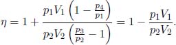
The efficiency is then
To simplify the above expression, apply the adiabatic condition to processes 1 → 2 and 3 → 4.
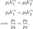
Then,
Since 
4.Stirling Cycle**
The work done by an ideal gas in a reversible isothermal process in which its volume changes from Vi to Vf is

The work done by the ideal gas during processes 1 → 2 and 3 → 4 are

The total work done by the gas is then
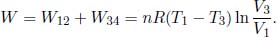
The ideal gas absorbs heat during processes 4 → 1 and 1 → 2. The former heat absorbed is 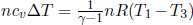 while the latter is the work done by the gas from 1 → 2, W12, as its internal energy remains constant during an isothermal process.
The efficiency of the engine is then
5.Is Carnot Still the Most Efficient?**
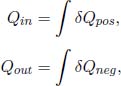
Since the internal energy of an engine does not change after a cycle, the efficiency of a heat engine is

where Qin is the sum of the positive values of heat influxes while Qout is the sum of the positive values of heat outflows. By Clausius’ inequality,

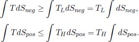
for any infinitesimal process (the equality case holds when the process is internally reversible). Now, we shall classify the various δQ and dS’s into positive quantities and negative quantities. The positive quantities are labeled as δQpos and dSpos while the absolute values of the negative quantities are labeled as δQneg and dSneg. Then,
while Clausius’ inequality implies that

Therefore,
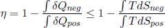
where the equality case only holds for internally reversible engines. We have hence proven the first claim. To prove the second one, observe that
Furthermore,

as  for the cycle to return to its original state (since entropy is a state function). The efficiency of an internally reversible engine is

6.Gaseous Processes*
We will be using Eq. (3.10). During an isothermal expansion,

During an isobaric expansion, the pressure is constant. Since the volume of the gas expands by k times, its temperature must also increase by a factor of k by the ideal gas law. Then,
7.Mixing*
The two gases initially have a common temperature and pressure. In order for the pressures to be balanced, the number of moles of gas molecules in compartment B must be

After the removal of the divider, the two gases undergo free expansion, just like the Joule expansion. Their final common temperature must be the same as their initial common temperature as energy is conserved (the walls of the container are insulated). Therefore, the total change in entropy is the sum of the two changes in entropy associated with the free expansions of the two gases. By Eq. (3.11),

8.Connected Vessels*
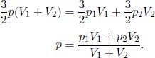
We need to determine the final pressure p of the combined set-up. Since the system is thermally insulated, its total energy must be the same. Its initial energy is 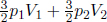 Then,
Then,
Next, we will need to calculate the final temperature of the combined system Tf. By the ideal gas equation,
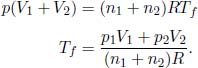
Applying Eq. (3.10) to the two gases, the total change in entropy of the universe is
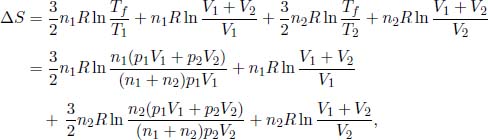
where T1 and T2 are the initial temperatures of the respective vessels.
9.Transferring via a Carnot Engine**
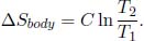
In the first case, the body receives C(T2 – T1) amount of heat. Therefore, the entropy change of the large reservoir is

as the reservoir correspondingly loses C(T2 – T1) amount of heat (which is possibly negative though). The entropy change of the body is given by Eq. (3.9),
The entropy change of the universe is the sum of the two above entropies.
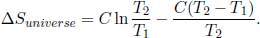
Defining a new variable  ,
,

Substituting x = 1, we obtain ΔSuniverse = 0 which is expected. Now consider
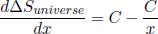
which is negative when x < 1 and positive when x > 1. Coupled with the fact 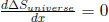 when x = 1, x = 1 is a local minimum and
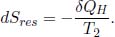
  0 for all x. In the second case, the entropy change of the reservoir is different as it needs to supply more heat (as some of the heat is converted to work by the Carnot engine). Then, let t be the instantaneous temperature of the body, δQH be the infinitesimal heat extracted from the reservoir and δQL be the infinitesimal heat delivered to the body in a single infinitesimal cycle (note that δQH and δQL are possibly negative). The infinitesimal change in entropy of the reservoir due to this infinitesimal Carnot engine cycle is
We also know that for a Carnot engine,

Then,

The entropy change of the body remains the same as its initial and final states are identical to those in the first case, 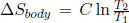 . The total entropy change of the universe is then

which is expected of a Carnot engine as it is reversible.
10.Verifying the Second Law**
Denoting the final equilibrium temperature of the two substances as Tf, the conservation of internal energy implies that
The total entropy change of the universe is
Defining 
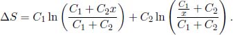
When x = 1, ΔS = 0 as expected. Furthermore,

which is negative when x < 1 and positive when x > 1. Since = 0 when  x = 1, x = 1 is a local minimum — implying that ΔS ≥ 0.
Alternatively, we can apply the AM-GM inequality as follows:

where k is a real number such that kC1 and kC2 are integers and where T1 and T2 are included kC1 and kC2 times respectively. Then,
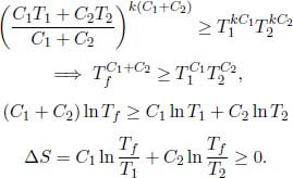
The equality only holds if T1 = T2.
11.Maximum Work Done**
Let the final common temperature of the reservoirs be Tf. Then, the total work done by the heat engine is

by the first law of thermodynamics. We then seek to minimize Tf. Let the instantaneous temperatures of the two reservoirs be tH and tL respectively. Applying the second law of thermodynamics to an infinitesimal heat engine cycle,
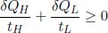
where δQH and δQL are the infinitesimal heat supplied to the heat source and sink, respectively. Since δQH = CHdtH and δQL = CLdtL, integrating over the relevant limits would yield

Therefore,

12.Pushing a Piston**
When the piston is pushed towards the divider, the gas on the right undergoes an adiabatic compression. When the valve is opened subsequently, mixing occurs and an equilibrium is attained.
Let Ti, Tf, Pi and Pf denote the initial and final temperatures and pressures of the right gas before and after the compression (immediately before the mixing). By the adiabatic condition,

where we have substituted Ti = 273K, Pi = latm, Pf = 6atm and γ =  for a monoatomic gas (helium). When the gases are mixed, the total internal energy in the cylinder must remain constant. Denoting nl and nr as the number of moles of helium in the left and right compartments respectively,
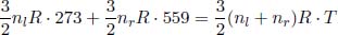
where T is the final equilibrium temperature. Since nl = 6nr,

There is no entropy change during the adiabatic compression. To study the entropy change due to the mixing, observe that the final equilibrium pressure is still 6atm. This is because the total internal energy of the set-up is conserved during the mixing and the initial total internal energy is (by the ideal gas law) 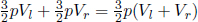 where Vl and Vr are the volumes of the left and right gases before mixing while p = 6atm. The final total internal energy is
  where pf is the final equilibrium pressure. Therefore, pf = p. Since the final equilibrium pressure is still 6atm, the entropy change of each gas is equivalent to that of it undergoing a reversible isobaric process from its initial to final temperature.

where ml and mr are the masses of the gases originally in the left and right compartments respectively.
13.Reversible Heat Transfer**
By considering the initial and final states of the body and applying Eq. (3.9), the total entropy change of the body is
Moving on, observe that the ith reservoir of temperature T1 + iΔT is responsible for increasing the body’s temperature from T1 + (i – 1)ΔT to T1 + iΔT. The heat transferred from the reservoir to the body in this process is CΔT. Then, the change in entropy of the ith reservoir is evidently  where the negative sign indicates that it loses heat. The total entropy change of the universe due to the entire procedure in the question is the sum of the entropy changes of the body and the reservoirs.
As N → ∞ and ΔT → dT, the latter sum becomes an integral. The total entropy change of the universe is then

which shows that this process is reversible!
1In order for a reverse Joule expansion process to be the reverse process of an isothermal process, the final and initial temperatures of a Joule expansion must first be identical. This is indeed the case as the gas does no work (there is no external pressure) and does not receive any heat during a Joule expansion.
2We will consider the case of discrete reservoirs first, for the sake of clarity.
3It actually does but this is beyond the scope of this book and is not germane here.
4Actually, this result is really proven from the fundamental relation of thermodynamics and Clausius’ inequality but intuition guides us to the result as well. Since dU = δQ + δWon = TdS – pdV and δQ < TdS, δWon > –pdV for irreversible processes.
5We also have to take into account the kinetics of the process in general (whether the process will proceed readily).
