 components of the vector due to various possible orientations of the coordinate axes. However, these all describe the same unique vector.
This chapter will study relativistic kinematics from the two fundamental postulates of special relativity. Special relativity is one of the more exciting and popular topics due to its profound consequences, many of which are contrary to common sense. Many apparent paradoxes will arise but one should note that special theory is a perfectly sound and coherent theory. Most of the time, these situations are not paradoxical at all and are contradictory purely because we made them to be so. Hopefully, these puzzles will be conducive to our understanding of the theory and help us to acclimatize to the strange phenomena in relativity. It may be helpful to dispel ourselves of our “common sense” in approaching this topic and accept the concepts on a clean slate — given that many effects feel extremely counter-intuitive.
There is a ubiquitous misconception that special relativity is incapable of analyzing accelerating objects or accelerating frames of reference. The former had better be false as any kinematic theory would be utterly useless if it could not describe acceleration. In fact, accelerating objects are relatively easy to handle as their motions can still be quantified in an inertial frame. Accelerating frames are much harder but can still be dealt with, in a manner similar to classical mechanics in a non-inertial frame (notice that Newton’s laws are only valid in inertial frames), though it will not be elaborated in this chapter.
Finally, you will notice that most special relativity problems do not involve gravity. Well, it turns out that special relativity was not the most accurate theory for systems with gravity — general relativity is. This is to be expected as special relativity was not designed as a theory of gravitation in the first place! In fact, Einstein’s special relativity was partly inspired by electromagnetism, as evidenced by the title of his famous 1905 paper: On the Electrodynamics of Moving Bodies. Nevertheless, the idea of objects on Earth experiencing a uniform, constant downwards force remains a decent approximation for our purposes.
A frame of reference is an important concept in relativity and physics in general. A frame of reference sets a standardized state of motion such that physical quantities, such as displacement and velocity can be measured relative to that frame. It is pivotal in ascribing meaning to a measurement as physical measurements are relative. For example, you may observe a car to be traveling at a certain velocity towards you when you are stationary with respect to the ground. However, if you run towards the car, you will then observe that it moves at a greater velocity with respect to yourself. Evidently, there is little meaning in proclaiming that the velocity of an object is a certain value without explicitly mentioning the frame of reference in which it was measured.
Events are of particular concern in physics and we quantify them with respect to certain frames of reference. Similar to how organizing real-life meetings requires a venue and a time, events have spatial and temporal coordinates in a certain frame of reference. However, there is a distinction between a frame of reference and a coordinate system.
Formally, the frame of an observer is a set of infinite virtual or tangible points that move rigidly with the observer such that they are perpetually at rest simultaneously in the frame of the observer. There is no relative motion (i.e. their separations do not vary) between individual particles or between a particle and the observer in the frame of the observer. These particles set a standardized state of motion at every point such that a physical quantity at a point in space can be measured with respect to a particle at that same point in space. Furthermore, there exists a universal time for all the particles in the frame such that the time of an event at a point in space in a certain frame can be defined to be that recorded by a particle of that frame at that same point in space.
A coordinate system, on the other hand, is merely a construct used to quantify measurements in a frame. A frame can have infinitely many possible coordinate systems. In that sense, a coordinate system is merely a mathematical language used to describe observations in a frame. Consider a vector in a frame, assuming that a Cartesian coordinate system is chosen, there can be many different values for the components of the vector due to various possible orientations of the coordinate axes. However, these all describe the same unique vector.
To define an event, a coordinate system must have spatial axes, which are usually Cartesian in special relativity, and a temporal axis. To visualize a coordinate system, we can imagine three infinite rows of meter sticks, extending from an observer who is usually defined as the origin of the coordinate frame, and a clock held by every particle that is perennially at rest in the frame of the observer. These clocks are synchronized in the frame of the observer; the possible methods of synchronization will be elaborated later.
The spatial coordinate of an event along a certain coordinate axes is then quantified by the number of meter sticks between the origin and the location of that event along the infinite row of meter sticks extending in that direction. The temporal coordinate of an event is then the reading of a clock at the spatial location of the event.
The first postulate in special relativity states that
•All inertial frames of reference are equivalent. That is, the laws of physics hold as well in one inertial frame as in any other inertial frame.
First and foremost, we have to understand the meaning of the term “relativity”. The principle of relativity is a creed that physicists believe in — we trust that the laws of nature are symmetric and elegant on the fundamental level. The principle of relativity is an intuitive axiom that ordains all laws of physics to exist in similar forms to observers in certain frames of reference. If this were not the case, physical laws would have severely limited utility and predictive power.
The notion of relativity extends way back to the times of Galileo and Newton. Galileo identified an extremely important class of frames of reference, known as inertial frames, in which the laws of motion are observed to be the same.1 Formally, an inertial frame is a frame of reference, whose geometry is Euclidean, in which all laws of physics appear in their simplest forms (i.e. no fictitious forces). Free particles, which are not subjected to net forces, undergo rectilinear motion at a constant velocity or remain stationary in an inertial frame. Furthermore, any frame that moves rectilinearly at a constant velocity relative to an inertial frame is also an inertial frame. In his development of classical mechanics, Newton hypothesized the existence of an absolute space and that the distant stars were stationary relative to the frame of absolute space. Thus, by considering the frame of fixed stars, all other inertial frames can be defined. However in the context of special relativity, the notion of an absolute space seems superfluous and is thus dismissed. After all, why should the frame of fixed stars be so special? In either case, inertial frames are a class of infinite frames of reference that travel at a constant velocity with respect to each other. In order for the laws of physics to hold in their simplest forms in all space, inertial frames must be non-accelerating.
One of the defining consequences of the principle of relativity is the relativity of velocity. Because of the uniformity of the physical laws across all inertial frames, it is impossible for an observer to identify the exact inertial frame that he is in. A common depiction of this usually goes as follows. Given your adventurous and playful nature, you sneak into a train that is initially stationary with respect to the ground. You decide to settle down in your new “camp” and thus, carry on with your daily activities. You rinse your mouth with a cup of water when you wake up, read this book under a candle light and play billiards. However, on one night, the train departs while you are sleeping and then travels at a uniform velocity relative to the ground. Will you be able to conclude that you are on a train, that is moving with respect to the ground, the next day, solely by conducting experiments inside the train? Assume that the windows are clamped shut so that you are unable to peek outside the train.
From your perspective, nothing has changed. If you hit a billiard ball under the exact same conditions as those on the previous day, the exact same results will be observed. If you toss a basketball vertically upwards, it will still land at the same spot on the floor from which it was thrown. It is impossible for you to conclude that the train you are on is moving with respect to the ground — this is the crux of the principle of relativity. It guarantees that traveling at a constant velocity with respect to the ground leaves no impact on the world around you.
Since we are unable to distinguish between inertial frames due to the principle of relativity, we are unable to isolate a truly stationary inertial frame, if it even exists. Velocity then becomes an inherently relative concept as we are unable to say whether something is “moving”, we can only conclude that something is moving with respect to something else — this is the relativity of velocity. When describing velocity, it is always paramount to mention what the velocity was measured with respect to.
Though velocity is relative, acceleration still remains absolute as the laws of physics are no longer presumed to be uniform across accelerating frames. Returning to the previous thought experiment, if the train speeds up or slows down abruptly, you will definitely be able to tell that a change in the train’s velocity has occurred. The surface of the water in your cup tilts, the candle flame slants and you slam into your seat due to a fictitious force. Because of the mutability of the physical laws across accelerating frames, an observer is able to determine whether he or she is accelerating and even quantify the acceleration.
Now, you may oppose the absoluteness of acceleration by posing the following problem: if you, an observer, measure a particle to have a certain acceleration in your frame, how can you tell it is you who accelerates and not the particle or a combination of both? The answer is that you can observe a free particle (i.e. another particle). If it has an acceleration in your frame, you know that you are accelerating (as a free particle should travel at a constant velocity when you are not accelerating). Furthermore, the magnitude of your acceleration will also be reflected by that of the free particle. Afterwards, you can determine the absolute acceleration of the first particle by taking into account your own acceleration and its acceleration in your frame. For an intuitive argument, let us return to the train analogy again. This time, you observe another train to have a certain acceleration with respect to your train. However, you can tell that you are accelerating while the other train is not, as you are the one hitting your head against your seat and feeling nauseated while a person on the other train is perfectly fine. In other words, the change in the physical laws is unique to your frame and helps you to determine your acceleration.
The second postulate in special relativity asserts that
•The speed of light in vacuum is the same in all inertial frames of reference.
This second postulate is not at all obvious and is extremely counter-intuitive. From our everyday experiences, if a train is traveling towards us while we are traveling on a car at a constant velocity directed at the train afore, our observed speed of the train is faster than its speed measured by a stationary observer on the road per se. However, in the case of light, its observed speed will be the same with respect to any observer moving at a constant velocity with respect to the ground! This seems extremely surreal but at the same time, slightly plausible, considering the fact that we are used to dealing with speeds much smaller than the speed of light.
Now, where does this bizarre claim stem from? The revolutionary Michelson–Morley experiment2 led to the widely-accepted conclusion that light does not require a medium to propagate in. To illustrate why this conclusion leads to the second postulate, consider the following argument. An inertial observer A, who is stationary relative to the ground, observes the speed of light in vacuum to be c in his own frame. Then, another inertial observer B that is traveling at a velocity v with respect to the first observer on a train must observe the speed of light in vacuum to be c in his own frame too. If the speed of light were to depend on the inertial frame of reference (e.g. via the Galilean transformations), observer B will be able to conclude that he is on a moving train with respect to the ground, without looking outside the window, by conducting experiments with light! This violates the principle of relativity which is a sacrosanct pillar in physics. Therefore, the speed of light must be invariant across all inertial frames.
This reasoning does not apply to sound waves as they propagate in compressible media such as air or water. Sound waves travel at 343m/s in air. When we run towards sound waves, we observe the sound waves to travel at a greater velocity, as the air that is carrying the sound is now moving with respect to us. However, sound still travels at 343m/s relative to the frame of air. Therefore, even though observer B observes sound waves to travel in air at a speed that is different from 343m/s, he is unable to conclude that his train is moving relative to the ground from this relative speed of sound as the conditions of his experiments are different (the air is now moving in his frame, which is contrary to the still air that was observed in the ground frame). If the air were stationary in his frame, because it is dragged along by the train per se, the observer will still observe sound to travel at 343m/s. On the other hand, in the case of light, there is no such medium of propagation. Hence, the conditions for a light experiment are the same in two inertial frames moving relative to each other — leading to the conclusion that light must be observed to travel at the same speed c in both frames due to the principle of relativity.
Actually, any disturbance, that does not require a medium to propagate in, will possess a speed that is invariant across inertial frames. It just happens that light undertakes this role in our universe. Finally, light also has other special properties. Due to the logical consequences of these two postulates, the speed of light in vacuum c is also established as the theoretically maximum possible speed of information and physical objects. If this were not the case, situations that are contrary to common human experiences will arise as a corollary of the postulates. This will be elaborated in a later section.
Besides the principle of relativity, there are deeper, underlying assumptions about the properties of space and time in an inertial frame. Firstly, it is presumed that an inertial frame is both spatially and temporally homogeneous. That is, an experiment conducted at a certain point in space and time will produce the exact same results at that performed at another point in space and time, ceteris paribus (with all other conditions held constant). Fundamentally, this is the epistemological basis of physics which stems from inductive reasoning.
Imagine a scenario where we toss a ball into the air and observe it to fall to the ground. If we repeat this experiment multiple times on different occasions, with all other conditions held the same, and still observe that the ball falls, we might surmise that the ball will fall to the ground at all instances in time, ceteris paribus. However, there is actually no guarantee that the ball will actually do so — this is a striking and inherent flaw in inductive reasoning. Observing a certain phenomenon to occur at a certain instance, given certain conditions, does not ordain the same phenomenon to occur at the next instance, ceteris paribus. The ball could possibly accelerate into space and crash into the Moon the next time we throw it, for all we know. However, we believe in the validity of inductive reasoning — that the ball still falls to the ground when thrown at the next instance — when backed by a reasonable amount of empirical evidence. In that sense, scientists are hardly free from bias as they possess an intrinsic predilection towards elegant and general theories that describe the world around them. If the same results were not obtained from experiments performed at different times, with all other conditions held constant, physical laws would be useless as they would have to be constantly modified. A similar statement can be made about the properties of space. Therefore, the homogeneity of space and time is a fundamental assumption of physics.
Due to the presumed homogeneity of space and time in an inertial frame, spatial and temporal translations of the coordinate axes of a frame of reference or the observer in that frame do not change the observed results of an experiment.
Next, a frame of reference is isotropic in space and time. Experiments that are conducted at rotationally symmetric spatial locations will produce identical observed results, ceteris paribus. Similarly, experiments that are conducted n seconds in the future will produce the same observed results as those n seconds in the past. In other words, all spatial and temporal directions are equal — there is no preferred direction in space and time. Concomitantly, a rotation of the spatial coordinate axes of a frame of reference will not affect the observed results of an experiment. Actually, homogeneity necessarily implies isotropy but the reverse is not true.
The assumptions afore have a direct impact on our study of relativity. Generally, a coordinate system in an inertial frame may undergo a translational transformation, rotational transformation or a Lorentz boost — a process during which one changes from one inertial frame to another with a constant relative velocity, without any rotation of the coordinate axes. Due to the homogeneity and isotropy of space and time, only the last form of transformation is of primary concern in this chapter as the previous two can be performed trivially.
In this section, we will “start physics anew” and deduce the consequences of the postulates on the nature of space and time. Notice that the notion of a universal time, that is invariant across all inertial frames, is not presumed as part of the theory. Therefore, it is beneficial for us to dispel ourselves of such preconceptions about time in approaching this section. As a last precursor, observe that half of our postulates talks about light. As such, light will be a fundamental part of our thought experiments as it is the only entity whose nature we are sure of, as of now. In this sense, we are about to be enlightened by light.
Several conventions regarding the definitions of coordinate systems in inertial frames will be adopted in the following sections. Generally, there are three spatial coordinates, which are Cartesian, and one time coordinate that is of interest. Furthermore, we are often concerned about how coordinates in one inertial frame transform to those in another inertial frame. Thus, we use primed coordinates to denote the coordinates of a primed inertial frame. Usually, we will have two inertial frames, S and S’, that are moving with respect to each other and have coordinate axes in x, y, z, t and x’, y’, z’, t’ respectively. The axes in S’ are defined to be parallel to the corresponding axes in S by default. Furthermore, the x and x’-axes are oriented such that S’ travels at a velocity v purely along the x-direction, as observed in frame S. Moreover, the origins of the two coordinate axes are assumed to coincide (i.e. x′ = x = 0, y′ = y = 0, Z = z = 0) when t′ = t = 0 unless otherwise stated. A pair of coordinate systems that obeys these guidelines will be known as the standard configuration. In the analysis of the fundamental effects of the postulates, we will be referring to the frames of observers instead of S and S’ so that they can be better associated with the physical situation. Despite this, these observers’ frames follow similar conventions to those stated above.
Lastly, as the coordinates along the y and z-directions are unchanged across different inertial frames and hence uninteresting (as we shall discover), we will primarily be concerned with the x and x’-coordinates and neglect the other spatial coordinates. Therefore, our analysis is essentially reduced to a one-dimensional problem in spatial terms but can also be easily be extended to the three-dimensional case.
Before we analyze a concrete application of the postulates, let us first understand how the time difference between two events that occur in different positions in space can be measured in a particular frame. The occurrence of an event is defined by its position and its time with respect to an inertial frame. Note that absolute time does not exist and we really mean the time elapsed between the occurrence of a certain event and that of another event which we use as a reference when we refer to the time of an event.
We can imagine placing miniature clocks at every point in space that are stationary with respect to the given inertial frame. Then, the clocks can be synchronized. There are various methods to accomplish this. For example, we can place a light source at the middle of two points in space. The light source emits a flash which simultaneously triggers the starts of the clocks at the two points in space when they receive the signal. Alas, this method only works for synchronizing two clocks. For a more general set-up, one method would be to first start many clocks simultaneously at the same point in space. Then, one can move the clocks ever so slowly towards their respective destinations. Finally, another famous method is due to Einstein. In order to synchronize two clocks, send a light signal from clock A when it reads tA towards clock B. When clock B receives the light signal, its reading tB is recorded and it reflects the light signal back towards clock A which receives it at  . The observers at the locations of the clocks can then meet up to exchange their findings about tA, tB and If
 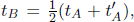 they can conclude that the clocks are synchronized. Otherwise, the poor engineers then have to go back to tweaking the readings of the clocks until this condition is eventually fulfilled! This process can be repeated for all pairs of clocks in an inertial frame to synchronize them.
Now that we have synchronized clocks that are operating in all space in a certain frame (it doesn’t matter how this is achieved as long as the clocks are synchronized), whenever an event transpires at a position in that frame, its time of occurrence in that frame can be defined to be the recorded reading of the clock (of that frame) at that particular point in space. The time when the clocks were started can be used as a temporal reference point in this case. Accordingly, the time difference between two events in a frame is simply the difference between the times recorded by the clocks of that frame at the corresponding positions.
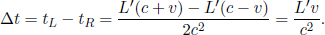
When there are multiple inertial frames, an array of synchronized clocks can be defined for each frame in general. These arrays may or may not be identical. In fact, we will discover that they are vastly different in the following sections due to the ramifications of the postulates. Figure 11.1 depicts two arrays of clocks synchronized with respect to two inertial frames, S and S’, with conventional definitions. Note that the clocks in frame S appear like the following with respect to frame S. An observer in frame S’ may or may not observe clocks in frame S to be the same as that observed by an observer in frame S. The reverse is also true.

Figure 11.1:Two arrays of clocks viewed in their own frames
Finally, a core aspect of special relativity is the grounding of time on a firmer observable foundation. Time is no longer an abstract concept that is independent of physical processes. It is necessarily measured by physical systems such as sandglasses and oscillating pendulums. Therefore, since an event requires a time of occurrence in order to be defined, the observation of the same event in different inertial frames can conversely be used to relate the times in different frames (e.g. in S and S’). This will be a key component of the following section. To this end, keep in mind that the time of an event, as recorded by a clock, must be independent of the frame that we observe the same clock3 from (we need not only observe it from its rest frame). However, the process through which the reading on the clock undergoes in attaining the final coherent reading may differ across inertial frames.
As a consequence of the postulates, events that are simultaneous in one inertial frame are not simultaneous in another! Then, clocks that are synchronized in one inertial frame of reference are not synchronized in another!
Consider the following situation: observer A sits on a train that is traveling at a speed v towards the right in observer B’s frame. Similarly, A observes B to move towards the left at a speed v. Subsequently, A observes lightning to simultaneously strike the opposite ends of the train in his own frame. However, observer B will conclude that the lightning does not synchronously strike both ends of the train in his frame, as we shall see!
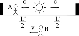
Figure 11.2:Observer A’s frame
Referring to Fig. 11.2, we can imagine placing a light source at the center of the train, that is stationary relative to the train. The light source then emits two photons towards the two ends of the train. We define the times of these emissions to be zero in both observers’ frames. Then, we can define the times of occurrence of the lightning strikes in a particular frame to be those when the corresponding photons collide with the walls of the train in that frame. It does not matter if there isn’t an actual light source in the set-up. What matters is that we could have placed one if we wanted to and used it as a temporal yardstick to “call lightning to strike upon a wall” when that wall receives a photon. Thus, the following analysis is valid regardless of whether an actual physical light source is used.
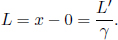
In the frame of A, the train is not moving and if we define the train to be of length L′, the photons will strike the ends of the wall in time

simultaneously in A’s frame (this is the reason why we placed the light source in the middle of the train). Now consider the frame of B in Fig. 11.3, both walls of the train move towards the right at speed v.
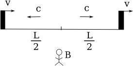
Figure 11.3:Observer B’s frame
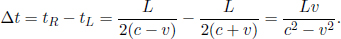
As the speed of light remains at a constant value c in B’s frame of reference, the times taken for the photons to reach the left and right ends of the train are respectively
where L is the length of the train in B’s frame. L may or may not be equal to L′ (we can’t be certain right now as the postulates did not state so). We see that these two events are in fact not simultaneous with respect to B’s frame of reference as long as v ≠ 0. In fact,
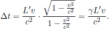
It turns out that L is indeed different from L′. We shall just invoke the result from a later argument that

where

Thus,
This is a solemn admonishment that events that we consider simultaneous in one inertial frame are not simultaneous in another. We should always take care in identifying the frame that is currently under consideration. It makes no sense to say that two events occur concurrently without explicitly mentioning the inertial frame of observation.
Now, let A’s frame be S’ and B’s frame be S, under the standard configuration. Define the origins O’ and O to coincide at t′ = t = 0 at the instantaneous location of the left end of the train. Attach two clocks, synchronized in S’, to the left and right ends of the train and consider two clocks, synchronized and stationary in S (i.e. these clocks do not move with the train but rest on the ground), that coincide with the instantaneous locations of the ends of the train at t′ = 0. If the left and right clocks of S’ (by clocks of a frame, we mean clocks synchronized in that frame) record  when lightning strikes the two ends of the train, we know from the previous scenario that the right clock of S will indicate a reading
  while the left clock of S will record tL = 0 (as the left clocks of S and S’ are synchronized under the standard configuration). From B’s perspective, he would simply claim that the lightning struck the clocks of S at different junctures — resulting in the discrepancy in readings. However, A must also be able to explain the readings of the clocks synchronized in S (as the readings are physical events4 that should be immutable across inertial frames) so it is interesting to consider his perspective. Since A observes the two lightning events to occur simultaneously, the clocks of S must have been observed by A to have differing readings in the first place! That is, A observes clocks that are synchronized in S to be asynchronous! Thus, A explains the loss of simultaneity of two concurrent events in S’, as observed by B in S, as follows: since the clocks in B were asynchronous in the first place, they will naturally have a discrepancy in readings when lightning strikes them at the same instance in my frame!
In retrospect, it is rather intuitive that the above argument leads to the conclusion that clocks synchronized in one frame are not synchronized when observed in another frame as our train set-up is reminiscent of a particular method of synchronizing two clocks (putting a light source at the center) of a single frame.
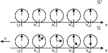
Figure 11.4:Clocks in corresponding positions in S as viewed by observer A in S’
To illustrate what A observes at t′ = 0, consider Fig. 11.4 which comprises an array of clocks synchronized in each of S’ and S. The clocks in S’ are stationary in S’ while the clocks in S are moving towards the left at speed v. At t′ = 0, the clocks in S’ coincide with the corresponding clocks in S (i.e.  at t′ = 0 corresponds to a clock at x-coordinate5 x1 with respect to the x-axis in S). The clocks at the origins O and O′ are synchronized such that t = t′ = 0 there. When A observes the clocks of S’ to read t′ = 0, the clock of S that corresponds to the x’-coordinate x′ reads
  such that the reading of the clocks of S increases towards the right as observed by A. A neat way of identifying the direction of increase is to remember that the rear clock is ahead (rear with respect to the velocity of the clocks). In summary, a moving array of clocks — synchronized in their common rest frame — is observed to possess a positive “gradient” in readings opposite to the direction of their velocities. Now, we have only established this result for t′ = 0 (i.e. a certain juncture in S’) and are unsure about other values of t′. It turns out, from the later section on time dilation, that the clocks of S tick at the same rate (as they are multiplied by the same dilation factor), as observed by A, so the “gradient” is maintained at all times t′.
As a word of caution for those who have had some exposure to time dilation, be wary that this result is not implying that the rear clock in frame S ticks at a faster rate than the front clock with respect to an observer in frame S’. They actually tick at the same rate as viewed by an observer in frame S’ but the rear clock in frame S is simply a constant time ahead of the front clock, as observed by A in S’, because the clocks are asynchronous as observed by A.
Simultaneous Events with Respect to Observer B
Now consider the previous situation again, except that this time, lightning strikes the ends of the train simultaneously in B’s frame. How will the timings of the two lightning strikes differ in A’s frame if the length of the train in A’s frame is L′?
Similarly, imagine placing a light source which emits two photons in opposite directions on the train. We shall denote the time of a lightning strike at a wall in a frame to be that when a photon hits that wall. In order for the photons to strike the walls concurrently in B’s frame, we know from the previous analysis that the light source must divide the train into sections of ratio c + v : c – v in B’s frame. This ratio must also hold in A’s frame.6 Thus, the set-up looks like Fig. 11.5 in A’s frame.
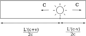
Figure 11.5:Light source in train with respect to A’s frame
The time taken by the left photon to hit the left wall is longer than that required by the right photon to collide with the right wall in A’s frame by
Formally, if we define observer A’s and B’s frames to be S’ and S respectively and their positive axes, x’ and x, to be along the direction of the train’s velocity in frame S, B will observe the reading of the rear clock in frame S’ to lead that of the front clock by time  where L′ is the difference in the x’-coordinates of the two clocks in frame S’.
In order words, spatially separated events that are deemed by B to be simultaneous are events that differ by a time of  in frame S’. Specifically, the spatially leading event must lag behind the spatially trailing event by in frame S’ in order for them to be simultaneous in frame S.7
To visualize this from the perspective of B, assume that the clocks at the origins of S and S’, O and O′, are synchronized when they coincide such that t = t′ = 0 at that juncture.
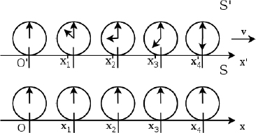
Figure 11.6:Clocks in S’ as viewed by observer B in S
At t = 0, if the x’-coordinate of a clock of S’ is x′, its reading will be  as observed by B. In Fig. 11.6, all clocks of S’ — except that at O′ — are displaying negative times as the reading of the clock at O′ — which leads the other clocks — is zero. Finally, we comment on an aside for readers who are interested in the x-coordinate x that corresponds to x’-coordinate x′ at t = 0. Since x′ is akin to the length of a train in its own rest frame while x is the observed length of the moving train in another frame, we can deduce that
  from the equation
  that we have used earlier. It remains for the reader to check if the two time discrepancies for simultaneous events with respect to A and with respect to B are coherent.8
The crux of the relativity of simultaneity is that observers in different inertial frames have different planes of simultaneity and hence observe different sets of present events. Roger Penrose proposed an argument that magnifies this effect to the extent of bizarreness.
Consider two twins that are situated at the same place on Earth, one walks in a direction towards the Andromeda galaxy while the other walks in the opposite direction. The twin that walks towards the Andromeda galaxy observes aliens traveling on spaceships en route to invade the Earth as the clock on the Andromeda galaxy is the rear clock in his frame. Thus, this twin observes events on the Andromeda galaxy to unfold much earlier than a stationary observer on the Earth. On the other hand, the other twin observes aliens convening a meeting to decide whether they should attack the meddlesome humans. This is because the Earth is now the rear clock relative to this twin. Thus, this twin will observe events at Andromeda that have already occurred in the frame of a stationary observer on Earth.
There is an apparent paradox here. How can there still be a hint of uncertainty of an alien invasion as observed by one twin while the other concludes that an imminent attack is inevitable? Before we resolve this apparent paradox, there is a clear distinction to be made between “seeing” and “observing” an event. Each twin “observes” an event on Andromeda that occurs concurrently with the present in their own inertial frame. However, he or she does not “see” that event yet as it takes time for information or photons to travel towards his or her location as the transmission of information cannot be faster than the speed of light in vacuum, c.
Well, there are usually two types of paradoxes in special relativity — those that result from fallacious reasoning and those whose consequences are so counter-intuitive that we reject them in disbelief. The situation above happens to fall into the latter category. They indeed make those observations without any contradiction. Thankfully or unfortunately, logical consistency is still maintained as it takes time for the information to reach the two twins. Suppose that the observed distance between the Earth and the Andromeda galaxy by the “prophetic” twin is L′ and v is the relative velocity between him and Andromeda galaxy. The minimum time that it takes for information from the Andromeda galaxy to travel to him (assuming that information travels at the theoretically maximum speed of light) is

which is greater that the  “time lead into the future”. Thus, the twin who “observes the future” is unable to change the fate of his planet as he is unable to “see the future” in time.
The time interval between spatially coincident events in frame S’, as measured by an observer in S, is larger than that as measured by an observer in S’. A direct ramification of this is that a clock that is moving with respect to an observer will be observed to run slower in that observer’s frame. Consider the set-up in Fig. 11.7: observer A is in a train traveling at a speed v towards the right relative to observer B. From A’s perspective, a stationary light source emits a vertical beam that is reflected normally by a mirror attached to the ceiling of the train.

Figure 11.7:Time dilation set-up
The time taken by the light during its roundabout trip in A’s frame is simply

However, from B’s perspective, the situation is shown in Fig. 11.8: the light has a component of velocity in the horizontal direction as the train is moving towards the right. However, the speed of light must still be maintained at c in B’s frame.

Figure 11.8:Situation in B’s frame
The journey in B’s frame takes
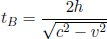
where we have applied Pythagoras’ theorem in calculating the vertical component of the velocity of light.9 We realize that

where

This γ factor is ubiquitous in special relativity and thus deserves a special symbol on its own for simplicity. We see that gamma is always greater or equal to unity. Now, the above result means that B observes the time interval between two events that occur at the same spatial position in A’s frame to be larger than that measured by A. Note that the only spatial position of concern is along the direction of the relative velocity between the two frames (as the result holds as long as light can traverse a straight path perpendicular to v in A’s frame). In this case, it is the horizontal direction. The time dilation result still applies to the time difference between two events that are of the same horizontal position but different vertical positions in A’s frame (e.g. the time elapsed between the release of the beam and its incidence on the mirror).
It is paramount for the events under consideration to be at the same spatial coordinate of concern in A’s frame in order for the time dilation equation above to be valid. If the two events are not at the same spatial coordinate in A’s frame, there needs to be an additional correction for the loss of simultaneity of the clocks, synchronized in A’s frame, as observed by B. Thus, the time dilation equation cannot be directly applied in this case.
Now, what does time dilation imply for the operation of clocks? The release and the receiving events of the light beam are analogous to the beginning and end of a clock-tick on A’s “light clock.” Then, B observes A’s clock to tick at a slower rate than that observed by A, as the time interval between successive ticks is longer. As always, keep in mind that this statement is independent of whether a physical “light clock” is actually used. The point is that we could have used it to measure time if we wanted to.
Now, one may ask if time dilation actually happens in B’s frame or is simply perceived to happen. The answer is that time dilation actually occurs in B’s frame. If  and A’s heart beats every 2 seconds as observed by himself (these pulsating events occur at the same location in A’s frame), B will observe A’s heart to beat every 3 seconds. Equivalently, it means that from B’s perspective, the transition between two events that are spatially coincident in A’s frame plays in slow motion. Therefore, B will actually observe A to age slower than he does as biological processes, too, slow down.

Figure 11.9:Clocks after 15 seconds have passed in frame S
To visualize time dilation, consider the set-up in Fig. 11.9 with γ = 2. At time t = 0 in frame S, the one-minute clocks in frame S’ are asynchronous with respect to an observer in S due to the loss of simultaneity. Note that the four clocks on the right of O’ all measure a negative reading as the rear clock — which is the clock at O’ in frame S’ in this case — leads the front clocks. However, the clocks at the origin are synchronized such that t = t′ = 0 when the origins O and O’ coincide. After 15 seconds have passed in frame S such that t = 15s, only a time interval Δt′ = 7.5s has passed in frame S’ as observed in S. Thus the readings on the clocks10 in frame S’ only increase by 7.5s, as tracked by an observer in S.
Apparent Paradox: Now you might argue that from A’s frame, B’s clock also seems to run slower. There is an apparent paradox, as we seem to be asserting that A’s clock ticks at a slower rate than B’s but also that B’s clock ticks at a slower rate than A’s. How is this possible?
The above is indeed true — as long as we define the inertial frame we are considering. In A’s frame, B’s clock runs slower while in B’s frame, A’s clock runs slower. There is no contradiction here as these are different events. One is the tick of B’s clock and the other is the tick of A’s. Let us consider the clock-tick of A’s clock as an example. In A’s frame, the start and end of the clock-tick trivially occur at the same position. Thus, we can say that tB = γtA where tA and tB are the times between consecutive ticks of A’s clock in the frames of A and B respectively. However, the clock-ticks of A obviously do not happen at the same position in B’s frame. Thus, we cannot conclude that tA = γtB. We can only say so if tA and tB refer to the times between the ticks of B’s clock in A and B’s frames respectively. To illustrate this, we refer to the previous diagram. Suppose that we now consider the frame of S’ such that the clocks of S are traveling towards the left at speed v. If γ = 2 and Δt′ = 15s passes in S’, an observer in S’ will only observe the readings of the clocks of S to increase by 7.5s too (note that you need to account for the loss of simultaneity if you want to talk about the exact readings).
The final piece of the puzzle concerns how moving objects are observed to be shortened longitudinally, parallel to their direction of motion. Consider the situation in Fig. 11.10. There are two twins, A and B, that are on the Earth. Twin A rapidly travels to the Moon at a speed v relative to twin B who remains on the Earth. The Moon is a distance L from the Earth as observed by twin B.
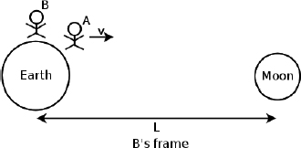
Figure 11.10:Twin A traveling to the Moon in B’s frame
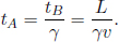
The time taken for twin A to reach the Moon in B’s inertial frame is simply

Now, notice that the starting and ending events in B’s frame occur at different spatial locations. Therefore, tB is really calculated by taking the difference in the readings of two synchronized clocks, one in B’s hands that measures A’s deparature and one on the Moon that measures A’s arrival, in B’s frame. Moving on, we know from the previous section that moving clocks run slower. Thus, during this period of time, a clock held by twin A measures a reading of
In A’s inertial frame, the situation is depicted in Fig. 11.11: the Moon is now traveling towards A.
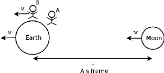
Figure 11.11:Twin A’s frame
Since A’s clock records a reading of  after the entire process and the Moon travels at speed v, the distance between the Earth and the Moon as observed by twin A is
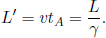
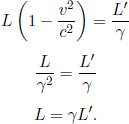
Thus, the distance between the Earth and the Moon must have shrunk by a factor of  in A’s frame. The observed distance between the Earth and the Moon is analogous to the observed length of an object with its ends defined to be the Earth and the Moon. Generally, if an object has a length L in its own inertial frame (rest frame), a stationary observer in another frame will observe that same object to have length
  if the object travels at a longitudinal speed v relative to this new frame. Furthermore, length contraction is independent of the position on an object — all parts of the object are shortened by the same proportion (see Footnote 6). On another note, since the longitudinal length of an object is dependent on the inertial frame of reference, the proper length of an object is defined to be the length measured in its own rest frame (i.e. the object is stationary in that inertial frame).
Length contraction does not occur in the transverse direction. This can be proven by a simple argument that relies on the fact that physical consequences must be coherent across inertial frames, though measurements may differ. Consider a truck of proper height L traveling at a speed v into a tunnel of identical proper height L. If length contraction occurred in the transverse direction, the truck will observe the tunnel to be shortened in its inertial frame. Then in the truck’s frame, the truck will crash into the tunnel. However, in the inertial frame of the tunnel, the truck is shortened and the truck passes scot-free. Evidently, there is a contradiction here. A similar argument can be used to prove that the transverse length of a moving object does not increase either. Thus, the transverse length of an object must be identical across different inertial frames.
What does Measuring Length Really Mean?
To establish a rigorous meaning for measuring length, let us return to the case of measuring the length of an object in a high school physics laboratory. We take a ruler11 and record the readings of the ends of the object of concern via the markings on the ruler. Then, the length of the object can be obtained by taking the difference of these two readings. Now, an important qualification needs to be made here. The two readings need to be made at the same time. If our object were to move at a certain velocity relative to us (which is certainly possible), it makes no sense to jot down the coordinates of its ends at different times. In light of this discussion, the distance between two events, as observed in a frame S, is the difference in their spatial coordinates when they are observed simultaneously. This understanding is crucial in analyzing many situations.
For example, an intriguing question to ask is how A convinces himself that if his observed distance between the Earth and the Moon is L′, the distance observed by B must be L = γL′ from the model of clocks and meter sticks. Denote A’s frame as S’ and B’s frame as S. Suppose that we attach two clocks synchronized in S to the Earth and Moon.
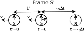
Figure 11.12:Clocks synchronized in S, as observed in S’
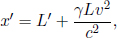
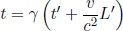
Referring to Fig. 11.12, if A measures the distance between the Earth and the Moon to be L′ at time t′ = 0 and if the clock of S on the Earth reads t = 0 at this juncture, the rear clock (on the Moon) must have a reading 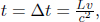 as spatially separated events that are simultaneous in S’ are those that are a time interval
  apart in S (where L is the spatial separation between the events in S). Now, A knows that B must measure the distance between these clocks at the same time t in S, such as when both clocks display t = 0. Therefore, A can retain the position of the left clock (which already displays t = 0 at t′ = 0), while considering the position of the right clock at t′ =
  (dotted in Fig. 11.12) such that the right clock reads t = 0. Note that we have multiplied by a factor of γ as the ticking of the clock of S slows down by a factor of γ due to time dilation. Observer A measures the spatial separation between the left and right clocks at these specific junctures to be
so he can reason that the distance between these events (which are now simultaneous in S and hence reflect the distance between the Earth and Moon) will be observed by B to be
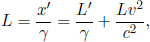
as A understands that meter sticks (which form the spatial coordinate axes of S’) attached to his frame are shrunk by a factor of γ (because they are moving in frame S) such that the separation in x’-coordinates of two events simultaneous in S is amplified by a factor of γ as compared to the corresponding separation in x-coordinates. Solving,
Incidentally, a pivotal concept is revealed in the analysis above. In measuring the lengths of objects by different observers (e.g. A and B), the pairs of events that are considered differ across observers, as a set of events simultaneous in one frame is asynchronous in another. Referring to the set-up that we have just dissected, even though both observers consider the clock on the Earth when it reads t = t′ = 0, A uses the clock of S on the Moon when it reads  (corresponding to t′ = 0) while B uses the clock on the Moon when it reads t = 0 in determining their observed distances between the Earth and the Moon.
Problem: In the previous set-up, it is known that B’s clock reads  during the entire journey, where L is the distance between Earth and the Moon as observed by A. In B’s frame, how does B reason that his journey took
  time in A’s frame? That is, how do the relevant clocks of A’s frame play out in B’s frame?
B syncs his clock with A on Earth. The time of the starting event as measured by A is thus zero. The duration of B’s journey in A’s frame is then simply the reading of the clock on the Moon. In B’s frame, the clock on the Moon is ahead of A’s clock by  as it is the rear clock. Furthermore, in B’s frame, the time elapsed on his clock is . Therefore, the time elapsed on the Moon’s clock during B’s journey, as observed by B, is
  by time dilation. The final reading on the Moon’s clock is
By now, you may have realized that our model of the arrays of clocks and meter sticks is becoming extremely complicated. It is intuitive to extend this crude model by replacing the clocks synchronized in a frame with a unified time axis, which adds a fourth dimension to our analysis. Then, we can obtain a diagram with space-time as its fabric, which is commonly known as a Minkowski diagram. Usually, it is more convenient to use ct as the time axis as opposed to t. The speed of light, c, is then similar to a conversion factor between space and time. Let us draw a space-time diagram of ct against x of an arbitrary frame S in Fig. 11.13 and superimpose part of the original model of clocks on it.
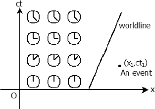
Figure 11.13:Minkowski diagram with superimposed clocks
The array of clocks in this frame is synchronized so that they all record a reading of zero at t = 0 in this frame. Now imagine a vertical line, x = k, on the space-time diagram. This line corresponds to the space-time states of a stationary clock at coordinate k in frame S as time passes. Basically, the clock is motionless and its reading just increases at a constant rate as time elapses. The reading on the clock at a point on that line increases with the height of the vertical position of that point.
An event corresponds to a point on the space-time diagram. It has a position as indicated by its x-coordinate and a time of occurrence that is implied by its ct-coordinate. This ct-coordinate is essentially the reading on a clock (times c) that is placed at the event’s spatial location when the event transpires.
Lastly, a world line of an object is the set of points x(t) that corresponds to the path of the object on the space-time diagram as time elapses. For an object that is moving at a constant velocity with respect to the current inertial frame, its world line is a straight line on the space-time diagram. The world line of a photon is always a 45° line, regardless of the inertial frame of reference, due to the constancy of the speed of light. Note that the instantaneous gradient at all points on all possible world lines must have an angle12 of inclination greater or equal to 45° as no matter or information can travel at a speed greater than the speed of light in a vacuum.
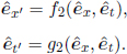
Generally, we are interested in the coordinates of certain events in an inertial frame and how they vary across different frames. When switching between inertial frames, we are essentially transforming the coordinates of a point or a set of points into those of a new inertial frame. Generally, there are two views of the transformation of coordinates. An active transformation shifts the set of points of concern into new positions on the original axes and then replaces the x and ct-axes with the new axes x’ and ct’. It is obtained by transforming the coordinates of an event in frame S into that in frame S′ directly.

where f1(x, ct) and g1(x, ct) are the appropriate transformation functions. A passive transformation modifies the axes while leaving the set of points unchanged. Then, the coordinates of the points are read off the new axes x’ and ct’. If we define 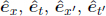 to be unit vectors along the x, ct, x’ and ct’-axes respectively (also known as the basis vectors), the transformation is obtained by performing
Moving on, the transformation of coordinates from one inertial frame to another must be linear as a consequence of the homogeneity of space and time in inertial frames. Suppose two events occur at coordinates x1 and x2 in frame S at the same time t. Then let

be the x’-coordinates of the events in the new inertial frame S’. Then, the spatial separation of these events in frame S’ is

Next, by the homogeneity of space in inertial frames, if we modify our original coordinate system by a simple translation in the x-direction such that x1 and x2 become x1 + k and x2 + k for some constant k, their spatial separation in S’ should still be l, as it is a tangible, spatial separation between two events. Then,
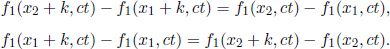
Dividing the above equation by k and taking the limit as k → 0,
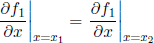
from the first principles of calculus. Since x1 and x2 are arbitrary, this means that

for some constant α which implies that f1 is linear in x. A similar argument can be invoked to show that f1 in linear in t by the homogeneity of time (by considering a translation in time). Lastly, similar arguments also be used to prove that g1 is linear in x and t as well (by considering a temporal separation in S’). Then,
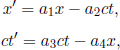
for some constants a1, a2, a3 and a4, as each transformation should be linear in x and t. We shall derive these constants in the next section.
Instead of having to repeat the error-prone process of accounting for the relativity of simultaneity, time dilation and length contraction effects, it is much more desirable to have an integrated transformation procedure. The Lorentz transformations empower us with the ability to algebraically calculate the coordinates of an event in a new inertial frame, given its coordinates in a previous inertial frame and the relative velocity between the two frames. Formally, the spatial and temporal separation between two events in frame S as a function of those in frame S’, which is moving at a velocity v with respect to the x-axis in frame S, is given by
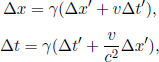
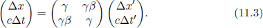
where Δx′ and Δt′ are the spatial and temporal separations of two events in frame S’ while Δx and Δt are those in frame S. These equations can be written in a more convenient and symmetric form


where  They can be expressed even more compactly with the use of matrices:
The inverse transformations from frame S to frame S’ are obtained from substituting –v for v.


or
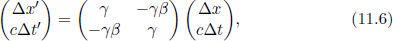
with the same definitions of v and γ.
The above transformations can be proven by employing the relativistic effects that we have derived before and the linearity of the transformations between inertial frames. This can be visualized better by considering spacetime diagrams undergoing an active transformation. Consider two inertial frames S and S’. S’ is moving at a velocity v relative to S along the positive x-axis of S. As only the separation between two events are of interest, coordinate systems in the inertial frames can be chosen such that one of the events are at the origins, O and O’, in both of the inertial frames S and S’. This is due to the invariance of the separation between two events when the coordinate systems undergo a translation — a consequence of the homogeneity of inertial frames.
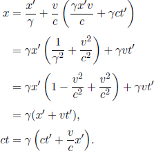
Following from this, two events, P and Q, occur at the origin O’ and point (x′, ct′) on the space-time diagram in frame S’. We wish to find the coordinates of Q on the space-time diagram in frame S. Event P is again located at the origin of the space-time diagram in frame S, O.
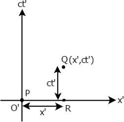
Figure 11.14:Events P, Q and R in frame S’
Referring to Fig. 11.14, consider another point R at coordinates (x′, 0) in frame S’. Physically, it may represent a clock that is at coordinate x′ and synchronized with the clock at the origin, O′. The world line of a clock at coordinate x′ passes through the point Q in frame S’. Now, consider the same situation in frame S. In frame S, objects that are stationary in S’ now travel at a velocity v. Thus, the space-time diagram for frame S is illustrated by Fig. 11.15.
The two world lines are those of the two stationary clocks at x’-coordinates 0 and x′ when viewed in frame S’. We know that the slope of the world lines of the two clocks are  Furthermore, point Q must still lie on the world line of the clock at R in frame S as it did so in frame S’. The distance between these world lines that is measured at the same time t in frame S is
  due to length contraction. Furthermore, it is known from the relativity of simultaneity that two clocks that are synchronous and separated by a distance of x′ in frame S’ differ by a time
  in frame S. Applied to the situation at hand, the two clocks are those at P and R respectively. Moreover, the time interval between two events that are at the same x’-coordinate in frame S’ is observed to be time-dilated in frame S. The two events in this case refer to Q and R (the readings of the clock at x′) which differ by a time interval γct′ in frame S. These effects are labeled appropriately in the diagram above.
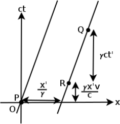
Figure 11.15:Fundamental effects and events in frame S
Combining the information obtained from these effects, the coordinates of Q in this frame can then be easily found.
The inverse transformations from frame S to frame S’ can then be obtained by substituting –v for v in the equations above, as frame S travels at ′v relative to the positive x’-axis of frame S’, the primed coordinates for the unprimed ones and vice-versa.

Note that the spatial separations of two events along directions that are perpendicular to the x-direction are unchanged across inertial frames.

as there is no loss of simultaneity (use a similar set-up involving light in a train) nor length contraction in the transverse direction.
Finally, let us obtain some form of closure by showing how the Lorentz transformations can be intuitively understood by our previous model of clocks and meter sticks.
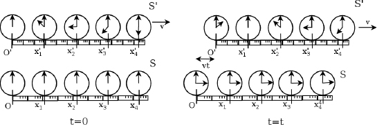
Figure 11.16:Clocks and meter sticks of S’ (top) and S (bottom) as observed in S
At time t = 0 in frame S, the origins of the two coordinate systems of S’ and S are aligned in Fig. 11.16. At this juncture, a clock of S that is at x-coordinate x coincides (in terms of location) with a clock of S’ that is at x’-coordinate x′ = γx (x′ is scaled by a factor of γ as the meter sticks of S’ are shrunk by a factor of γ). However, a clock synchronized in frame S’, that is located at x’-coordinate x′, is observed in frame S’ to possess a reading  due to the relativity of simultaneity.
At time t in frame S, origin O’ of S’ would have traveled towards the right, relative to O, by a distance vt. Therefore, a clock of S that is at x-coordinate x now coincides (in terms of location) with a clock of S’ that is at x’-coordinate x′ = γ(x – vt). We immediately obtain the first transformation rule
Next, since time t has passed in frame S, the readings of the clocks of S’ would have increased by  (reduced by a factor of
  as the clocks of S’ tick slower due to time dilation). Therefore, a clock of S at x-coordinate x and time t corresponds to a clock of S’ at x-coordinate x′ which displays a time
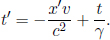
Substituting the expression for x′,
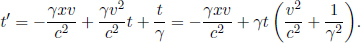
Plugging in  we retrieve the second transformation rule.

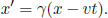
Problem: Derive the length contraction result from the Lorentz transformations.
Let the longitudinal proper length of an object be L′ in its rest frame S’. Define the origin in S’ such that the left and right ends of the object are located at x′ = 0 and x′ = L′ respectively (at all times t′). Now, suppose that we are interested in determining the length of this object in a frame S that travels at a velocity –v in the x’-direction relative to S’. To do so, we need to determine the spatial separation of the two ends of the object simultaneously in S. Presuming that we want to do this when t = 0 in S, the left end is at x = 0 (since the origins of S and S’ coincide at t = t′ = 0). Now, we just need to determine the x-coordinate of the right end at t = 0. Notice that the (x′, ct–) coordinates of the right end in S’ are generally (L′, ct–). Applying the Lorentz transformations, the time of this event in frame S is
so we must choose to observe the right end at  in S’, as it corresponds to t = 0 in S. Applying the Lorentz transformations to
  in S’, the x-coordinate of the right end at t = 0 in S is then
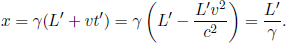
The spatial separation of the two ends of the object at t = 0 (which is the observed length in S) is
Remember that there is an alternate perspective to the transformation of coordinates. Instead of modifying the position of the points, the axes can be changed. In this section, we will consider the passive transformation from frame S to frame S’. It is then natural to determine how the new axes, x’ and ct’ of frame S’ will look like when superimposed on the space-time diagram of frame S with x and ct as its axes.
Even without any calculations, it can be concluded that these x’ and ct’-axes must be straight lines on the space-time diagram in frame S as the Lorentz transformations are linear. Thus, straight lines must be mapped onto straight lines. Assume that the origins of the two coordinate systems in the two inertial frames coincide. The equation of the x’-axis can be determined by using the fact that t′ = 0 along it. Then, by the Lorentz transformations,

Similarly, along the t’-axis, X′ = 0.
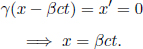
These are the equations of the lines on the Minkowski diagram of frame S that delineate the x’ and ct’-axes respectively. They are plotted on the space-time diagram in frame S in Fig. 11.17.
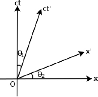
Figure 11.17:Superimposed x’ and ct’-axes on Minkowski diagram in frame S
By considering the line equations above, it can easily be proven that the two angles labeled in the figure obey the relation

Observe that the superimposed x’ and ct’-axes are not mutually perpendicular. Orthogonal vectors in one inertial frame need not be perpendicular in another. Lines on the space-time diagram that are parallel to the superimposed x’ and ct’-axes are sets of events that are simultaneous and occur at the same x’-coordinate in frame S’ respectively.
The relativity of simultaneity can be easily visualized with the superimposed x’ and ct’-axes. Consider Figs. 11.18 and 11.19.
Figure 11.18:Clocks synchronized in frame S

Figure 11.19:Clocks synchronized in frame S′
In both diagrams, the horizontal and slanted lines represent the lines of simultaneity in frames S and S’ in the Minkowski diagram of frame S respectively. The array of clocks on the left is synchronized in frame S. It can be seen that the events that are simultaneous in frame S, represented by horizontal lines, are not simultaneous in frame S’ whose lines of simultaneity are represented by the slanted lines (parallel to the overlapping x’-axis). An observer in S’ that observes certain clocks of S simultaneously will conclude that the readings on the clocks are asynchronous (consider the clocks along any slanted dotted line as an example). Similarly, the array of clocks on the right is synchronized in frame S’. Conversely, an observer in S that observes certain clocks of S’ simultaneously will conclude that the readings on the clocks are asynchronous. It is natural for an observer in either frame to conclude that the clocks in the other’s frame are asynchronous — a fact that is evident from the asymmetrical lines of simultaneity.
To complete our analysis of the superimposed axes, we need to find how the magnitude of one unit along the x’ and ct’-axes in frame S’ is reflected on the x’ and ct’-axes that are superimposed on the space-time diagram of frame S. There is a need to do so as the coordinates are now measured with respect to the x and ct-axes (i.e. there is no guarantee that they will be the same). Consider the point (1, 0) in frame S’; the first and second coordinates correspond to the x’ and ct’-coordinates respectively. Thus by the Lorentz transformations, the coordinates of this point in frame S is (γ, γβ). This signifies that one unit along the x’-axis in frame S’ corresponds to

units of length as measured by the x and ct-axes in the space-time diagram in frame S. In other words, a point with coordinates (x′, 0) in frame S’ will be a length along the superimposed x’-axis in frame S as measured by the x- and ct-axes. Similarly, a point (0, 1) in frame S’ will transform to a point (γβ, γ). Thus, one unit along the ct’-axis in frame S’ also corresponds to
units of length as measured by the x and ct-axes in the space-time diagram in frame S. Following from this, the x’ and ct’-coordinates of an event can be deduced by drawing lines that pass through that event and are parallel to the superimposed ct’ and x’-axes in the Minkowski diagram of frame S respectively. Afterwards, one can identify the points of intersection of these two lines with the superimposed x’ and ct’-axes and divide the distances between these points of intersection and the origin by the scaling factor  to obtain the x’ and ct’-coordinates of the event in frame S’.
The Twins’ Paradox
Problem: Consider two twins, A and B, who are initially on Earth. In Fig. 11.20, twin B remains on Earth while twin A travels on a rocket to a distant star at a constant speed v relative to B’s frame and back to Earth at a constant speed v, in the opposite direction, rapidly. When the two twins eventually compare the readings on their clocks, which twin is younger?
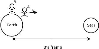
Figure 11.20:A’s outbound journey in the frame of B
Let the frame of twin A be S’ and that of twin B be S. There is an apparent paradox here. In frame S, twin B sees twin A’s clock running slower by a factor of  Thus, B will conclude that A is younger. However in frame S’, twin A also sees twin B’s clock running slow. Thus, A will seemingly also conclude that B is younger. There appears to be a paradox here as the readings on both clocks must be the same, as observed by the twins, when they are compared at the same location. However, the correct answer is, in fact, that twin A is younger!
This is because the symmetry in this system is broken when twin A reverses the direction of his velocity, as he must experience an acceleration then. In other words, twin A is actually stationary in two different inertial frames during his outbound and inbound journeys. Thus, the above reasoning in frame S’ is invalid as there are really two different inertial frames of A. However, this reasoning only explains why the latter analysis in A’s frame is wrong but does not show how to correct that reasoning. There are many ways of resolving this. One argument will be presented here. Let us first consider the situation in frame S. Let the distance between the distant star and Earth in frame S be L. Then, the time of the entire journey by A in S is

The elapsed time of the entire journey in A’s two inertial frames is then

as B observes A’s clock to slow down by a factor of . Therefore, B will conclude that A is younger than him by a factor of . Next, we would like to consider the situation from A’s perspective. This is better visualized by drawing a space-time diagram in frame S and superimposing the axes of A’s inertial frames, as there are in fact two inertial frames of A.
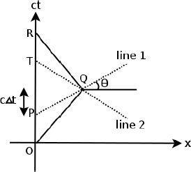
Figure 11.21:Minkowski diagram in B’s frame (S)
The line OQR in Fig. 11.21 represents the world line of twin A in frame S while the line OR is the world line of twin B whose stationary clock just ticks with time. The two inertial frames of A consist of one before the kink at point Q and one after the kink. Let the axes of the two inertial frames be x’, ct’ and x″, ct″ respectively. We know that the lines of simultaneity in those frames are represented by the lines parallel to the x’- and x”-axes. Consider the point Q at which twin A turns, causing him to switch from the first inertial frame to the second. This causes the line of simultaneity through point Q to instantaneously change from line 1 to line 2, which are parallel to the x’ and x”-axes respectively, as indicated on the diagram.
Since points on the line OR correspond to the readings of B’s clock, this physically means that twin A observes twin B to spontaneously age by a certain amount as he turns. Here lies the crux of this resolution. From A’s perspective, B instantaneously ages by the time interval between points T and P in frame S, which is equal to 2Δt as labeled on the diagram. Δt can be easily found by utilizing the facts that the spatial separation between P and Q is L and that tan θ = β.
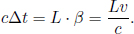
Thus,

This is the amount that twin B instantaneously ages as observed by A in his own frame when he turns around. Actually, this particular value can also be explained from the relativity of simultaneity. In A’s outbound journey, the star’s clock was the “rear clock” and thus led the Earth’s clock by  However, when A turned around, the Earth’s clock became the “rear clock” — leading to a total discontinuity
  of time. With this, the entire process from A’s perspective can be outlined as follows — we start with the reading of A’s clock. The distance between the Earth and the distant star is
  in both of A’s frames due to length contraction. Furthermore, twin A observes the distant star and Earth to approach him at a speed v in his first and second inertial frames respectively. Thus, the total time elapsed on A’s clock is

To investigate how the reading of B’s clock changes from the perspective of A, we divide the entire process into three parts — namely before the turn, during the turn and after the turn. The situation of the first part in A’s first frame appears in Fig. 11.22 — A observes both the Earth and the distant star to travel at speed v.

Figure 11.22:First half of the journey in A’s first inertial frame
This takes for the distant star to reach A in A’s frame due to length contraction. As twin A observes B’s clock to run slow by a factor of the time elapsed as measured by twin B’s clock during the first part of the process is

which corresponds to the distance between points O and P (divided by c). Next, when twin A turns around, he observes the reading of B’s clock to immediately increase by

due to the switching of inertial frames. Lastly, during twin A’s return journey, the reading of B’s clock increases by

by an argument similar to that for t1. Thus, the total time elapsed by twin B’s clock from the perspective of twin A is
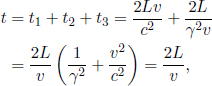
which is consistent with the result obtained by considering the set-up in B’s frame. Hence, twin A also concludes that he is younger than twin B by a factor of .
The interval Δs between two events in frame S is defined as

where the Δ’s represent the spatial and temporal separations between the two events. The interval Δs has a unique property — consider the right-hand side of the expression in a different inertial frame S’ that is moving at a velocity v with respect to frame S. By applying the Lorentz transformations,
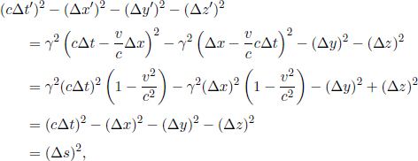
where we have used the fact that Δy = Δy′ and Δz = Δz′ as the y and z separations do not vary when switching between frames that travel with a relative velocity solely along the x-axis. It can be seen that the quantity (Δs)2 is invariant under the Lorentz transformations. The invariance of this quantity across various inertial frames is similar to the invariance of the squared distance between two points in an Euclidean space under rotations.

Therefore, the interval can be treated as the “squared distance” in Minkowski space. In fact, the Lorentz transformations are hyperbolic rotations of Minkowski space which makes the analogy even more apt. Now, three specific cases of the value of (Δs)2 between two events will be considered. In doing so, we align the x-axis of our coordinate system with the line joining the positions of the two events such that

for the sake of convenience.
Case 1: (Δs)2 < 0
Firstly, there is no need to worry that a squared term yields a negative value as Δs lacks physical meaning in itself and can be imaginary. In this situation, (Δx)2 > c2(Δt)2 and these events are said to be space-like separated. This means that there exists a frame S’ such that these two events occur at the same time t′. The Lorentz transformations give
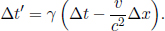
Therefore, there exists a velocity with magnitude less than the speed of light, specifically 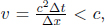 that leads to Δt′ = 0. However, these two events do not occur at the same x’-coordinate with respect to any inertial frame S’. This can be shown easily by contradiction. If Δx′ = 0,

where (Δs)2 < 0, leading to a contradiction as the right-hand side consists of physical quantities that must be real.
Lastly, it makes no sense to say whether event A occurs before or after event B when these two events are space-like separated. This is because there always exist inertial frames where A precedes B and where B precedes A. By the Lorentz transformations again,
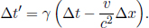
If Δt > 0, Δt′ < 0 when
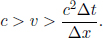
A similar argument can be made for the case where Δt < 0 to show that it is possible for Δt′ > 0. This proves that event A may precede event B in one inertial frame and that the reverse may be true in another. Concomitantly, these two events must not have a causality relationship (i.e. event A induces event B or vice-versa). If this were not the case, there will be a violation of causality as the relative order of A and B in time varies across different inertial frames.
Case 2: (Δs)2 = 0
In this situation, (Δx)2 = c2(Δt)2 and these events are said to be light-like separated. These events then correspond to the points of a photon’s path on a space-time diagram. It is impossible to find an inertial frame S’ in which the two events are simultaneous or occurs at the same x-coordinate as two points on the world line of an undisturbed photon cannot exist at different locations at the same time or at the same location at different times.
Case 3: (Δs)2 > 0
In this scenario, (Δx)2 < c2(Δt)2 and we say that these two events are timelike separated. Employing similar arguments as before, it can be proven that there exists an inertial frame S’ in which the two events occur at the same x’-coordinate while an inertial frame S’ in which the two events occur at the same time does not exist. If events A and B are time-like separated events and event A precedes B in a certain inertial frame, event A precedes B in all inertial frames. Therefore, it is possible for there to be a causality relationship between events A and B.
Proper Time and Proper Distance
Proper Time
The proper time, τ, of a point along a world line refers to the time measured by the clock which is perpetually at rest relative to the observer in the world line. Let us denote that observer as O. One can imagine observer O holding a clock that is constantly stationary to him or a fictitious time axis protruding from observer O. Then, O describes events with his own “local time”. The proper time interval between two events on the world line is then simply the time interval as observed by observer O in the world line.13 Evidently, these two events must be time-like separated in order for a proper world line to be defined. Furthermore, these two events must have the same spatial coordinates in the frame of observer O, as he is stationary. Now let observer O’s world line be r(t) with respect to a fixed inertial frame S. Consider an infinitesimal interval

where dx, dy, dz and dt are the infinitesimal spatial and temporal separations between two neighboring events along the world line of O with respect to the frame S. Since the interval is invariant, the infinitesimal proper time dT between these two events is given by
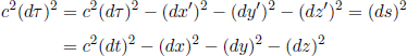
as the components of the spatial separation between any two events along the world line of O, as observed by O, are zero since O is stationary in his own frame (dx′ = dy′ = dz′ = 0). Then,
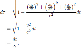
where v is the speed of observer O as observed in frame S. The proper time interval between two time-like separated events on O’s world line is then obtained from integrating the expression above.
If O is traveling at a constant speed, the integral can be performed trivially.

which is simply the time dilation equation. It is natural for us to obtain this result, as Δt simply means the time elapsed as measured by a still clock while Δt is that of a moving clock.
Proper Distance
The proper distance Δσ between two space-like separated events is defined as the distance between the two events, as observed in an inertial frame in which they are simultaneous. Since the interval between two events is invariant and because their temporal separation in that particular inertial frame is zero,

where the quantities on the right-hand side are measured with respect to an arbitrary frame S.
So far, we have asserted that no information or massive particle can travel faster than the speed of light in vacuum c. Some justifications shall be provided here. Firstly, consider the expression for σ
If |v| > c, γ is imaginary. Else if |v| = c, γ tends to infinity. This results in a loss in the physical meaning of our coordinate transformations and implies that these cases for |v| should be rejected.
The second argument pertains to the violation of causality. As shown before, if two events A and B are space-like separated such that  there exist inertial frames in which A precedes B and others in which B precedes A. This is perfectly fine in itself if these two events do not have a causality relationship mediated by physical entities or information. However, if there exists a particle or information that can travel at a velocity greater than the speed of light, it is possible for events A and B to be affected by one another due to the transmission of information via particles traveling at superluminal speeds. Then, these particles will be traveling back in time with respect to some inertial frames. Causality will be violated as the “effect” may precede the cause of an event in certain inertial frames. Here is an example. In an arbitrary frame S, observer A sends a superluminal signal to observer B. Immediately upon receiving the signal, observer B sends a superluminal signal back to observer A. This contravenes the causality relationship as there are inertial frames in which observer A receives the signal from B before he sends one himself (as the events are space-like separated)!
The last argument is relevant to the next chapter. As we shall see, it takes an infinite amount of energy for a particle with mass to travel at the speed of light — a feat that is physically infeasible.
In conclusion, the speed limit imposed by the speed of light is considered a corollary in special relativity. If this were to be breached, situations that are contrary to common experiences will arise. Therefore, it is widely accepted that neither information nor matter can travel at a speed greater than c.
Finally, there is a qualification to be made here, no matter or information can travel at a speed greater than c, the speed of light in vacuum. This is an important point to take note of as light propagates at different speeds in different media.
This section elaborates on the subsidiary effects due to the fundamental consequences of special relativity. We will adopt the conventional definitions for frames S and S’ and v. In approaching this section, remember that v refers to the relative velocity between frames while the symbol u (and u′) will be used to denote the velocity of a particle in a certain frame. Keep in mind that  and is independent of u, as it is associated with the transformation between frames.
Longitudinal Addition
If an observer in frame S’ observes a particle to travel at a velocity u′ in the direction of the x’-axis, what is the speed of the particle as observed by a person in frame S?
The relativistic result differs from the classical result of u′ + v due to the fundamental effects of special relativity. Assume that the particle undergoes a displacement dx′ in a time period dt′ in frame S’, the expressions for the corresponding displacement and time interval, dx and dt, in frame S can be obtained via the Lorentz transformations.

The velocity of the particle in S’ is  while the velocity of it in S is
  Thus, dividing the first equation by the second, we obtain
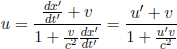
in the direction along the x-axis. The inverse transformations from frame S to S’ can easily be obtained by replacing v with –v.

Transverse Addition
In a new set-up, an observer in S’ now observes a particle to travel at  Keep in mind that S’ travels at v relative to S in the positive x-direction. We would again like to determine the particle’s velocity (ux, uy) in frame S.
Firstly, note that this motion in the y’-direction does not change the validity of the previous equation. The u and u′ just need to be substituted by their corresponding x and x’ components, ux and u′x which are the particle’s velocities in the x and x’-directions in frames S and S’ respectively. That is,

Moving on, we are concerned with finding uy. Using the Lorentz transformations once again, we obtain
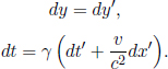

in the direction along the y-axis. Similarly, the inverse transformations from frame S to S’ are
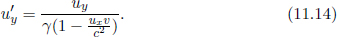
It is paramount to note that the transformation of the time elapsed between two events between frames S and S’ is independent of the relative y positions of the two events in the derivation above as the relativity of simultaneity only applies for events separated in the x- or x’-direction while the time dilation effect is only dependent on the relative velocity between frames.
Acceleration Transformations
It is also useful to determine how an acceleration a in inertial frame S will transform to the acceleration a′ in inertial frame S’. It is known from the velocity transformations that

Then, taking the derivative of u′x with respect to ux and using the quotient rule,
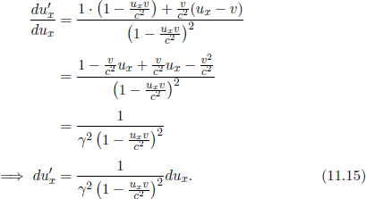
Furthermore, from the Lorentz transformations,
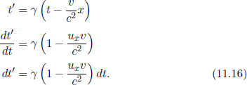
Dividing Eq. (11.15) by Eq. (11.16),
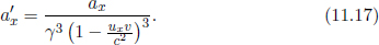
Similarly, from the transverse velocity addition,
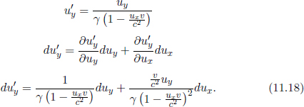
Dividing Eq. (11.18) by Eq. (11.16),

Therefore, we see that accelerations are no longer invariant when switching between inertial frames in special relativity — contrary to the situation in Galilean relativity.
Proper Acceleration
When objects are accelerating, there isn’t one inertial frame associated with them. However, a momentarily co-moving reference frame (MCRF) is useful in analyzing its motion. An MCRF is an inertial frame that travels at the same instantaneous velocity of the particle with respect to another inertial frame S (defined as the lab frame). Thus, the instantaneous velocity of a particle is zero in an MCRF defined at that instant. As an object accelerates, we have to switch from one MCRF to another new MCRF at every instant as the velocity of the object in frame S changes. With this definition, the proper acceleration of an object is the acceleration of that object observed in the MCRF defined at that instant. The transformation from the acceleration of an object in frame S to that in its MCRF can be obtained from Eqs. (11.17) and (11.19) via adroit substitutions. Firstly, we choose the coordinate systems of S and the MCRF such that the velocity of the particle is solely along the x-direction in frame S (though with this definition, the axes may have to be modified constantly in a manner analogous to how polar unit vectors change with the angular coordinate θ). Then, we can substitute uy = 0 and v = u into Eqs. (11.17) and (11.19) to obtain the relevant transformations. For the following section, we will use γu instead of γ where

to remind ourselves that v = u. Thus, substituting v = u and uy = 0 into Eqs. (11.17) and (11.19), the proper accelerations of a point particle in the x’ and y’-directions, αx and αy are


Problem: A particle is undergoing circular motion with a velocity u and a radius of orbit r in the lab frame. Find the magnitude of its proper acceleration.
The centripetal acceleration of the particle in the lab frame is

Since the instantaneous acceleration of the particle is constantly perpendicular to its instantaneous velocity, its proper acceleration is given by Eq. (11.21).

One-Dimensional Motion Under Constant Proper Acceleration
In this section, we consider the motion of a point particle, undergoing a constant proper acceleration, as observed in the lab frame S. It is assumed that the direction of the initial velocity of the particle is parallel to that of its acceleration in frame S. As such, we do not have to constantly modify the orientation of the axes of frame S and the MCRF to ensure that uy = 0 — reducing this to a one-dimensional problem in spatial terms (all quantities in this problem will be with respect to the x-direction that has been aligned with the direction of concern). From Eq. (11.20),

where α is the proper acceleration and a is the acceleration of the particle in frame S. The right-hand side can be written as  where t is the time in S, as seen from the fact that

Thus,

Before we integrate this expression, we claim that we can always define an origin in time such that u = 0 at t = 0. This can be subsequently justified (after finding u(t)) by showing that for any given value of velocity u0, there is a time t for which u(t) = u0. Integrating and applying the proposed initial conditions, we obtain

Substituting 

where the right-hand side is a monotonically increasing function in u. Thus, for a given value of u, we can always find a unique, corresponding value of t — implying that we can indeed set a temporal origin such that u = 0 at t = 0. Next, solving for u,
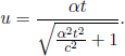
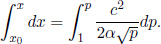
Integrating and letting x = x0 when t = 0,

Substituting the expression for p back into the equation above and rewriting,
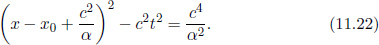
We can choose a spatial origin such that  Then,
Then,
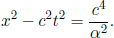
Note that we only need to consider the x > 0 region of this graph if α > 0, and the x < 0 region otherwise. It is always possible to choose the coordinate system of frame S such that the initial conditions above (u = 0 and  at t = 0) are satisfied. As we can see, the motion of the point particle is a hyperbola on the space-time diagram in frame S.
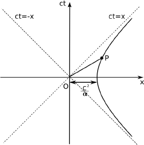
Figure 11.23:World line of particle undergoing constant proper acceleration in frame S
As t → ∞, x2 → c2t2 which implies that 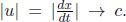 This is a limit that makes sense in the context of special relativity as the particle’s speed cannot surpass c. Now there are some interesting properties of this hyperbola. Consider a point P on the hyperbola shown in Fig. 11.23. The gradient of line OP can be calculated as follows. The x-coordinate of P in terms of t is
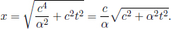
The gradient is then
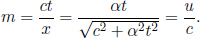
We see that the line OP is simply the superimposed instantaneous x’-axis of the MCRF (when the particle is at P) as it subtends an angle tan  with the positive x-axis! What this means is that a so-called pivot event, which is the origin O in this case, is always simultaneous with the instantaneous event of the particle in an MCRF. From Eq. (11.22), it can be seen that the pivot event is at
  in general for a point particle, undergoing constant proper acceleration α in the x-direction, that is located at x = x0 with zero speed at t = 0 in frame S. If we choose the pivot event to be the origin of the particle’s MCRFs too, the instantaneous event of the particle will also be at t′ = 0 in its MCRFs. The next useful property is even a stranger one. The distance between the pivot event in an MCRF, and the instantaneous event of the particle in the MCRF is given by length contraction to be

γu can be computed as
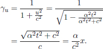
Thus,

which is a constant value. A quicker way of proving this is to consider the invariant interval. Since the particle’s event occurs at t′ = 0 in the MCRF, we immediately obtain from the equation of the hyperbola
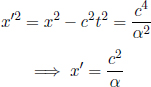
where we choose the positive value of x′ as it corresponds to the regime of interest. We see that not only is the pivot event always simultaneous with the instantaneous event of the particle in an MCRF, the distance between them is uniform across all MCRFs14! The weird part is that even though the point particle accelerates away from the pivot point in frame S, the distance between them never changes as measured in its own instantaneous inertial frame. This is because the increase in the length contraction factor perfectly cancels the increase in distance between the two events as observed in frame S.
The classical definition of a rigid object is one whose particles maintain a constant separation in space. This is in fact impractical even in classical mechanics. The interactions between particles of an object are electromagnetic in nature, thus the speed of an electromagnetic wave imposes a speed limit on force propagation speed through the object. In fact, the force propagation speed in matter is the speed of sound in that medium. Thus, if one end of the object experiences a sudden change, such as an abrupt stop, the other end of the object cannot instantaneously respond to it. In the case of a sudden stop, at the next instant, the ends of the object will be closer to each other, compressing the object and thus changing the relative positions of the particles on the object. This limitation also holds in the context of special relativity, as signals cannot travel faster at a speed greater than c which is, theoretically, the maximum possible speed.
The next flaw in the classical definition of rigid objects pertains to a relativistic effect. A moving object in a certain inertial frame is length-contracted. Thus, an object does not maintain a constant separation in space across different inertial frames. In this sense, the criteria of maintaining a constant separation in space is ambiguous as there is no explicit mention of the frame of reference. Therefore, the classical definition of a rigid object makes no sense in the relativistic case.
Failure to take into account the effects above may lead to fallacious reasoning and seemingly paradoxical situations.
Problem: Consider a variant of the classic pole-and-barn paradox. A pole and barn have proper lengths L. The pole travels towards the barn at a velocity v in the barn’s frame S. The end of the barn farther away from the rod, denoted as the rear end, is blocked by a massive and impenetrable door while its front end is initially open. In the barn’s frame, the pole is length-contracted and is able to fit into the barn. When the back of the pole enters the barn, the door closes in the barn’s frame and traps the pole. The pole then collides with the impermeable rear end of the barn and comes to a stop eventually.
In this frame, the back of the pole crosses the front of the barn. Thus, the front door of the barn can be closed. However, in the pole’s frame S’, the barn is length-contracted so the ladder is not able to fit inside the garage in the first place. How can the front door be closed then? In other words, does the back end of the pole really cross the front end of the barn?
The resolution to this apparent paradox is the fact that points on the pole are unable to stop instantaneously when the front end of the pole collides with the rear of the barn. Formally, we define the frame of the pole to be that of the particle at the rear tip of the pole as it is the last to stop. In frame S, the situation is depicted in Fig. 11.24.
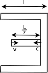
Figure 11.24:Frame S
The pole is length-contracted to a length  in frame S. Thus, the back end of the pole definitely crosses the front end of the barn in frame S. In fact, the eventual distance between the rear ends of the pole and barn must be smaller than Assume that a signal propagates at the speed of light c through the pole in frame S’. This is not really a physical situation but it can give us a rough notion of what happens in the boundary case by yielding an upper limit of the distance between the rear ends of the pole and barn. If the rear end of the pole crosses the front end of the barn under such an assumption, it will definitely do the same for an arbitrary signal speed which must be smaller than c. Next, it is assumed that when the signal passes by a certain part of the pole, that section immediately stops in the current frame.
Let the front end of the pole collide with the walls of the barn at t = 0 in frame S. The speed of the signal is still c in frame S as the speed of light is invariant across inertial frames. Then the time required for the signal to travel to the rear end of the pole in frame S is

as c + v is the relative velocity between the signal and the back end of the pole in frame S while is the Lorentz-contraeted length of the pole in frame S. An important point to note here is that the rear of the pole does not stop traveling until it receives the signal (i.e. the rear end continues to move for a while after the front end collides with the barn). Then, the eventual distance between the rear ends of the pole and barn is simply that traveled by the signal during the time t above.
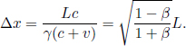
In frame S’, the situation is illustrated in Fig. 11.25.
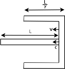
Figure 11.25:Frame S′
The length of the barn is contracted to while the length of the pole is its proper length L. The barn is now approaching the stationary pole. Similarly, we define the time of the collision between the front end of the pole and the rear of the barn to be t′ = 0 in frame S’. Then, the signal reaches the back end of the pole at

in frame S’. During this time, the impermeable rear wall would have traveled a certain distance while compressing the pole. We assume that the velocity of the wall does not change in this process. This could approximately be attained if the mass of the rear door is large. The distance traveled by the wall during this time interval is  Thus, the final distance between the rear ends of the barn and the pole is

in frame S’. This is smaller than the length of the barn in S’ as seen from the fact that
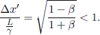
Thus, the back end of the pole crosses the front of the barn in both frames and the front door of the barn can be closed. Incidentally, there is also another interesting result which agrees with the principle of relativity: the ratios of the eventual distance between the rear ends of the pole and barn to the observed length of the barn are identical in both frames. This can be seen from the fact that
Born Rigidity
Considering the ineptness of the classical definition of a rigid object in the context of special relativity, novel concepts of a rigid object have to be developed. Max Born proposed that rigid objects in special relativity obey the following property: the distance between all points on a rigid object is locally constant in the MCRF of any point on the object. This definition rectifies the loophole in the classical definition due to length contraction. However, this definition of a rigid object is still physically impossible as it does not circumvent the limitation of the speed of sound in a body which is the first flaw highlighted in the section above. Despite this, it is still a viable analog of the classical definition since the classical definition also idealized the propagation of “signals” within a body.
To fulfil the Born criterion, the proper accelerations of the points of the body must satisfy a certain relationship. In that sense, in order to achieve Born rigidity, the motion of an object has to be planned carefully beforehand. It is an extremely restrictive class of motions.
We shall consider the case where all points on the Born rigid body undergo a one-dimensional motion due to a constant proper acceleration in the x’-direction (where the primed frame is its MCRF). Recall that a point particle that is initially stationary at x = x0 when t = 0 in the lab frame S and undergoing a constant proper acceleration α will follow a hyperbolic path with the pivot event at coordinate x = x0 –  Furthermore, in any MCRF of the particle at an arbitrary time t in frame S, the difference in the x’-coordinates of the particle and the pivot event, measured simultaneously, is
Therefore, if the pivot events of all points on an object coincide, the Born rigid condition will be satisfied! Consider two points on the object at coordinates x1 and x2, when t = 0 in frame S, undergoing proper accelerations α1 and α2 respectively. If their pivot events are concurrent and if we consider the MCRF of any of the two particles at any instant in time, the two particles have a difference in x’-coordinates of  with the pivot event, as measured simultaneously. The pivot events of the two particles are shown to be concurrent at the origin O in Fig. 11.26. The diagonal line represents a possible line of simultaneity if we were to consider the MCRF of either of the particles, defined at the corresponding point of intersection of the line with its hyperbolic path (actually, the two MCRFs are identical as the particles possess the same velocity at the points of intersection). The bold segment indirectly15 reflects the difference in x’-coordinates between the two particles, measured simultaneously in their MCRF, as superimposed on the space-time diagram of frame S. The “proper length” between them is maintained at
  in the MCRF (Fig. 11.27) as the distance between each individual particle and the pivot event is constant. Furthermore, in order for
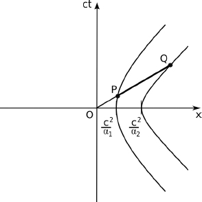
Figure 11.26:World lines of two points on a Born rigid object in frame S
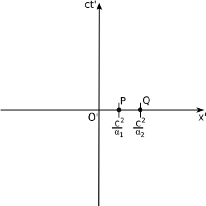
Figure 11.27:Points P and Q in one MCRF
the pivot events to coincide in the first place,
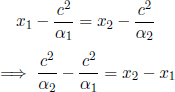
which shows that the distance x2 – x1, which is also the initial distance at t = 0 in frame S, is maintained throughout the motion in any MCRF of either of the particles. Thus, if an object spans the entire region between coordinates x = x1 and x = x2 and the proper acceleration is α0 at some x0 (x1 ≤ x0 ≤ x2), the proper acceleration, α, of a point at an arbitrary x-coordinate x (x1 ≤ x ≤ x2) must satisfy
in order for the object to be Born rigid. With this, the length of the rod in any MCRF is also maintained at x2 – x1. We see that this definition of a rigid body is extremely restrictive, as the motion of one point on the object constrains the motion of all other points if all points were to undergo constant proper accelerations. However, note that Born rigidity is merely one of the many proposed definitions of a relativistic rigid object — other less restrictive definitions have also been suggested.
Consider a source, that emits waves (not necessarily electromagnetic), approaching a stationary observer at a speed v in frame S in Fig. 11.28.

Figure 11.28:Source approaching an observer
We would like to determine the frequency of the waves received by the observer in frame S if the waves travel along the line joining the source and the observer. The frequency and the speed of the waves emitted in the frame of the source S’ are f′ and u′ respectively.
There are two main effects which lead to a shift in the observed frequency here. The first is time dilation which causes the observed frequency of emission in the frame of the observer to differ as the source is moving. The second factor is the relative motion between the source and the observer during the time interval between consecutive emissions of wavefronts — the essence of the classical Doppler effect.
Let T and T′ be the observed period of emission of the source in frames S and S’ respectively. Then by time dilation, T = γT′ as the observer sees the clock on the source running slow. In frame S, imagine a wavefront emitted at a certain instant. During the time interval between this instant and the release of the next wavefront, the source would have traveled a distance vT = vγT′. The emitted wavefront would have traveled a displacement uT where u is the velocity of a wavefront in frame S. It can be computed via the velocity-addition formula.

Thus, if we define λ and λ′ to be the observed wavelengths of the waves in frames S and S’ respectively, λ can be calculated as
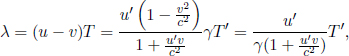
which corresponds to the distance between consecutive wavefronts in frame S. Thus, the observed frequency of waves received by the observer is

In the case of light, u′ = c and we obtain

Remember that v is defined to be positive if the source and observer are approaching each other and negative if they are retracting away from each other. When v > 0, the frequency of the received waves is larger in frame S than S’ and the waves are said to be blue-shifted (higher frequency and thus shorter wavelength). When v < 0, the converse occurs and the waves are said to be red-shifted (lower frequency and thus longer wavelength). This result is truly relativistic as it only depends on the relative velocity between the source and observer as observed in the frame of one — as opposed to the non-relativistic Doppler effect which has different dependencies on the velocities of the observer and source in the lab frame.
Lastly, there is generally a distinction between an observer observing and seeing something. In the context of waves, when we refer to the frequency of the emitted waves as observed by an observer, we usually mean the frequency of the waves that are emitted at the source in the frame of the observer (i.e. the emission event is of concern). On the other hand, the frequency of waves as seen by an observer explicitly refers to the frequency of the waves that reaches him as observed in his frame (i.e. the receiving event is of concern). In the case of the longitudinal Doppler effect, the frequency of emission observed by the observer is  (due to time dilation solely) while the frequency of waves seen by the observer is
  (both mentioned effects have to be accounted for).
Problems
As a word of advice, it is often easier to express everything in units of c, the speed of light in a vacuum, to preclude c’s from floating around everywhere. For example, instead of v = 0.9c, one can rewrite it as v = 0.9. γ then becomes  Afterwards, one can add back the c’s at the appropriate positions by dimensional analysis. For instance,
  in units of c becomes
  by observing that there is an addition between uv, which has units in m2s′2, and a constant 1, which is dimensionless.
Fundamental Consequences
1.Superluminal Travel*
Adrian shines a laser towards the Moon and forms a red spot on a crater. He claims that if he twists his wrist, the spot on the Moon will travel a great distance in a very short amount of time and thus achieve a superluminal speed — thus violating special relativity. What is wrong with his reasoning?
Now, Betty invents the following thought experiment. Suppose that you build a pair of scissors with very long blades. If you decrease the angle between the handles of the scissors during a certain time interval, the angle between the blades should also decrease by the same amount in the same time interval. Then, points arbitrarily far away from the joint should travel at superluminal speeds as the angular distance covered is fixed! Where does Betty’s idea fail?
2.Muon Decay*
Muons have a half-life of proper time th. They are released at a distance L above the surface of the Earth and travel at a constant velocity v towards the Earth. What is the proportion of muons that reach the surface of the Earth? Solve this problem from both the muons’ frame and the Earth’s frame.
3.Rod*
Consider two frames S and S’; S’ is traveling at a velocity v along the positive x-axis of frame S. A rod, of length L as measured in its rest frame S, subtends an angle θ1 with the x-axis in frame S. Find the angle subtended by the rod and the x’-axis, θ2, in frame S’.
4.Ladder-and-Barn Paradox*
A ladder of proper length, L, travels at a relative velocity v towards a barn with proper length L. The barn has two doors at its ends that are initially open. From the frame of the barn, frame S, the ladder is length-contracted and thus fits into the barn. However, from the frame of the ladder, S’, the barn is length-contracted and thus the ladder does not fit. Resolve this apparent paradox. Consider the following: one can show that the ladder fits in the garage by closing the two doors of the barn simultaneously in the current reference frame during the brief period of time that the ladder is completely inside the barn. The doors are then opened to release the ladder when it is about to collide with the doors (so that the doors do not affect the ladder’s motion).
5.Spaceships*
Consider a spaceship A of proper length L traveling towards an identical spaceship B at a relative velocity v. When the right of A reaches the right of B, a cannon is simultaneously fired from the left end of A in S’, the frame of spaceship A. In frame S’, spaceship B is length-contracted which causes the cannon to miss. However in ship B’s frame S, spaceship A is length-contracted and the cannonball seemingly hits. Resolve this apparent paradox. Warning: misleading figure.
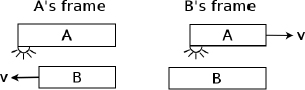
Velocity Addition and Doppler Effect
6.Stellar Aberration*
A stationary light source is situated at the origin of frame S. It emits a flash that is received by a receding observer traveling at a velocity v in the positive x-direction. Let the observer’s frame be S’. If θ and θ′ are the angles subtended by the path of the light and the positive x-axis in frame S and the positive x’-axis in frame S’ respectively, show that
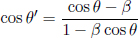
where  is defined to be positive in the positive x or x′-direction.
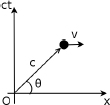
7.Relative Speed*
Consider two particles traveling at constant velocities v and u in the lab frame. The angle subtended by their velocities is θ. Find the speed of one particle in the frame of the other.
8.Another Velocity Addition Derivation*
A train of proper length L is moving longitudinally with velocity v relative to a stationary observer on the ground. A person inside the train, standing at the tail end of the train, throws a ball horizontally with constant velocity u towards the front (assume that there is no gravity) as observed in his own frame, and simultaneously sends a light signal in the same direction. The light hits the front end of the train and is reflected back, meeting the ball at some point. This meeting point of interest is a certain distance from the tail end of the train (as observed in the ground or train’s frame).
(a)Find the ratio R of this distance to the proper length of the train L in the train’s frame.
(b)In the ground frame, find the ratio R′ of this distance to the observed length of the train. In your answer, let the length of the train and the velocity of the ball be L′ and u′, respectively in the ground frame.
(c)What can you say about your answers in a) and b)? Explain. Hence, derive u′ in terms of u and v.
9.Two Trains**
Two identical trains are traveling at speeds  towards the right in frame S. The faster train is initially behind the slower train. Define events P and Q to be the front of the faster train crossing the back of the slower train and the back of the faster train crossing the front of the slower train respectively. When event P occurs in frame S, an observer R begins walking from the back of the slower train to the front of the slower train. Coincidentally, the time during which he reaches the front of the slower train coincides with event Q. Find the velocity of the faster train in the frame of the slower train. Thus, find the speed of observer R in the frame S. (“An Introduction to Mechanics”)
10.Velocity Additions via Rapidity**
All velocities in this problem are assumed to be aligned in the x-direction. The rapidity ϕ of a particle or frame with respect to a frame S is defined as

where v is the velocity of the particle or frame with respect to S. tanh ϕ =  is the hyperbolic tangent function. Show that if a particle has rapidity ϕ1 with respect to frame 1 and frame 1 has rapidity ϕ2 with respect to frame 2, the particle has rapidity ϕ1 + ϕ2 with respect to frame 2. It may be useful to know that
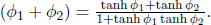
Now, consider a particle which travels at a velocity v1 with respect to frame S1, which travels at velocity v2 with respect to frame S2, which travels at velocity v3 with respect to frame S3, and so on until frame Sn–1 which travels at velocity vn with respect to frame Sn. All of these velocities are aligned. Show that the velocity of the particle in frame Sn is
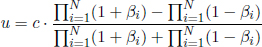
where 
11.Collision**
In the lab frame S, a particle is traveling at a velocity v towards an identical, stationary particle. From classical mechanics, we know the resultant velocities of the two particles must be perpendicular after the imminent collision as they have equal masses. Show that it is impossible for the two particles to have non-zero velocities that are perpendicular in special relativity by considering another inertial frame where the situation is symmetric, and assuming that the dynamical laws are reversible. We do not know anything else about the dynamical laws in special relativity now. In fact, you can show that the angle of separation must be smaller than 90°. Finally, prove the classical result, that a head-on collision causes the particles to exchange velocities in frame S, holds in the context of special relativity.
12.General Doppler Effect**
A source that emits photons at frequency f′ in its own frame, S’, is moving across the field of vision of a stationary observer at the origin in the frame of the observer, S. What is the observed frequency of emissions by the source in frame S? Now, what is the frequency of the photons emitted at angle θ in the left diagram below, as seen by the observer when the photons eventually reach his eyes? At the instant where the source is at the closest distance of approach to the observer, what is the frequency of the photons that enter the eyes of the observer? When the observer sees the source at the closest distance of approach, what is the frequency of the photons that enter the observer’s eyes? You may find the pictures below to be useful.
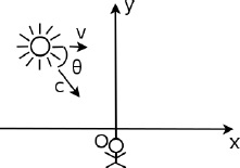
Figure 11.29:General situation

Figure 11.30:Last situation
13.The Twins’ Paradox Revisited**
Consider the twins’ paradox set-up again. Now the two twins send out a radio pulse once per second in their own frames. As before, twin A travels to the distant star, that is a distance L from the Earth in twin B’s frame, and back at speed v while twin B remains on the Earth. During the entire process,
(a)How many pulses did twin A broadcast in total?
(b)How many pulses from B did A receive in total? Hence, who does twin A conclude to be younger?
(c)How many pulses did twin B broadcast in total?
(d)How many pulses from A did B receive in total? Hence, who does twin B conclude to be younger?
14.Moving Glass**
In lab frame S, a stationary source emits light of frequency f in vacuum, in the positive x-direction. The photons then pass through a glass block of refractive index n and proper length l that is traveling at a velocity v in the positive x-direction. Determine the time taken by the light to cross the block, the frequency and wavelength of light inside the block in the frame of the block, S′. Ditto for the lab frame.
Minkowski Diagrams
15.Simultaneous Lamps*
In the lab frame S, three lamps at coordinates x1, x2 and x3 are observed to be illuminated at times t1, t2 and t3. At t = 0 in S, a car is observed to travel from the origin at a constant velocity v > in the positive x-direction. Under what conditions will the person P in the car observe all three lamps to be lit up simultaneously? Next, assume that P observes the events to occur at t′ = 0 in his own frame S′. Let the time intervals between the illumination of the lamps and the receipt of the corresponding photons be Δt1, Δt2 and Δt3 in frame S′. If person P observes the ratio of these intervals to be Δt1 : Δt2 : Δt3 = 1:2:3, and given x1, determine the x-coordinates of the other lamps in frame S and the times at which the lights were lit up in frame S. Solve this problem via a Minkowski diagram.
16.Diverging Cars**
In the lab frame, car 1 travels at speed v1 = tan15°c in the negative x-direction while car 2 travels at speed  in the positive x-direction. The cars start from the origin O at time t = 0. At a certain later time, car 1 emits a light signal in the positive x-direction. If an observer in car measures the time interval between the emission event and the receiving event by car 2 to be t′, determine the distance that car 2 has traveled from its initial position in the lab frame when it receives the light signal with the aid of a Minkowski diagram.
Proper Time
17.Particle’s Motion*
The velocity of a particle as a function of time t in the lab frame is given by
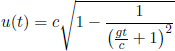
and is oriented along the positive x-axis.
(a)Show that the proper time elapsed in the particle’s frame is 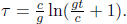
(b)Let x denote the instantaneous x-coordinate of the particle in the lab frame. If the particle starts at the origin in the lab frame originally, show that 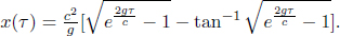
18.World-Line*
In the standard configuration, a particle moves in the x-direction. In the lab frame, its x-coordinate is described by
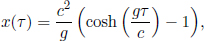
where g is a constant with units of acceleration and τ is the proper time of the object. Define γu as the gamma factor ascribed to the speed of the object u in the lab frame.
(a)Express u in terms of γu, g, c and τ.
(b)Hence, express γu in terms of g, c and τ.
(c)Using the result of (b), re-express u solely in terms of g, c and τ .
(d)Express t as a function of τ and hence, u(t) and a(t). Show that u(t) and a(t) make sense for t → ∞.
Solutions
1.Superluminal Travel*
Let the distance between Adrian and the Moon be L. After Adrian has shifted the direction of the laser, it takes time, on the order of  for photons emitted in this new direction to form a spot on the Moon. Suppose that the direction of the laser changes by a small angle θ in time Δt. The distance that the spot moves is on the order of Lθ. Therefore, the “average velocity” of the spot is on the order of
  in the time interval Δt, especially if θ is small. The spot on the Moon seemingly achieves superluminal travel! Well, the resolution to this paradox is that the spot is not a physical entity and is unable to carry information. The spot simply marks the location at which incident photons impinge on — its movement is no different from a fickle cartographer suddenly placing a dot on his map to define a new origin (and this requires no time). Therefore, the spot does not need to comply to physical laws such as special relativity and its speed can seemingly exceed the speed of light (but it makes no sense to define a speed for such an intangible construct anyway). However, the mediating particles, which are photons in this case, must still be unable to achieve superluminal speeds.
Betty’s argument breaks down when she claims that the angle between the blades should also decrease by the same amount in the same time interval as the rigid body assumption is inherently flawed. The scissors cannot remain rigid and points on the blade do not cover the same angular distance in the same time interval (even if they rotate by the same angle so eventually). Firstly, it takes time for signals to travel from the handles to points on the blade to inform them that they should move. Therefore, points far away will begin moving at a later time and the rigid body assumption fails. Afterwards, when different points on the blade start to move, they still cannot move at a speed faster than the speed of light. Hence, they cannot “teleport” to the correct positions to maintain the rigid body property. The points on the blade do not and need not cover the same angular distance in the same time interval and hence Betty’s idea fails.
2.Muon Decay*
From the frame of the muons, the distance between its initial position and the Earth is length-contracted. Thus, the total time taken for the journey in the muons’ frame is

In the frame of the Earth, the muons require a time interval of

to reach the Earth. However, an observer on the Earth will observe that the clocks on the muons tick slower due to time dilation. Thus, the time elapsed on the clocks of the muons during this process is

which is consistent with the result above. The proportion of the muons that reach the Earth is then

as the proportion left after n half lives is 2–n.
3.Rod*
The difference between the x and y-coordinates of the two ends of the rod in frame S at simultaneous times are
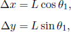
where L is the length of the rod in frame S. The difference between the x’- and y’-coordinates of the two ends of the rod in frame S’ at simultaneous times are
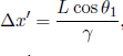

due to length contraction. Remember that length contraction does not occur in the transverse direction. Then, the new angle subtended by the rod and the x’-axis is

4.Ladder-and-Barn Paradox*
The resolution is that it is perfectly fine for observers in the different frames to reach different conclusions as to whether the ladder will fit into the barn. In this problem, we define the fronts and backs of the ladder and barn to be the sides that are the closest to and furthest away from each other. Even though the front and back doors of the barn may trap the ladder for a period of time in frame S, they fail to do so in frame S’ due to the relativity of simultaneity. Concretely, let the origins of the two frames, O and O’, coincide at t = t′ = 0. At t = 0, the rear end of the ladder crosses the front of the barn in frame S. Thus at this instant, both front and rear doors close simultaneously in frame S. Let events 1 to 4 be defined as that of the front door closing, rear door closing, front door opening and rear door opening respectively. The (x, ct) coordinates of these events in frame S are
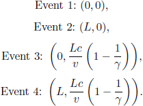
The ct-coordinates of events 3 and 4 are obtained by utilizing the fact that the gap between the front end of the ladder and the rear of the barn is  at time t = 0 as the ladder is length-contracted in frame S. Evidently, the ladder is completely inside the barn during the time interval between t = 0 and
  in frame S. Applying the Lorentz transformations to these events, the corresponding coordinates in frame S’ can be obtained.
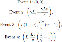
Note that the back of the rod still reaches the front of the barn at event 1 and that the front of the rod still reaches the back of the barn at event 3. This is because, they are technically the same events as they occur at the same x-coordinate and time in frame S. Rearranging these events in chronological order in S’,
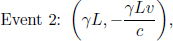
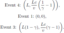
This means that the rear door of the barn first closes before the front of the ladder reaches the back of the barn and then opens when the front end of the ladder reaches the rear of the barn such that the ladder is released. Afterwards, the front door of the barn closes as the rear of the ladder passes by it. Lastly, the front door opens. It can be seen that there is no moment at which the ladder is completely trapped within the closed doors in frame S’ due to the relativity of simultaneity. It is perfectly fine for observers in the two frames to reach different conclusions in this set-up, as whether the ladder fits into the barn is merely a human construct and not a physical event. A brief outline of the entire process in the two frames is depicted in Figs. 11.31 and 11.32.
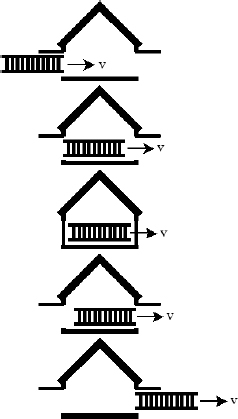
Figure 11.31:Situation in frame S
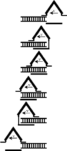
Figure 11.32:Situation in frame S’
5.Spaceships*
The second reasoning is flawed as the event of the right of A reaching the right of B and the firing of the cannon are no longer simultaneous in frame S (the diagram is misleading). Let the origin of the two frames, O and O’, coincide at time t = t′ = 0. Let the (x′, ct′) coordinates of the firing event in frame S’ be
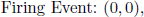
and that of the right of A reaching the right of B in S’ be

The cannon obviously misses as the left and right ends of spaceship B are at x-coordinates  and L at t′ = 0 respectively. Then, the (x, ct) coordinates of these two events in frame S can be obtained via the Lorentz transformations.
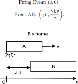
Figure 11.33:Corrected diagram of the situation in B’s frame, S
Referring to Fig. 11.33, it can be seen that the firing event occurs before the right of A reaches the right of B! This can also be concluded from the fact that the firing event is the rear clock as observed in frame S, which leads the front clock (event AB) by  Next, from the coordinates of event AB, we can conclude that the rear end of the stationary spaceship B is at x-coordinate
at all times t in S, where 0 is the x-coordinate of the firing event. Hence, the cannon still misses in S.
6.Stellar Aberration*
Since the speed of light is c in both S and S’, the x and x’-components of the photon’s velocities in S and S’ are ccos θ and c cos θ, respectively. By the longitudinal velocity addition formula,
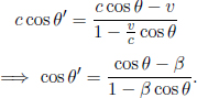
7.Relative Speed*
Let u|| and  be the components of u parallel and perpendicular to v respectively. Then,

Thus, in the frame of the particle traveling at velocity v, these two components obey the following velocity transformation rules:
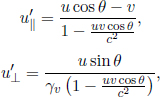
where  Thus, the speed of the other particle in this frame is
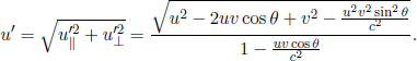
8.Another Velocity Addition Derivation*
(a) In the train’s frame, the total distance traversed by the ball and the photon until their collision is 2L. Therefore, the time of collision is  and the distance between the ball and the back end of the train at this juncture is

(b) Since the distance between the front end of the train and the photon narrows at a rate c – v in the ground frame, the distance traversed by the photon until it impinges the front end of the train is  The total distance covered by the ball and the photon until their collision is then
  such that the time of collision is
  The distance between the ball and the back end of the train at this juncture is
  increases at a rate of u′ – V.

(c) The two ratios must be equal, else this experiment can be used to distinguish between the two inertial frames — violating the principle of relativity.

9.Two Trains**
Let us define the faster and slower trains to be A and B respectively. By the relativistic longitudinal velocity addition formula, the velocity of train A in the frame of B is
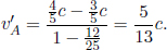
Let us now consider the frame of the observer. In the frame of the observer, only the two trains are moving and he or she is stationary. The two trains must travel at velocities of equal magnitudes and opposite directions in order for events P and Q to occur at the location of the observer. In search of a contradiction, suppose that the trains traveled at different speeds — the faster train would be length-contracted to a greater extent while traveling at a greater speed, causing its end to reach the observer in a shorter time. Let the magnitude of these velocities be v. Thus, train A travels at speed v towards the right while B travels at speed v towards the left. The velocity of train A in the frame of train B obtained by applying the velocity addition formula should be the same as that derived earlier. Thus,
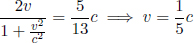
where we have rejected the impractical solution v = 5c. Next, let the velocity of the observer be u in frame S. Then again, the relativistic addition of  to u should give
  which corresponds to the velocity of train A in frame S. Thus,

Solving,

10.Velocity Additions via Rapidity
Let β1 = tanh ϕ1, ϕ2 = tanh ϕ2 and β′ be the β factor of the particle in frame 2. By the relativistic velocity addition formula,

Therefore, the rapidity is additive across frames. In the second part of the question, the rapidity of the particle with respect to frame SN is

Then

Now, simple manipulations of tanh  yield
yield
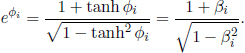
Thus,
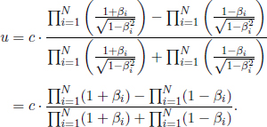
11.Collision**
In the lab frame S, define our coordinate system such that v is in the positive x-direction. Number the moving particle 1 and the other particle 2. Now, consider the inertial frame S’ where particle 1 travels at velocity u while particle 2 travels at velocity –u in the x’-direction. Since particle 2 was stationary in S, S’ must travel at velocity u relative to S. Thus, u can be determined by applying the velocity addition formula to v.

The actual value of u can be solved from the quadratic equation above but it is not particularly important here. The pivotal point is that it exists for some value smaller than c. Now in this frame, the situation exhibits mirror symmetry. Therefore, if the final velocity of particle 2 in S’ makes an angle θ anti-clockwise with the positive x’-axis, the final velocity of particle 1 in S’ must subtend an angle θ anti-clockwise with the negative x’-axis. Furthermore, the magnitude of their final velocities must still be u as the set-up must be reversible. Then, the final velocities of particles 1 and 2 are (–u cos θ, –u sin θ) and (u cos θ, u sin θ) in frame S’. The y-direction is chosen such that the velocities lie in the xy-plane. The final velocities of the two particles in frame S can then be obtained from the velocity addition formula, as S’ travels at velocity u relative to S.
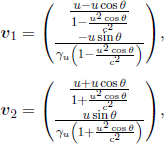
where  The dot product of the two velocities is
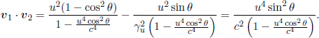
This expression can only be zero when θ = 0 or θ = π. However, in both cases, the dot product is zero, not because the velocities are perpendicular but because one of the velocities is zero. Therefore, it is impossible for the particles to leave with perpendicular non-zero velocities in frame S. In fact, if we let ϕ denote the angle of separation between v1 and v2,
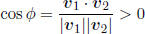
which implies that  Next, when the particles undergo a head-on collision, θ = 0 which yields

We do not need to take an intermediate step in explicitly evaluating u to determine  in the x-component of v2, as it is simply the inverse transformation, from S’ to S, of the transformation from v in S to u in S’.
12.General Doppler Effect**
In all scenarios, the observer observes the source to emit a wavefront every T = γT′ seconds. Thus, the observer observes the source to emit at a lower frequency  Moving onto the general problem, consider Fig. 11.34.
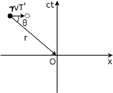
Figure 11.34:Transverse Doppler effect at an arbitrary angle in frame S
Consider two beams emitted by the moving light source in frame S. The time interval between these two beams is T = γT′ in S. In this time interval, the source travels v cos θT = γvT′ cos θ along the first beam — thus narrowing the wavelength. The perceived wavelength of these light waves is then

Thus, the perceived frequency of these wavefronts by the observer is
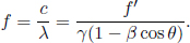
Now, we shall analyze how to substitute θ for the last two situations in the problem. In the first scenario, the light that reaches the eyes of the observer must have been emitted before the source reaches the point of closest approach in frame S. In the second situation, the wavefront of concern is emitted when the light source reaches the closest point of approach in frame S. Thus, the wavefront is emitted vertically downwards in frame S. Evidently,  radians in the second case — leading to a perceived frequency of

Now, in the first situation,  as the ratio between the distance traveled by the beam (emitted before crossing the y-axis) and the distance traveled by the source must be c : v. Substituting this expression into the formula for f,

13.The Twins’ Paradox Revisited**
(a) Again, there are two different inertial frames associated with twin A during his outbound and inbound journeys. In both of twin A’s frames, the distance between the Earth and the star is length-contracted. Thus, the whole process takes

and he releases

pulses.
(b) During the first half of the journey, twin A receives pulses from B at a frequency of  due to the relativistic Doppler effect as the Earth travels away from twin A in A’s frame. During the second half of the journey, the frequency of the pulses instantaneously becomes
  when twin A switches frames. Therefore, the total number of pulses from B received by A is

Hence, twin A concludes that he is younger than twin B by a factor of 
(c) The total time of the journey in B’s frame is simply

Thus, he emits

pulses.
(d) The important point to take note of is that twin B does not immediately receive pulses of a higher frequency when twin A turns around as there are already pulses that are en route to twin B. The total time during which B receives low-frequency pulses from twin A is  where the first term arises during the first half of the journey of twin A and the second term corresponds to the subsequent time taken for the last low-frequency pulse to reach B. For the rest of the
  time, B receives high-frequency pulses. Therefore, the total number of pulses emitted by A that is received by B during the entire process is

Therefore, twin B similarly concludes that twin A is younger than him by a factor of
14.Moving Glass**
In the frame of the block, S′, the length of the block is just its proper length l and the velocity of light with respect to the block is just  but the light is Doppler-shifted. The time taken for the light ray to exit the block in S′ is just
  The frequency of light in the block fS′ is related to the frequency in vacuum f by
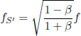
where  this is the longitudinal relativistic Doppler formula as the source now moves in the frame of the block. Note that the frequencies of light in vacuum and in the block must match as the block is stationary. The wavelength inside the block in frame S’ is then

Now, consider things in the lab frame — the situation is much trickier. We know that light travels at speed  with respect to the glass block. Therefore, the velocity of light within the block in the lab frame is given by the velocity addition formula as

Next, the length of the glass block in the lab frame is  where
where  as it is Lorentz-contracted. Now, notice that the block also travels at v, in an attempt to chase after the light. Therefore, the relative velocity between the light and the glass block in the lab frame is c′ – v. The total time taken for the light to escape the glass block is
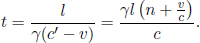
To determine the frequency of light inside the block, first observe that light from the source impinges on the closer end of the block at a frequency  as the block retracts at a velocity v (this is just the classical Doppler effect as there is no time dilation). However, note that this is not the frequency of light inside the block. When the edge of the block receives light, its atoms re-emit light into the block — that is, the end of the block now acts a source. Observe that the end of the block is moving at speed v. The light inside the block is then Doppler-shifted again as the “source” (the edge of the block) is now moving in the direction of the waves it emits. Thus, we need to multiply
  by a correction factor of
  as the wavelength inside the block decreases by a factor of
  in the lab frame. The frequency in the block in the lab frame is thus

The wavelength of light inside the block in the lab frame is
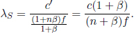
15.Simultaneous Lamps*
Consider a Minkowski diagram in the lab frame S (depicted in Fig. 11.35) and plot the illumination events of the lamps as points A1, A2 and A3.
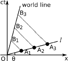
Figure 11.35:Minkowski diagram in frame S
A line of simultaneity of the car, when superimposed on the current diagram, is inclined at an angle θ = tan–1 β anti-clockwise from the positive x-axis. Therefore, the events must be collinear through a line l that subtends an angle θ with respect to the horizontal. This requires
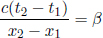
and
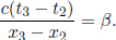
Since we know that a line  represents the world line of the car and the ct’-axis when superimposed on the current Minkowski diagram, line l must cross the origin of frame S, as shown in the figure above (in order for the lights to be observed at t′ = 0 by person P). Now draw three 45° lines, which represent the path of photons, from the corresponding illumination events and label their intersections with the world line of the car as B1, B2 and B3 respectively. These events denote person P receiving the photons. Since
 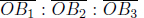 = 1:2:3 and
 = 1 : 2 : 3 by similar triangles. Since
  x1 : x2 : x3 = 1:2:3. Thus,

Finally, the respective times of the illumination events can be calculated via cti = tan θxi = θxi.
16.Diverging Cars**
Figure 11.36 is a Minkowski diagram in the lab frame S. We first draw the world lines of cars 1 and 2, which are straight lines that subtend 15° and 30° with the ct-axis, respectively.

Figure 11.36:Minkowski diagram in frame S
Let event A be the emission of the light signal from car 1 and event B be the receiving event by car 2. Then, the photons take the path AB on the Minkowski diagram, which makes a 45° angle with the vertical. Now, we superimpose the x’ and ct’-axes of car 1 onto the current diagram. Draw a line that subtends 15° with the x-axis that crosses through B — this is a line of simultaneity with respect to car 1. Define the intersection of this line and the ct’-axis (which is just the world line of car 1) as C. Since the time between the emission event and the receiving event in frame S’ is t1 and since a time ct′ in frame S′ corresponds to a “length” of 
 on the superimposed ct′-axis in the Minkowski diagram of frame S,

Now, let us consider a few angles. Firstly, ∠O′BO = 60◦. Since ∠O′BC = 15° (recall that line BC is a line of simultaneity with respect to car 1), ∠CBO = 75°. Next, since lines AC and AB subtend 15° and 45° with respect to the vertical respectively, ∠CAB = 60 ° and ∠OAB = 120°. Then, ∠ABO = 180° – 45° – 120° = 15°. This implies that ∠CBA = ∠CBO – ∠ABO = 60°. Since ∠CAB = ∠ABC = 60°, ∠ABC is equilateral. Therefore,
Then,  is given by the sine rule.
The x-coordinate of event B is

17.Particle’s Motion*
(a) The infinitesimal proper time interval is

with


(b) Adopt the substitutions secy  and tan y secy dy
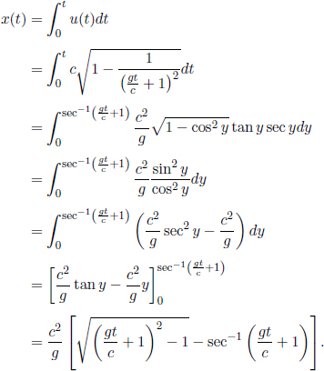
Observe that  Furthermore, from the result of a), we can write
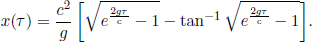
18.World Line*
(a) Since dt = γudr,
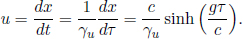
(b)

where we have chosen the positive root since γu ≥ 1.
(c)
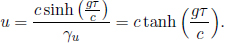
(d)
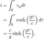
From the above,
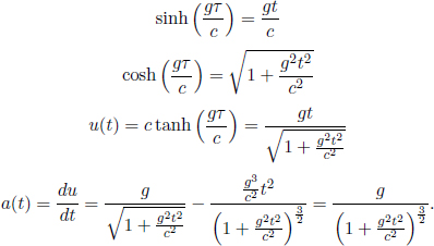
As 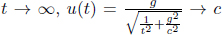 while a(t) → 0. This limit makes sense as the particle’s speed in the lab frame cannot exceed c.
1Note that there is a distinction here between the laws of motion (Newton’s laws) and all laws of physics. Galilean relativity was proposed to only apply for mechanical laws.
2See Appendix A.
3Clocks of different frames can be observed to possess different readings for the same event as they are different clocks.
4We can stop the clock once it is struck by lightning.
5Actually, we can deduce that  as x1 is akin to the length of a train in its rest frame (L′) while
  is the observed length of the moving train (L). Since we have used the result
 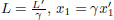 correspondingly.
6One way to see this is that if the ratio of two relatively stationary objects is different across inertial frames, we would be able to tell if we switched between inertial frames – violating the principle of relativity.
7Leading and trailing with respect to the direction of v (the velocity of frame S’ with respect to frame S).
8Observe that the first situation becomes the second if we swap S and S’ (technically, we need to reverse the direction of the velocity v but that only changes the direction of the “gradient” and not the magnitude). Therefore, if we switch the primed quantities in the first result  into the unprimed quantities, we obtain
  which is the second result (we have used
9We have used h, which is the height of the train in A’s frame, as the height of the train in B’s frame without any justification here. This is because length contraction does not occur in the transverse direction. Refer to the section on length contraction for further elaboration.
10The clocks still remain at the same x’-coordinates in S’ as they are stationary in S’
11Recall that our coordinate system consists of meter sticks!
12In this paragraph, we have assumed that the length scales along the ct and x-axes are the same (i.e. measure x in units of light distances such as light seconds). This is definitely not true in general, but it is indeed a convention in drawing Minkowski diagrams.
13Note that there may not be a single inertial frame associated with observer O as he might be accelerating.
14Actually, the invariant interval trivially and necessarily implies this.
15Indirectly, in the sense that the magnitude of the difference in x’-coordinates is different from the length of the bold line in frame S (concretely, we must divide this length by the scaling factor  where β is the tangent of the angle of inclination of the line).
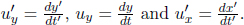 Thus,
Thus, and expressing