

Public spaces, such as corridors, lobbies, and concourses, are subject to a tremendous intensity of usage involving fluctuating peaks of activity and human occupancy loads. In office buildings, peaks relate to working hours. In transportation facilities patterns of usage are dictated by arrival and departure activities. In theater, convention centers, or sports centers, scheduling of events determines the periods of occupancy. Adequate provisions for human locomotion through these public spaces, as well as provisions for related convenience facilities are important design considerations.
The quality of the interface between the human body and the interior space impacts not only on the level of user comfort involved, but on the public safety. To determine door widths, corridor widths, and stair dimensions, body size must be the ultimate yardstick. Caution should be exercised in accepting prevailing standards or rules of thumb to establish critical clearances without questioning their anthropometric validity, even though these standards may be incorporated into existing codes or ordinances. It serves no purpose to conform to the language and not the intent of these codes, which is to ensure the public safety. The unit or increment of measurement that must be applied to establish proper width clearances must reflect current published maximum body breadth dimensions. The data selected must accommodate the majority of users. This is too critical a factor to be based on antiquated rules of thumb. The design of public rest rooms must also reflect this unit of measurement if they are to function properly. It is absurd, for example, to provide the number of fixtures that may be required by codes if the spacing selected will only allow half of them to be used simultaneously. In addition, public spaces should be responsive to the needs of the disabled user. Controls should be within reach of chair-bound people, stair design should accommodate elderly people, and human locomotion for ambulant disabled people should be barrier free. The drawings on the following pages are intended to call attention to some of the anthropometric factors to be considered in the design of public spaces. The first of these drawings deals with the basic unit of measurement: the maximum body breadth and depth of the human body.
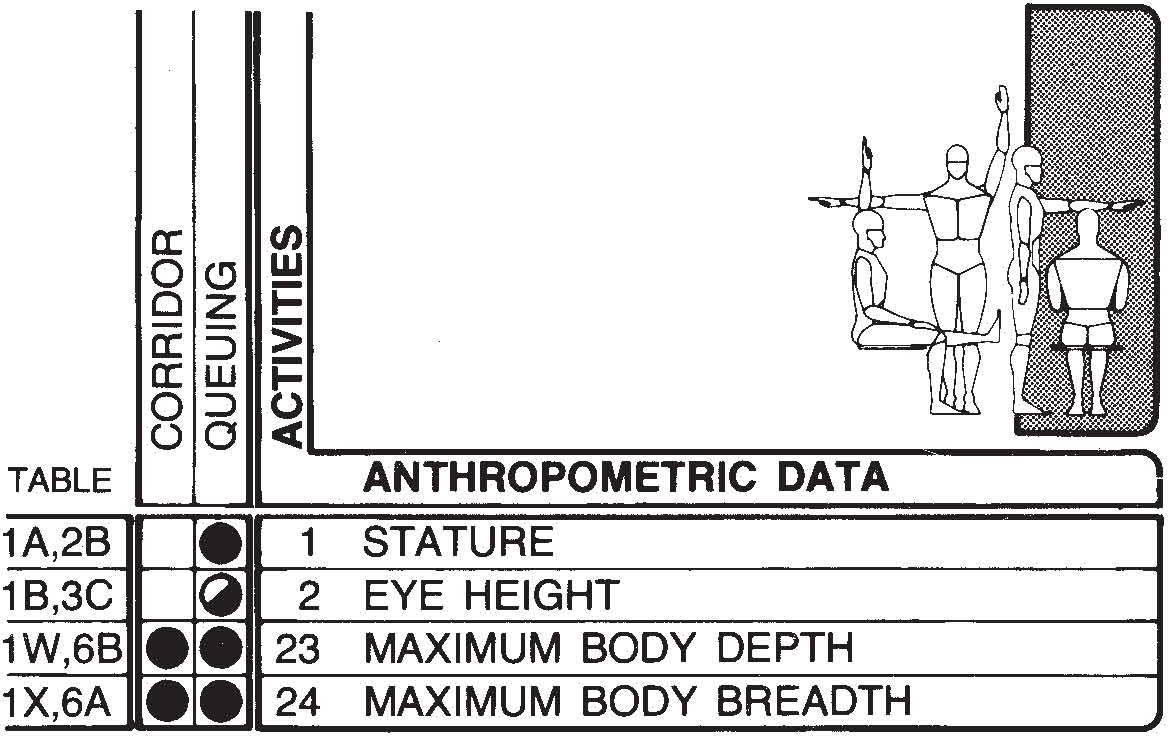

Horizontal circulation spaces may include typical corridors found in public buildings ranging from 60- to 144-in, or 152.4- to 365.8-cm wide, lobbies, pedestrian promenades, plazas in enclosed shopping malls, and large circulation and concourse areas in transportation terminals. Planning these spaces can be a fairly sophisticated and complicated matter, involving such factors as flow volume (usually expressed as pedestrians per foot width of walkway per minute), time and distance headways, walking speeds, queue lengths. The services of a traffic engineer or pedestrian planning specialist are usually required to properly design the larger spaces. Part of the process, no matter how sophisticated, is consideration of the human factor of body size and dimension. In addition some insight into physiological and psychological factors is also required. The intent here is to focus primarily on the anthropometric aspects, with the knowledge that this constitutes but a small part of the entire design process. The drawings on the following pages deal primarily with the human body and its maximum body depth and breadth as the basic increment of measurement. This incremental unit is then applied within the context of queuing situations and corridors.
In dealing with pedestrian locomotion, the human body must serve as the basic increment of measure and the larger-size person as the model in establishing clearance dimensions. If such clearances accommodate larger people, they obviously can accommodate those of smaller body size. The preceding diagram shows three views of the human figure, including critical 95th percentile dimensions of the three anthropometric measurements. In establishing breadth and depth dimensions, an allowance of 3 in, or 7.6 cm, for garments, including heavy outer winter clothing, was used. The breadth dimension assumes that the clothing consists of six layers. Accordingly, the aggregate allowance of 3 in is assumed to be equally distributed: one layer on the inside and outside surface of both arms and one layer on each side of the torso. The overall dimension so calculated is 28.8 in, or 65.5 cm. Heretofore, the generally accepted measurement was 22 in, or 55.9 cm, presumably based on the shoulder breadth of an average person. The authors contend that this is not a valid figure, since the critical anthropometric measurement to be utilized should be body breadth, not shoulder breadth and “average” data do not accommodate the majority of the population.
The following diagram and chart should also prove useful in the design of circulation spaces. They have been adapted from a study of pedestrian movement and queuing by Dr. John Fruin to establish relative levels of service based on pedestrian density. The basic unit is the human body, which is envisioned as a so-called body ellipse of 18 by 24 in, or 45.6 by 61 cm.


*Chart adapted from John J. Fruin, Pedestrian Planning and Design (New York: Metropolitan Association of Urban Designers and Environmental Planners, 1971).
The drawing above illustrates the two zones involved in walking. The pacing zone is the distance required to place one foot in front of the other. This distance varies with the individual due to the many psychological, physiological, and cultural factors involved, as well as sex, age, and physical condition. Most adults, however, have a pacing distance of between 24 and 36 in, or 61 and 91.4 cm. The sensory zone is the distance required for perception, evaluation, and reaction in sufficient time to avoid danger, all while the body is in motion. The multitude of human factors involved makes measurement of this distance extremely difficult. One indicator, however, might be the distance one person has to be behind the other to observe him from head to toe.
| in | cm | |
| A | 84 | 213.4 |
| B | 22–36 | 55.9–91.4 |
| C | 30–36 | 76.2–91.4 |
| D | 68 | 172.7 |
| E | 36–42 | 91.4–106.7 |
This is approximated to be about 84 in, or 213.4 cm, in a normal walking situation. In single- and double-lane corridors and passageways, clearances of 36 and 68 in, or 91.4 and 172.7 cm, respectively, are suggested. A 30-in, or 76.2-cm, minimum is suggested for a single lane with no physical obstructions on either side.
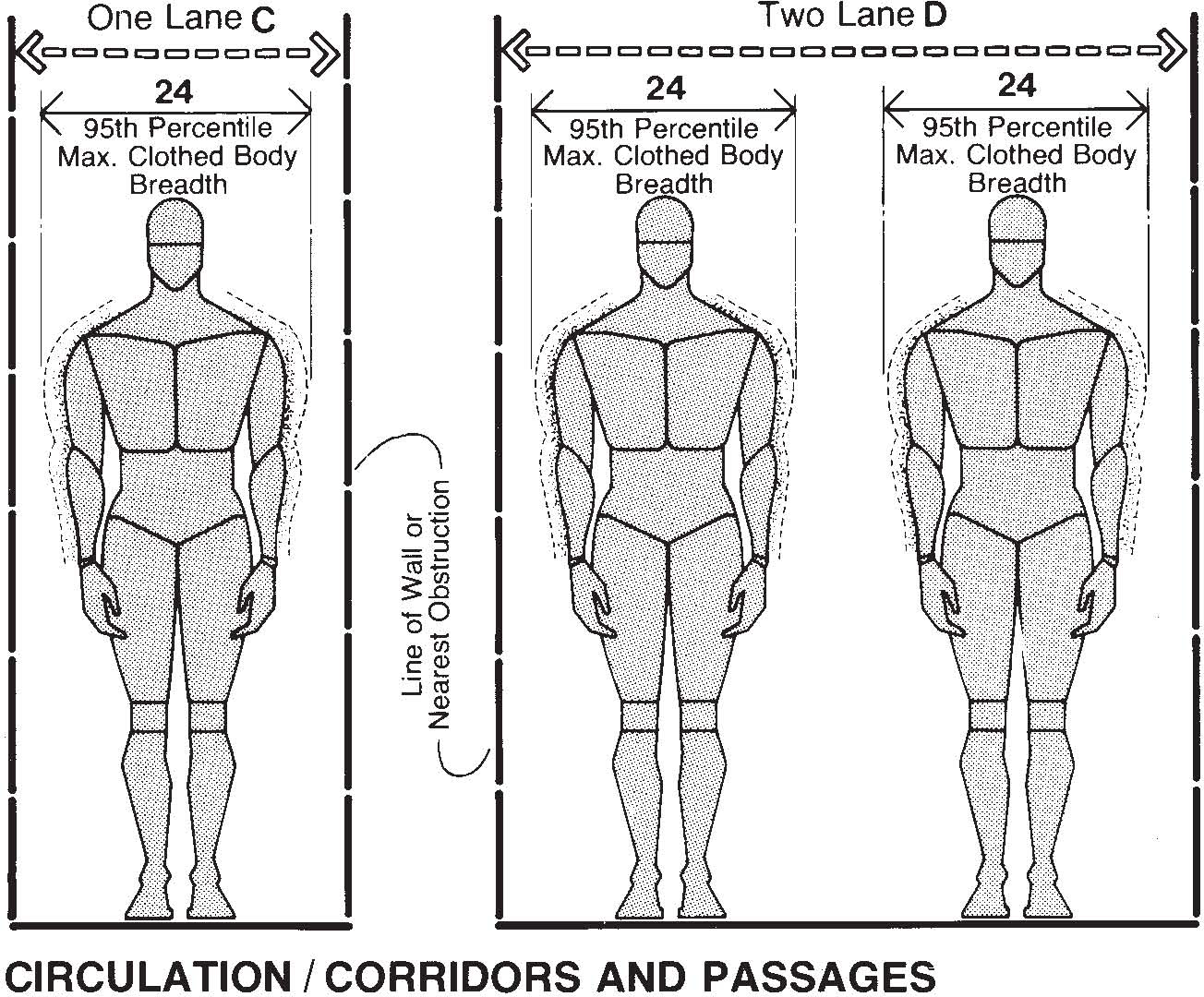

If carrying items or pushing a small cart is involved, the 36-in minimum should still be used. The double-lane clearance allows for two people abreast to circulate comfortably without body contact. The following drawing suggests the amount of space occupied by people carrying various types of hand luggage.


The purpose of the drawing shown above is to provide some idea of the physical relationship between human dimension and corridor width in terms of the number of lanes that can be accommodated. The row with three persons abreast is based on 95th percentile maximum clothed body breadth, while the row with four abreast is based on 5th percentile data. The corridor width was arbitrarily selected as 96 in, or 243.8 cm. The drawing should not be taken literally. The statistical likelihood of having the lineup of body sizes shown, at any single point in time, would be remote unless the space was originally intended to serve a specific user population of larger or smaller body size. Moreover, the 24-in, or 61-cm, lane with a 1.6-in clearance is obviously not intended as a standard.
| in | cm | |
| A | 4.5 | 11.4 |
| B | 32 | 81.3 |
| C | 1.6 | 4.1 |
| D | 24 | 61.0 |
| E | 96 | 243.8 |
| F | 30 | 76.2 |
| G | 36 | 91.4 |
| H | 120 | 304.8 |
The following drawing is intended to provide some insight into relative densities possible within a 120-in, or 308.4-cm, queue. Lane A shows as many people lined up as possible, with no regard for comfort or body contact. When an allowance for clothing is added to the maximum body breadth, the people in lane A would be pressed tightly together, violating all notions of personal space and comfort. Lanes B and C show the number of people that could be lined up, based on the densities of 3 and 7 sq ft, or .28 and .65 sq m per person, respectively.

![]() The previous drawing indicates the impact of a wheelchair-bound person on the same queue shown on this page. The following drawing indicates corridor width clearances necessary to accommodate wheelchair circulation. Full two-way passage requires 60 in, or 152.4 cm, to allow two wheelchairs to pass side by side. Clearance for a single wheelchair is 36 in, or 91.4 cm. A 54-in, or 137.2-cm, corridor will allow an able-bodied individual to walk along side or pass a wheelchair-bound person. Ideally, rest stops should be provided where corridor lengths are particularly long. These may be in the form of properly designed alcoves along the circulation path; rest room lounges or reception areas may be substituted if reasonably located. Maximum distance between rest room stops should be about 100 ft, or 30.5 m. Provisions for wheelchair turning should also be considered. A full 360° turn can be negotiated within a 60-in, or 152.4-cm, diameter circle.
The previous drawing indicates the impact of a wheelchair-bound person on the same queue shown on this page. The following drawing indicates corridor width clearances necessary to accommodate wheelchair circulation. Full two-way passage requires 60 in, or 152.4 cm, to allow two wheelchairs to pass side by side. Clearance for a single wheelchair is 36 in, or 91.4 cm. A 54-in, or 137.2-cm, corridor will allow an able-bodied individual to walk along side or pass a wheelchair-bound person. Ideally, rest stops should be provided where corridor lengths are particularly long. These may be in the form of properly designed alcoves along the circulation path; rest room lounges or reception areas may be substituted if reasonably located. Maximum distance between rest room stops should be about 100 ft, or 30.5 m. Provisions for wheelchair turning should also be considered. A full 360° turn can be negotiated within a 60-in, or 152.4-cm, diameter circle.


| in | cm | |
| A | 30 | 76.2 |
| B | 24 | 61.0 |
| C | 36 | 91.4 |
| D | 120 | 304.8 |
| E | 54 | 137.2 |
| F | 60 | 152.4 |

![]() The drawing shown above indicates that a 60-in, or 152.4-cm, clearance is necessary for a person on crutches to walk along side or pass a person in a wheelchair. A 42-in, or 106.7-cm, clearance is needed to accommodate a person standing sideways, while allowing a wheelchair-bound person to pass. The following drawings indicate the clearances necessary to accommodate a wheelchair in spaces where a series of two doors are involved. One drawing illustrates a situation where the two doors are in a row and the other where the doors are at right angles. A clearance of 84 in, or 213.4 cm, is necessary to allow the wheelchair to clear the first door as it swings shut. Since the length of the wheelchair is 42 in, or 106.7 cm, the 84-in dimension would allow for a door as wide as 36 in, or 91.4 cm, and an additional clearance of 6 in, or 15.2 cm, to spare. The 12-in, or 30.5-cm, minimum clearance on either side of the door allows enough maneuvering room for the wheelchair to approach the door at a slight angle and a person to grasp the door knob or pull and then back away. This is helpful when approaching the door from the in-swing side. When the doors are located at right angles to each other, it is essential that adequate space be provided to avoid interference between the two doors.
The drawing shown above indicates that a 60-in, or 152.4-cm, clearance is necessary for a person on crutches to walk along side or pass a person in a wheelchair. A 42-in, or 106.7-cm, clearance is needed to accommodate a person standing sideways, while allowing a wheelchair-bound person to pass. The following drawings indicate the clearances necessary to accommodate a wheelchair in spaces where a series of two doors are involved. One drawing illustrates a situation where the two doors are in a row and the other where the doors are at right angles. A clearance of 84 in, or 213.4 cm, is necessary to allow the wheelchair to clear the first door as it swings shut. Since the length of the wheelchair is 42 in, or 106.7 cm, the 84-in dimension would allow for a door as wide as 36 in, or 91.4 cm, and an additional clearance of 6 in, or 15.2 cm, to spare. The 12-in, or 30.5-cm, minimum clearance on either side of the door allows enough maneuvering room for the wheelchair to approach the door at a slight angle and a person to grasp the door knob or pull and then back away. This is helpful when approaching the door from the in-swing side. When the doors are located at right angles to each other, it is essential that adequate space be provided to avoid interference between the two doors.
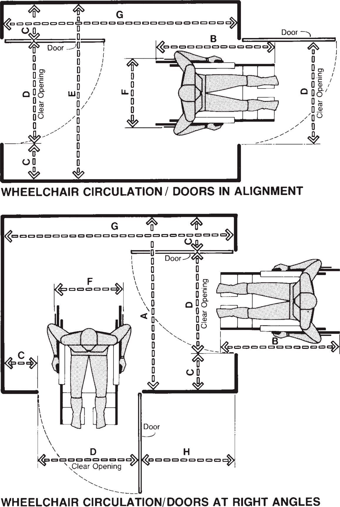

| in | cm | |
| A | 60 | 152.4 |
| B | 42 | 106.7 |
| C | 12 min. | 30.5 min. |
| D | 32 | 81.3 |
| E | 56 min. | 142.2 min. |
| F | 25 | 63.5 |
| G | 84 | 213.4 |
| H | 36 min. | 91.4 min. |


No public space can function without adequate vertical circulation systems. If these systems are not designed with human body size in mind, however, the efficiency and use of these systems are diminished. Moreover, the personal safety of the user is endangered. Nowhere is this more critical than in stair design. Both the width of the stair and the tread/riser relationship must reflect the human dimension. For stair width, most prevailing standards and guidelines directly or indirectly employ a unit of measurement of 22 in, or 55.9 cm, which purportedly represents the width of a so-called average person, a basic contention with which the authors disagree and which will be explored in the drawings and text on the following pages. This 22-in increment, however, is used as a basis for establishing lane width and has been in use and unchallenged for at least 25 years.
Tread/riser relationships are also based on assorted rules of thumb and formulas, many of which are in conflict with each other. One such formula, over 400 years old, is incorporated into the building code of the city of New York. That these formulas produce some kind of generally reasonable design is not disputed. What should be questioned is the quality of that design. How does a 9.5-in, or 24.1-cm, tread, for example, accommodate a maximum shod foot length of 14 in, or 35.6 cm? How much contact surface does the design provide? How much human energy is consumed in ascending the stair? What percentage of the user population is accommodated? If the stair is to be used to evacuate the building in the event of fire, can we afford to accommodate any less than 100 percent of the users? Does the tread/riser relationship reflect the needs of elderly people? These questions must be answered if designers are to be responsive to the human factors involved. There is also no doubt that proper tread/riser proportion involves other considerations as well, such as human gait, sensory perception, age, sex. A “perfect” solution may not be possible in view of the nature of the problem, but something more than a rule of thumb is needed. The drawings on the following pages examine some of these conditions and suggest clearances and other dimensional data responsive to human dimension and body size and useful in establishing preliminary design assumptions. The matrix shown here indicates some of the more relevant anthropometric measurements to consider.
The drawing of the 48-in, or 121.9-cm, two-lane escalator is intended to illustrate that 48 in is inadequate to comfortably accommodate larger-sized people on the same tread. Moreover, the 40-in, or 101.6-cm, clearance at the bottom limits the user’s stance, thereby reducing body stability. Stair motion, body contact, and lack of stability, taken together, present a safety hazard. This may account for the fact that the presence of two people on the same tread is not a very frequent occurrence.
| in | cm | |
| A | 48 | 121.9 |
| B | 25.8 | 65.5 |
| C | 7.1 | 18.0 |
| D | 12.9 | 32.8 |
| E | 40 | 101.6 |
| F | 68 | 172.7 |
| G | 44 | 111.8 |
| H | 4.2 | 10.7 |
| I | 4.9 | 12.4 |
| J | 2 min. | 5.1 min. |
| K | 1.5 | 3.8 |
| L | 3.5 max. | 8.9 max. |
| M | 30–34 | 76.2–86.4 |
| N | 1.5 min. | 3.8 min. |
The authors contend that the standard 44-in, or 117.7-cm, stair width, based on two 22-in, or 55.9-cm, body increments, will not accommodate those of larger body size. The argument against the 22-in increment is presented in the text related to the first drawing in Section 8.1.


Rail clearance should accommodate the hand thickness of the larger user and handrail size, the inside grip diameter of the smaller user. Adding glove thickness to the data shown in the following drawing, a 2-in, or 5.1-cm, clearance and a 1.5-in, or 3.8-cm, rail diameter will accommodate most people.


The drawing above shows some basic dimensional data and suggests the viewing zones involved. Although the stair is nearly as old as the architectural discipline itself, relatively little research has been done and most code requirements are based on rules of thumb, some dating back to the 17th century. The tread-riser relationship is the most important consideration here.
The following drawings show the anthropometric relationship between shod foot length and tread depth. Ninety-five percent of users with heavy winter boots have a shod foot length of about 9 in, or 22.9 cm, or less. The 9.5-in, or 24.1-cm, tread presently in common use allows comfortable tread contact for only 5 percent of the users, while the foot of the larger user overhangs the tread by more than 5 in, or 12.7 cm—certainly a cause for concern, especially for old and physically disabled people.


| in | cm | |
| A | 30–34 | 76.2–86.4 |
| B | 84 min. | 213.4 min. |
| C | 14.3 | 36.3 |
| D | 12.9 | 32.8 |
| E | 0.3 | 0.6 |
| F | 9.1 | 23.1 |
| G | 9.5 | 24.1 |
| H | 3.7 | 9.3 |
| I | 5 | 12.7 |
| J | 0.5 | 1.3 |
| K | 0.1 | 0.3 |
| L | 1.3 | 3.2 |
| M | 3.9 | 9.9 |
| N | 5.3 | 13.5 |
| O | 7.5 | 19.1 |
| P | 11.4 | 29.0 |
| Q | 2 | 5.1 |
| R | 3.4 | 8.6 |
| S | 6.7 | 17.0 |
| T | 0.5–1 | 1.3–2.5 |
| U | 11.8 | 29.8 |
| V | 1.6–2.1 | 4.1–5.3 |
| W | 3–3.5 | 7.6–8.9 |
| X | 6.8 | 17.1 |

![]() Vertical circulation systems must be responsive to the needs of people confined to wheelchairs as well as to those of able-bodied people. Corridor and lobby call buttons should be located 54 in, or 137.2 cm, above the floor. Emergency controls should be arranged so that the lowest button is a minimum of 30 in, or 76.2 cm, above the cab floor and the highest button a maximum of 48 in, or 121.9 cm, above the cab floor. Emergency buttons should be grouped together at the bottom of the panel. The center line of a telephone should be a maximum of 48 in above the cab floor and the height at the top of the handrail should be located between 32 and 34 in, or 81.3 and 86.4 cm, above the cab floor.
Vertical circulation systems must be responsive to the needs of people confined to wheelchairs as well as to those of able-bodied people. Corridor and lobby call buttons should be located 54 in, or 137.2 cm, above the floor. Emergency controls should be arranged so that the lowest button is a minimum of 30 in, or 76.2 cm, above the cab floor and the highest button a maximum of 48 in, or 121.9 cm, above the cab floor. Emergency buttons should be grouped together at the bottom of the panel. The center line of a telephone should be a maximum of 48 in above the cab floor and the height at the top of the handrail should be located between 32 and 34 in, or 81.3 and 86.4 cm, above the cab floor.
| in | cm | |
| A | 18 | 45.7 |
| B | 48 min. | 121.9 min. |
| C | 54 max. | 137.2 max. |
| D | 30 | 76.2 |
| E | 42 min. | 106.7 min. |
| F | 72 min. | 182.9 min. |
| G | 12–18 | 30.5–45.7 |
| H | 18–20 | 45.7–50.8 |
| I | 33–34 | 83.8–86.4 |


Ramps are also an important factor in providing accessibility of buildings to handicapped people. Most regulations and guidelines insist on a maximum gradient of one unit of height for every twelve units of length and a maximum horizontal distance of 30 ft, or 9 m, without a horizontal landing of at least 42 in, or 106.7 cm. Landings should be provided at all changes in ramp direction and at entrances and exits. Platform lengths should provide at least 42-in clearance from any door swing into the ramp. Where the door does not swing into the ramp, the platform should extend a minimum of 24 in, or 61 cm, past the latch side of the door.



The term “public” toilet facility is to a large degree generic since it is quite possible and proper to create subclassifications depending on the user population it is intended to serve. A public facility located in an air, bus, or rail terminal, for example, would serve a transient user as opposed to a similar facility provided for the convenience of the workers in a large midtown office building. These facilities may have much and at the same time very little in common. To varying degrees they both have peak periods of use. The anthropometric considerations, particularly during these peak periods, are also quite similar. Since the intent is to focus on human dimension as it relates to interior space, no attempt has been made to establish a classification system or to comment on the inherent design of the fixtures themselves.
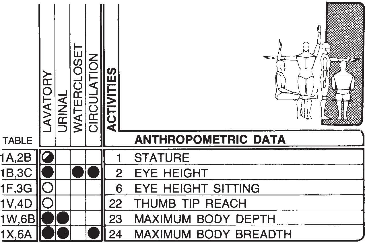
What is painfully obvious in the drawings on the following pages is that most public toilet facility designs appear to be totally insensitive to human dimension and body size. Most designs crowd the designated number of fixtures required by local agencies in the least amount of floor space possible. The fact is that the spacing of fixtures, particularly urinals (19 and 21 in, or 48.3 and 53.6 cm, on center is not uncommon), does not accommodate the majority of users. Published anthropometric data, for example, indicates that only 5 percent of a sample population measured has a maximum body breadth dimension of 18.8 in, or 47. 8 cm, or less. When a clothing allowance is added, it becomes obvious that a 19- or a 21-in, or a 48.3- or a 53.6-cm, spacing would make it almost impossible for people to use the urinals without coming into body contact with each other. The same type of situation exists with regard to lavatory fixtures. When one considers the hidden dimensions, body buffer zones, privacy factor, such spacing becomes totally unacceptable. For this reason it is not uncommon in public bathrooms to observe situations of extreme crowding and congestion with people queued up waiting to use the facilities while at the same time every other fixture may be unoccupied. The drawings on the following pages examine these conditions and such clearances and other dimensional data more responsive to human body size and dimension, while the matrix above suggests some of the more important anthropometric measurements to consider in the design of public bathrooms.

![]() Stall urinals are available for battery installations on 21-in, or 53.3-cm, centers. The authors contend that such spacing will not properly accommodate the majority of users. The larger-sized person has a maximum clothed body breadth dimension of almost 26 in, or 66 cm. Postures assumed while urinating, in addition to the space taken up by partially opened garments, will increase this dimension even more. Given the anthropometric realities and consideration of personal space, a 32-in, or 81.3-cm, spacing is more responsive to human factors. The stall partition should extend 8 to 10 in, or 20.3 to 25.4 cm, beyond the face of the urinal, and an activity zone of 18 in, or 45.7 cm, in front of the fixture should be assumed. A circulation zone of 54 in, or 137.2 cm, will allow for pedestrian and wheelchair traffic. Urinal stalls for wheelchair users should be a minimum of 36 in, or 91.4 cm, wide for proper access. Minimum toilet stall dimensions required for a front transfer approach by the wheelchair user are 42 by 72 in, or 106.7 by 182.9 cm. A wheelchair clearance zone should be provided in front of the stall.
Stall urinals are available for battery installations on 21-in, or 53.3-cm, centers. The authors contend that such spacing will not properly accommodate the majority of users. The larger-sized person has a maximum clothed body breadth dimension of almost 26 in, or 66 cm. Postures assumed while urinating, in addition to the space taken up by partially opened garments, will increase this dimension even more. Given the anthropometric realities and consideration of personal space, a 32-in, or 81.3-cm, spacing is more responsive to human factors. The stall partition should extend 8 to 10 in, or 20.3 to 25.4 cm, beyond the face of the urinal, and an activity zone of 18 in, or 45.7 cm, in front of the fixture should be assumed. A circulation zone of 54 in, or 137.2 cm, will allow for pedestrian and wheelchair traffic. Urinal stalls for wheelchair users should be a minimum of 36 in, or 91.4 cm, wide for proper access. Minimum toilet stall dimensions required for a front transfer approach by the wheelchair user are 42 by 72 in, or 106.7 by 182.9 cm. A wheelchair clearance zone should be provided in front of the stall.


| in | cm | |
| A | 32 | 81.3 |
| B | 54 | 137.2 |
| C | 18 | 45.7 |
| D | 8–10 | 20.3–25.4 |
| E | 14 min. | 35.6 min. |
| F | 36 min. | 91.4 min. |
| G | 42 | 106.7 |
| H | 25 | 63.5 |
| I | 19 | 48.3 |
| J | 17 max. | 43.2 max. |
| K | 12 min. | 30.5 min. |
| L | 14 max. | 35.6 max. |
| M | 48 | 121.9 |
| N | 18 min. | 45.7 min. |
| O | 12 | 30.5 |
| P | 42 min. | 106.7 min. |
| Q | 1.5 min. | 3.8 min. |
| R | 72 min. | 182.9 min. |

![]() Rather than the front transfer approach discussed on the preceding page, a more comfortable access to the W.C. for the wheelchair user is the side approach transfer. The drawing above shows the minimum compartment dimensions for such a transfer: 66 by 72 in, or 167.6 by 182.9 cm.
Rather than the front transfer approach discussed on the preceding page, a more comfortable access to the W.C. for the wheelchair user is the side approach transfer. The drawing above shows the minimum compartment dimensions for such a transfer: 66 by 72 in, or 167.6 by 182.9 cm.
| in | cm | |
| A | 72 min. | 182.9 min. |
| B | 32 | 81.3 |
| C | 66 min. | 167.6 min. |
| D | 18 min. | 45.7 min. |
| E | 18 | 45.7 |
| F | 1.5 min. | 3.8 min. |
| G | 36 | 91.4 |
| H | 54 min. | 137.2 min. |
| I | 58 | 147.3 |
| J | 12 | 30.5 |
| K | 30 max. | 76.2 max. |
| L | 10 | 25.4 |
| M | 14–15 | 35.6–38.1 |
To appreciate the problems faced by those confined to a wheelchair in gaining access to rest room facilities, it is necessary to understand something of the transfer process. The following drawing attempts to break down that process into four basic movements; techniques will vary from user to user, but the process is essentially as illustrated.


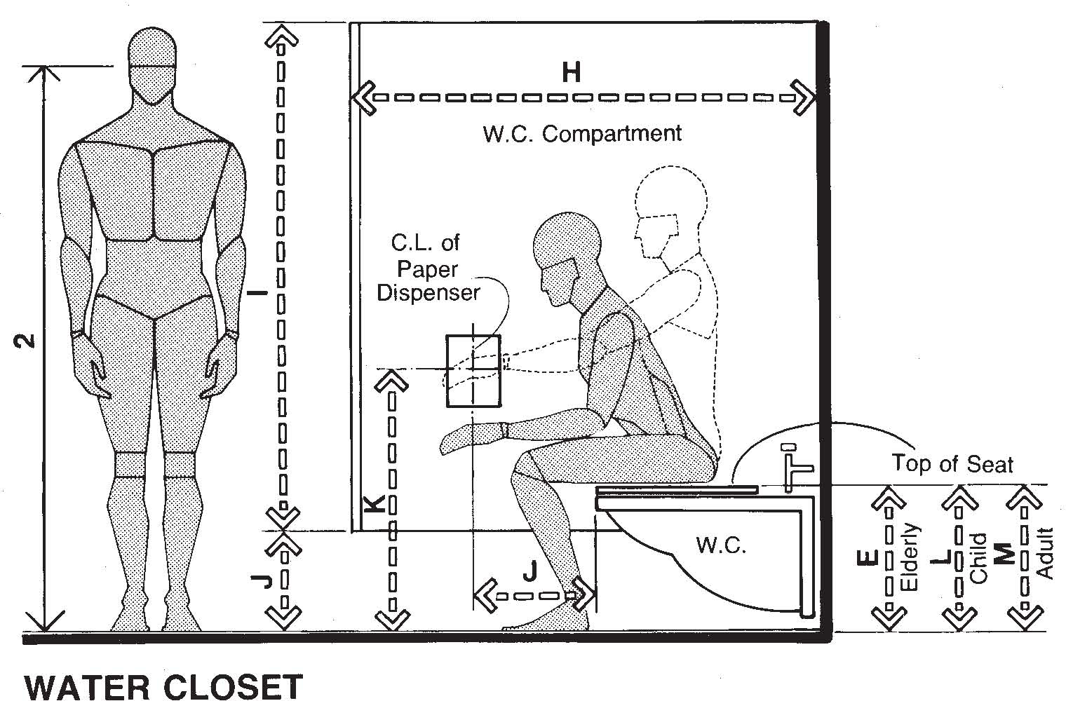
The next drawing shows some of the basic heights and clearances to be considered in a conventional W.C. compartment. Note that different heights for the W.C. are suggested in response to the anthropometric requirements of elderly people and children.


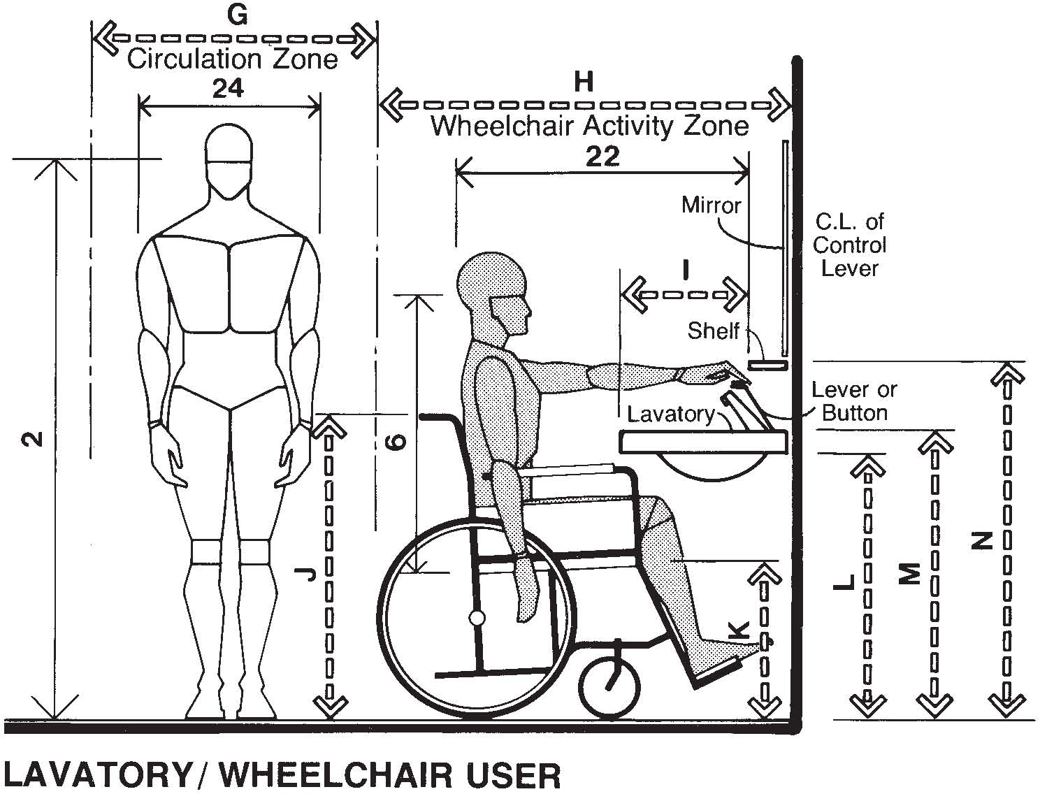
![]() Lavatories, like urinals, are all too often located too close to each other. The result is an installation that may save floor space and may conform to the code in terms of quantity of fixtures, but simply does not permit the user comfortable access. It has been stated elsewhere that the larger-sized person has a maximum clothed body breadth dimension of almost 26 in, or 66 cm, which already exceeds the width of most lavatory models usually specified for public rest rooms. The body movements involved in the washing and grooming process increase the space occupied by the user even more. Unless adequate space is provided, body contact with the adjacent user will occur. A 32-in, or 81.3-cm, spacing as shown should provide for comfortable use of the fixtures. An activity zone of 18 in, or 45.7 cm, in front of the fixtures should be assumed. A circulation zone of 54 in, or 137.2 cm, is the minimum dimension that will allow for both wheelchair and pedestrian traffic.
Lavatories, like urinals, are all too often located too close to each other. The result is an installation that may save floor space and may conform to the code in terms of quantity of fixtures, but simply does not permit the user comfortable access. It has been stated elsewhere that the larger-sized person has a maximum clothed body breadth dimension of almost 26 in, or 66 cm, which already exceeds the width of most lavatory models usually specified for public rest rooms. The body movements involved in the washing and grooming process increase the space occupied by the user even more. Unless adequate space is provided, body contact with the adjacent user will occur. A 32-in, or 81.3-cm, spacing as shown should provide for comfortable use of the fixtures. An activity zone of 18 in, or 45.7 cm, in front of the fixtures should be assumed. A circulation zone of 54 in, or 137.2 cm, is the minimum dimension that will allow for both wheelchair and pedestrian traffic.
| in | cm | |
| A | 42 | 106.7 |
| B | 25 | 63.5 |
| C | 32 | 81.3 |
| D | 18 | 45.7 |
| E | 54 | 137.2 |
| F | 72 | 182.9 |
| G | 30 min. | 76.2 min. |
| H | 48 | 121.9 |
| I | 18 max. | 45.7 max. |
| J | 36 | 91.4 |
| K | 19 | 48.3 |
| L | 30 min. | 76.2 min. |
| M | 34 max. | 86.4 max. |
| N | 40 max. | 101.6 max. |
The following drawing indicates some of the basic clearances and heights required to make the lavatory accessible to the wheelchair user.

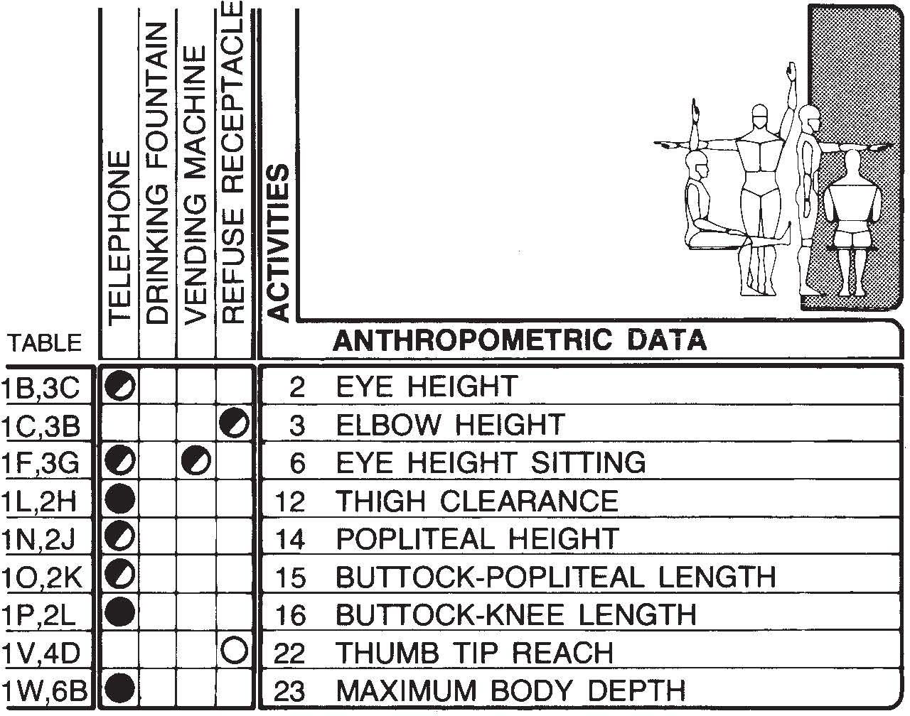

Public convenience facilities must be provided in the design of public spaces. The type and quantity of such facilities will vary depending on the size and nature of the public space involved. They may range from a modest but strategically placed ash urn to a battery of public telephones. It is essential that these facilities be accessible to able-bodied people as well as to semiambulant, elderly, and chair-bound people. The quality of interface between the user and these facilities requires a knowledge of human dimension. A public phone, for example, does a chair-bound user no good if he can’t reach the coin slot. The drawings on the following pages illustrate some typical situations showing the human body in relation to a range of some basic public convenience facilities encountered in public spaces. The anthropometric measurements of major concern in the design and placement of these facilities are indicated in the matrix shown here.

![]() For public telephones to be accessible to wheelchair users, dial, coin slot, and head set should not be more than 48 in, or 121.9 cm, above the floor. It is also desirable that adjustable volume control be provided with the headset to assist those with hearing disabilities. Tactile and visual instructions should be provided for those users with sight disabilities. Wall-mounted units should have adequate space for wheelchair approach parallel to the front face of the equipment. Where shelves are provided below the telephone unit, a clearance of at least 29 in, or 73.7 cm, from the floor to the underside of the lowest part of the shelf should be provided.
For public telephones to be accessible to wheelchair users, dial, coin slot, and head set should not be more than 48 in, or 121.9 cm, above the floor. It is also desirable that adjustable volume control be provided with the headset to assist those with hearing disabilities. Tactile and visual instructions should be provided for those users with sight disabilities. Wall-mounted units should have adequate space for wheelchair approach parallel to the front face of the equipment. Where shelves are provided below the telephone unit, a clearance of at least 29 in, or 73.7 cm, from the floor to the underside of the lowest part of the shelf should be provided.


If booths are provided for the chair-bound, at least 42 in, or 106.7 cm, of clear floor space should be provided between walls. The telephone unit should be mounted on the side wall and a 32-in, or 81.3-cm, clear door opening should be provided.
| in | cm | |
| A | 48 | 121.9 |
| B | 48 max. | 121.9 max. |
| C | 13–20 | 33.0–50.8 |
| D | 36 | 91.4 |
| E | 8–12 | 20.3–30.5 |
| F | 19 | 48.3 |
| G | 29 min. | 73.7 min. |
| H | 32 max. | 81.3 max. |

![]() The drawings shown above indicate some of the key dimensions for a wall-mounted public telephone. The installation intended to serve the seated user should comfortably serve a large number of standing users as well.
The drawings shown above indicate some of the key dimensions for a wall-mounted public telephone. The installation intended to serve the seated user should comfortably serve a large number of standing users as well.
The following drawing shows the critical measurements necessary so that a drinking fountain can be accessible to both handicapped and able-bodied people.


A distance of 30 in, or 76.2 cm, from the rim to the floor will make the fountain accessible to both wheelchair users and children. Some codes allow the use of a conventional drinking fountain to serve the wheelchair user if it does not exceed 36 in, or 91.4 cm, in height. The authors suggest that the 30-in height be used and, if necessary, a maximum height of 34 in, or 86.4 cm, not be exceeded. It is recommended also that hand-operated controls or combined hand-and-foot controls be used.
| in | cm | |
| A | 24 | 61.0 |
| B | 25 | 63.5 |
| C | 12 | 30.5 |
| D | 30 | 76.2 |
| E | 34 | 86.4 |
| F | 18 | 45.7 |
| G | 13–20 | 33.0–50.8 |
| H | 43 | 109.2 |
| I | 37 | 94.0 |
| J | 32.5 | 82.6 |
| K | 36 | 91.4 |
| L | 36 max. | 91.4 max. |
| M | 8 min. | 20.3 min. |
| N | 19 | 48.3 |

![]() The drawings shown above indicate recommended heights for refuse receptacles to serve chairbound and semiambulant users. Provisions for a support can be extremely helpful.
The drawings shown above indicate recommended heights for refuse receptacles to serve chairbound and semiambulant users. Provisions for a support can be extremely helpful.
The following drawings show a floor-type and wall-hung or shelf-type vending machine installation. Proper location of operating controls and coin slots is essential if the machines are to serve handicapped as well as able-bodied people.


To be accessible to the chairbound user, the controls should be no less than 24 in, or 61.0 cm, nor more than 48 in, or 121.9 cm, above the floor. An activity zone of 42 in, or 106.7 cm, should be assumed in front of the machine for a person in a wheelchair. Where purely mechanical pull devices are used, they should require a minimal amount of force for operation.
| in | cm | |
| A | 19 | 48.3 |
| B | 25 | 63.5 |
| C | 40 | 101.6 |
| D | 48–54 | 121.9–137.2 |
| E | 30 | 76.2 |
| F | 24 min. | 61.0 min. |
| G | 48 max. | 121.9 max. |
| H | 48 | 121.9 |
| I | 36 max. | 91.4 max. |