
Today, electricity is well known and appears all around us from the lighting in our houses to the computing in our personal computers. All of these are powered by complex circuits. In this chapter, we will study the basics of simple direct current circuits.
Picture a piece of metal wire. Within the metal, electrons are zooming around at speeds of about a million meters per second in random directions, colliding with other electrons and positive ions in the lattice. This constitutes charge in motion, but it doesn’t constitute net movement of charge because the electrons move randomly. If there’s no net movement of charge, there’s no current. However, if we were to create a potential difference between the ends of the wire, meaning if we set up an electric field, the electrons would experience an electric force, and they would start to drift through the wire. This is current. Although the electric field would travel through the wire at nearly the speed of light, the electrons themselves would still have to make their way through a crowd of atoms and other free electrons, so their drift speed, vd, would be relatively slow, on the order of a millimeter per second.
To measure the current, we have to measure how much charge crosses a plane per unit time. If an amount of charge of magnitude ΔQ crosses an imaginary plane in a time interval Δt, then the average current is

Because current is charge per unit time, it’s expressed in coulombs per second. One coulomb per second is an ampere (abbreviated A), or amp. So 1 C/s = 1 A.
Although the charge carriers that constitute the current within a metal are electrons, the direction of the current is taken to be the direction that positive charge carriers would move. (This is explicitly stated on the AP Physics 1 Exam.) So, if the conduction electrons drift to the right, we’d say the current points toward the left.
Let’s say we had a copper wire and a glass fiber that had the same length and cross-sectional area, and that we hooked up the ends of the metal wire to a source of potential difference and measured the resulting current. If we were to do the same thing with the glass fiber, the current would probably be too small to measure, but why? Well, the glass provided more resistance to the flow of charge. If the potential difference is V and the current is I, then the resistance is

This is known as Ohm’s Law. Notice for the same voltage if the current is large, the resistance is low, and if the current is small, then resistance is high. The Δ in the equation above is often omitted, but you should always assume that in this context, V = ΔV = potential difference, also called voltage.
Because resistance is voltage divided by current, it is expressed in volts per amp. One volt per amp is one ohm (Ω, omega). So, 1 V/A = 1 Ω.
Using R = V/I is the most common way to solve for resistance, but it can work only if the resistor is already connected to other elements in a circuit. What if someone just handed you a resistor and asked you to find its resistance? In that case, you would have to use an alternative formula.
R = ρL/A
In this formula, L is the length of the resistor, A is the cross-sectional area, and ρ is a property called resistivity. This is an intrinsic property of a given material (just like density) that measures how difficult it is for current to flow through it and would be given to you if a numerical value is ever needed on the test. Qualitatively, you can think of it as the opposite of conductance. Good conductors (e.g., metals) have low resistivity, and insulators (e.g., rubber) have high resistivity.
Now that we know how to measure current, the next question is, what causes it? Why does an electron drift through the circuit? One answer is to say that there’s an electric field inside the wire, and since negative charges move in the direction opposite to the electric field lines, electrons would drift opposite the electric field.
Another (equivalent) answer to the question is that there’s a potential difference (a voltage) between the ends of the wire. Positive charges naturally move from regions of higher potential to lower potential.
Voltage is what creates a current.
It is not uncommon to see the voltage that creates a current referred to as electromotive force (emf), since it is the cause that sets the charges into motion into a preferred direction. The voltage provided in a circuit is generally supplied by the battery.
An electric current is maintained when the terminals of a voltage source (a battery, for example) are connected by a conducting pathway, in what’s called a circuit. If the current always travels in the same direction through the pathway, it’s called a direct current.

The job of the voltage source is to provide a potential difference called an emf, or electromotive force, which drives the flow of charge. The emf isn’t really a force; it’s the work done per unit charge, and it’s measured in volts.
To try to imagine what’s happening in a circuit in which a steady-state current is maintained, let’s follow one of the charge carriers that’s drifting through the pathway. (Remember we’re pretending that the charge carriers are positive.) The charge is introduced by the positive terminal of the battery and enters the wire, where it’s pushed by the electric field. It encounters resistance, bumping into the relatively stationary atoms that make up the metal’s lattice and setting them into greater motion. So the electrical potential energy that the charge had when it left the battery is turning into heat. By the time the charge reaches the negative terminal, all of its original electrical potential energy is lost. In order to keep the current going, the voltage source must do positive work on the charge, forcing it to move from the negative terminal toward the positive terminal. The charge is now ready to make another journey around the circuit.
When a carrier of positive charge q drops by an amount V in potential, it loses potential energy in the amount qV. If this happens in time t, then the rate at which this energy is transformed is equal to (qV)/t = (q/t)V. But q/t is equal to the current, I, so the rate at which electrical energy is transferred is given by the equation
P = IV
This equation works for the power delivered by a battery to the circuit as well as for resistors. The power dissipated in a resistor, as electrical potential energy is turned into heat, is given by P = IV, but, because of the relationship V = IR, we can express this in two other ways:

or

Resistors become hot when current passes through them.
We will now develop a way of specifying the current, voltage, and power associated with each element in a circuit. Our circuits will contain three basic elements: batteries, resistors, and connecting wires. As we’ve seen, the resistance of an ordinary metal wire is negligible; resistance is provided by devices that control the current: resistors. All the resistance of the system is concentrated in the resistors, which are symbolized in a circuit diagram by this symbol:

Batteries are denoted by the symbol:
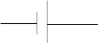
where the longer line represents the positive (higher potential) terminal, and the shorter line is the negative (lower potential) terminal. Sometimes a battery is denoted by more than one pair of such lines:

Here’s a simple circuit diagram:

The electric potential (V) of the battery is indicated, as is the resistance (R) of the resistor. Determining the current in this case is straightforward because there’s only one resistor. The equation V = IR gives us

Two common ways of combining resistors within a circuit is to place them either in series (one after the other),

or in parallel (that is, side-by-side):

In order to simplify the circuit, our goal is to find the equivalent resistance of combinations. Resistors are said to be in series if they all share the same current and if the total voltage drop across them is equal to the sum of the individual voltage drops.

In this case, then, if V denotes the voltage drop across the combination, we have

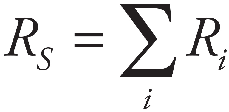
This idea can be applied to any number of resistors in series (not just two):
Resistors are said to be in parallel if they all share the same voltage drop, and the total current entering the combination is split among the resistors. Imagine that a current I enters the combination. It splits; some of the current, I1, would go through R1, and the remainder, I2, would go through R2.

So if V is the voltage drop across the combination, we have

This idea can be applied to any number of resistors in parallel (not just two): the reciprocal of the equivalent resistance for resistors in parallel is equal to the sum of the reciprocals of the individual resistances:

Example 1 Calculate the equivalent resistance for the following circuit:
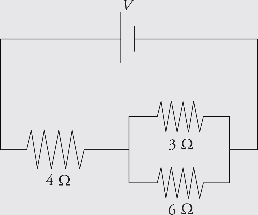
Solution. First, find the equivalent resistance of the two parallel resistors:

This resistance is in series with the 4 Ω resistor, so the overall equivalent resistance in the circuit is R = 4 Ω + 2 Ω = 6 Ω.
Example 2 Determine the current through each resistor, the voltage drop across each resistor, and the power given off (dissipated) as heat in each resistor of this circuit:
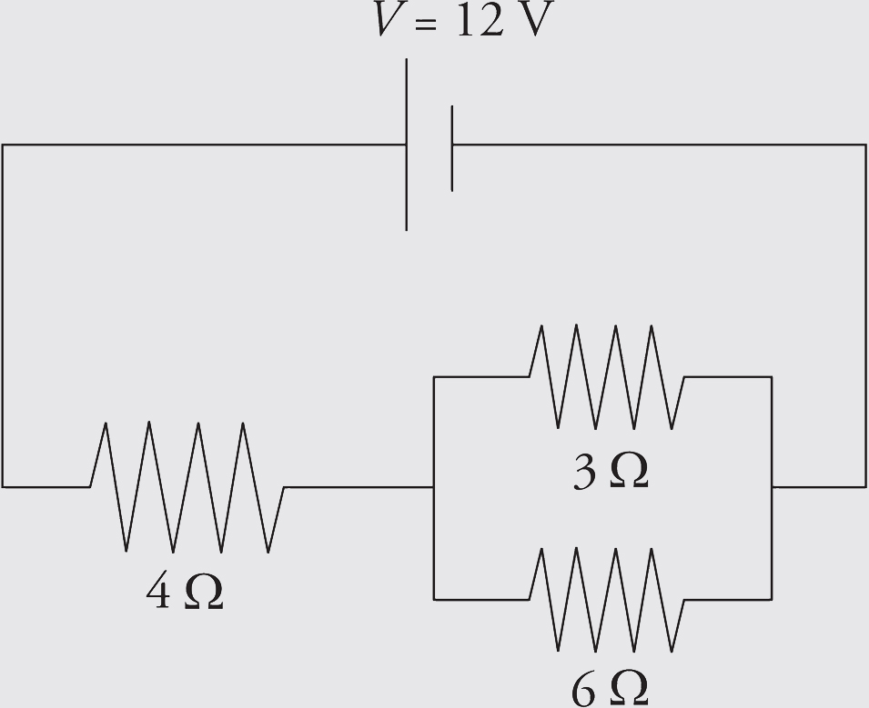
Solution. You might want to redraw the circuit each time we replace a combination of resistors by its equivalent resistance. From our work in the preceding example, we have

From diagram 3, which has just one resistor, we can figure out the current:

Now we can work our way back to the original circuit (diagram 1). In going from 3 to 2, we are going back to a series combination, and what do resistors in series share? That’s right, the same current. So, we take the current, I = 2 A, back to diagram 2. The current through each resistor in diagram 2 is 2 A.
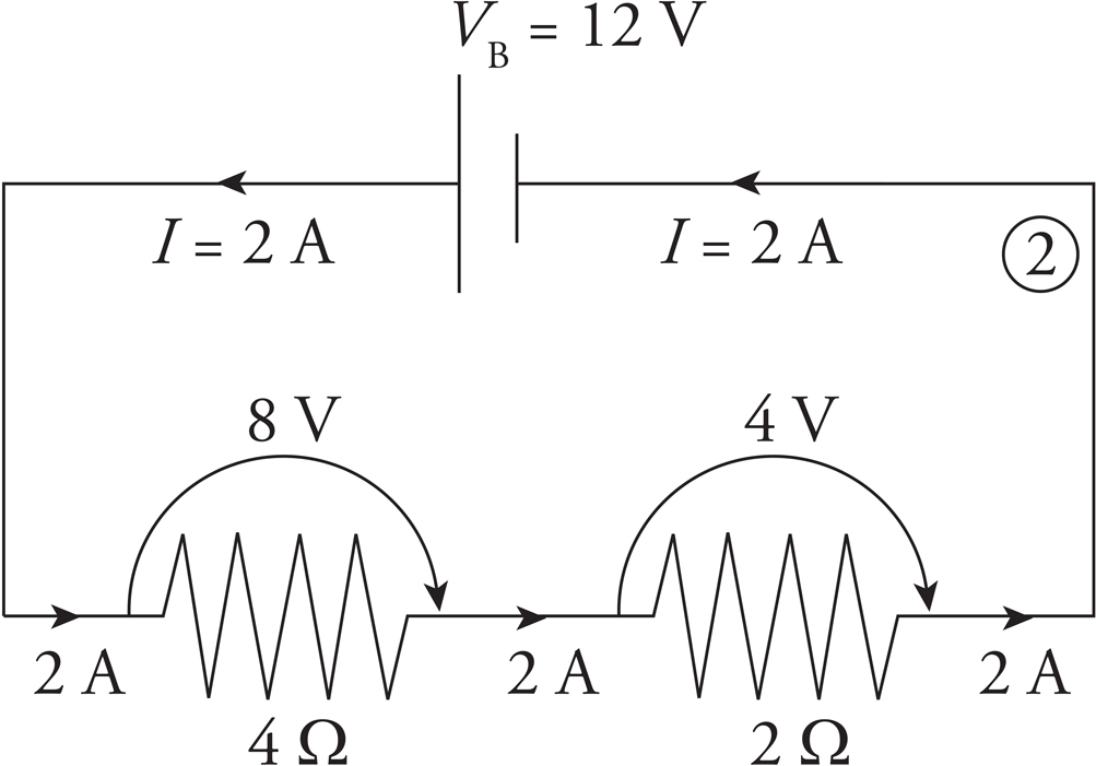
Since we know the current through each resistor, we can figure out the voltage drop across each resistor using the equation V = IR. The voltage drop across the 4 Ω resistor is (2 A)(4 Ω) = 8 V, and the voltage drop across the 2 Ω resistor is (2 A)(2 Ω) = 4 V. Notice that the total voltage drop across the two resistors is 8 V + 4 V = 12 V, which matches the emf of the battery.
Now for the last step! Going from diagram 2 back to diagram 1. Nothing needs to be done with the 4 Ω resistor; nothing about it changes in going from diagram 2 to 1, but the 2 Ω resistor in diagram 2 goes back to the parallel combination. And what do resistors in parallel share? The same voltage drop. So we take the voltage drop, V = 4 V, back to diagram 1. The voltage drop across each of the two parallel resistors in diagram 1 is 4 V.

Since we know the voltage drop across each resistor, we can figure out the current through each resistor by using the equation I = V/R. The current through the 3 Ω resistor is (4 V)/(3 Ω) =  A, and the current through the 6 Ω resistor is (4 V)/(6 Ω) =
  A. Note that the current entering the parallel combination (2 A) equals the total current passing through the individual resistors
  . Again, this was expected.
Finally, we will calculate the power dissipated as heat by each resistor. We can use any of the equivalent formulas: P = IV, P = I2R, or P = V2/R.
For the 4 Ω resistor: P = IV = (2 A)(8 V) = 16 W
For the 3 Ω resistor: P = IV = (A)(4 V) =  W
W
For the 6 Ω resistor: P = IV = (A)(4 V) =  W
W
So, the resistors are dissipating a total of

If the resistors are dissipating a total of 24 J every second, then they must be provided with that much power. This is easy to check: P = IV = (2 A)(12 V) = 24 W.
Example 3 A student has three 30 Ω resistors and an ideal 90 V battery. (A battery is ideal if it has a negligible internal resistance.) Compare the current drawn from—and the power supplied by—the battery when the resistors are arranged in parallel versus in series.
Solution. Resistors in series always provide an equivalent resistance that’s greater than any of the individual resistances, and resistors in parallel always provide an equivalent resistance that’s smaller than their individual resistances. So, hooking up the resistors in parallel will create the smallest resistance and draw the greatest total current:

In this case, the equivalent resistance is

and the total current is I = V/RP = (90 V)/(10 Ω) = 9 A. (You could verify that 3 A of current would flow in each of the three branches of the combination.) The power supplied by the battery will be P = IV = (9 A)(90 V) = 810 W.
If the resistors are in series, the equivalent resistance is RS = 30 Ω + 30 Ω + 30 Ω = 90 Ω, and the current drawn is only I = V/RS = (90 V)/(90 Ω) = 1 A. The power supplied by the battery in this case is just P = IV = (1 A)(90 V) = 90 W.
Example 4 The diagram below shows a point a at potential V = 20 V connected by a combination of resistors to a point (denoted G) that is grounded. The ground is considered to be at potential zero. If the potential at point a is maintained at 20 V, what is the current through R3?
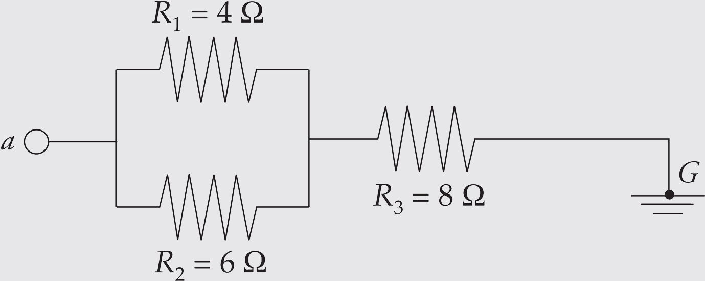
Solution. R1 and R2 are in parallel; their equivalent resistance is RP, where
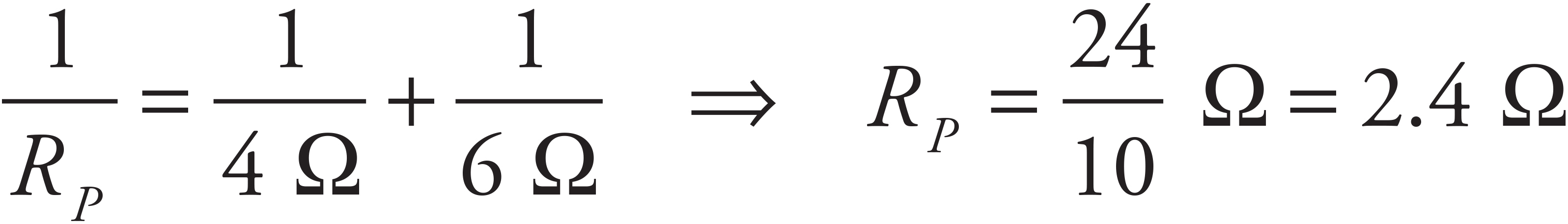
RP is in series with R3, so the equivalent resistance is
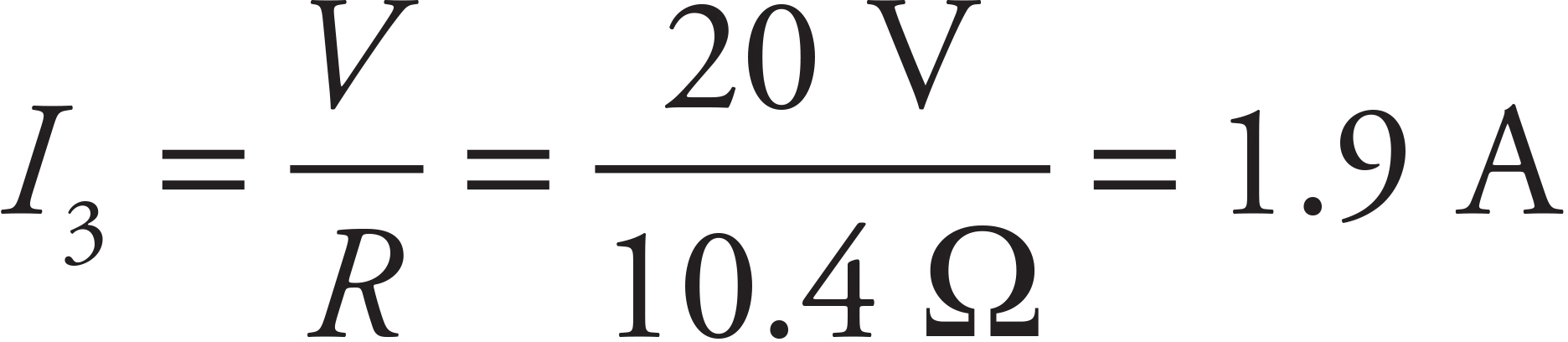
R = RP + R3 = (2.4 Ω) + (8 Ω) = 10.4 Ω
and the current that flows through R3 is
When the resistors in a circuit cannot be classified as either in series or in parallel, we need another method for analyzing the circuit. The rules of Gustav Kirchhoff (pronounced “Keer koff”) can be applied to any circuit.
Kirchhoff’s First Law, also known as both the Junction Rule and the Node Rule, reads as follows:
The total current that enters a junction must equal the total current that leaves the junction.

The current entering any junction is equal to the current leaving that junction: i2 + i3 = i1 + i4.
Kirchhoff’s Second Law is also known as the Loop Rule.
The sum of the potential differences (positive and negative) that traverse any closed loop in a circuit must be zero.
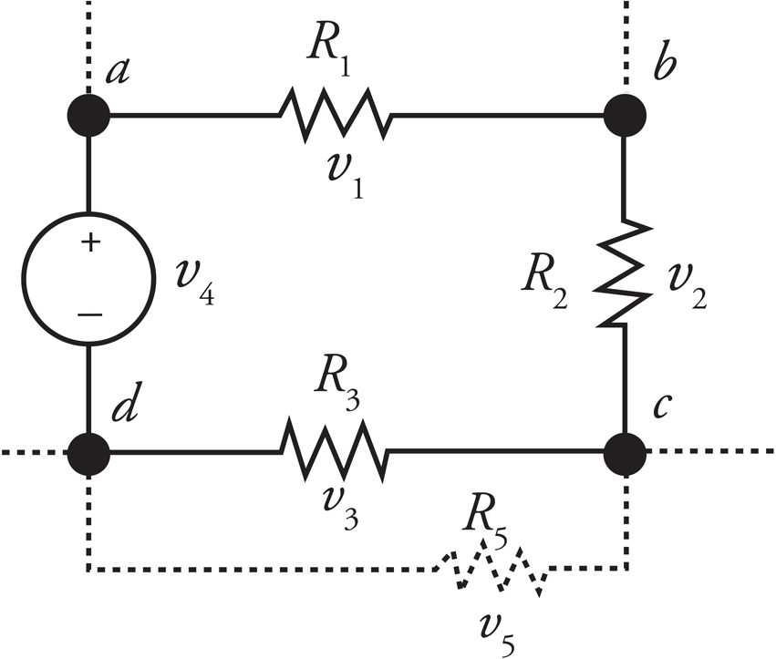
The sum of all voltages around the loop is equal to zero: v1 + v2 + v3 − v4 = 0.
The Loop Rule just says that, starting at any point, by the time we get back to that same point by following any closed loop, we have to be back to the same potential. Therefore, the total drop in potential must equal the total rise in potential. Put another way, the Loop Rule says that all the decreases in electrical potential energy (for example, caused by resistors in the direction of the current) must be balanced by all the increases in electrical potential energy (for example, caused by a source of emf from the negative to positive terminal). So the Loop Rule is basically a restatement of the Law of Conservation of Energy.
Similarly, the Junction Rule simply says that the charge (per unit time) that goes into a junction must equal the charge (per unit time) that comes out. This is basically a statement of the Law of Conservation of Charge.
In practice, the Junction Rule is straightforward to apply. The most important things to remember about the Loop Rule can be summarized as follows:
When going across a resistor in the same direction as the current, the potential drops by IR.
When going across a resistor in the opposite direction from the current, the potential increases by IR.
When going from the negative to the positive terminal of a source of emf, the potential increases by V.
When going from the positive to the negative terminal of a source of emf, the potential decreases by V.
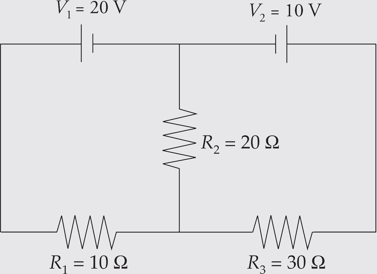
Example 5 Use Kirchhoff’s Rules to determine the current through R2 in the following circuit:
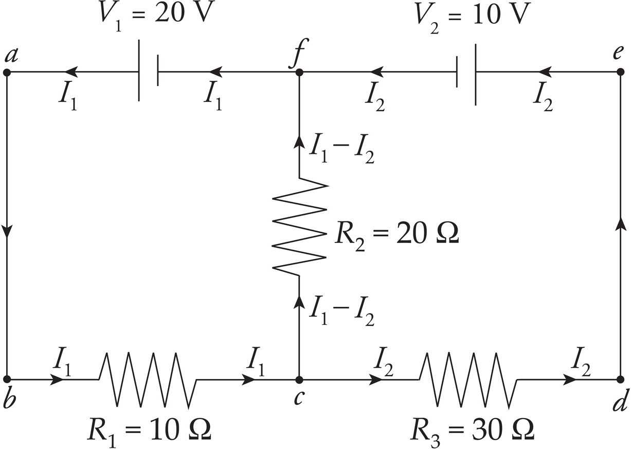
Solution. First, let’s label some points in the circuit.

The points c and f are junctions (nodes). We have two nodes and three branches: one branch is fabc, another branch is cdef, and the third branch is cf. Each branch has one current throughout. If we label the current in fabc I1 and the current in branch cdef I2 (with the directions as shown in the diagram below), then the current in branch cf must be I1 − I2, by the Junction Rule: I1 comes into c, and a total of I2 + (I1 − I2) = I1 comes out.
Now pick a loop, say, abcfa. Starting at a, we go to b, then across R1 in the direction of the current, so the potential drops by I1R1. Then we move to c, then up through R2 in the direction of the current, so the potential drops by (I1 − I2)R2. Then we reach f, turn left, and travel through V1 from the negative to the positive terminal, so the potential increases by V1. We now find ourselves back at a. By the Loop Rule, the total change in potential around this closed loop must be zero, and
−I1R1 − (I1 − I2)R2 + V1 = 0 (1)
Since we have two unknowns (I1 and I2), we need two equations, so now pick another loop; let’s choose cdefc. From c to d, we travel across the resistor in the direction of the current, so the potential drops by I2R3. From e to f, we travel through V2 from the positive to the negative terminal, so the potential drops by V2. Heading down from f to c, we travel across R2 but in the direction opposite to the current, so the potential increases by (I1 − I2)R2. At c, our loop is completed, so
−I2R3 − V2 + (I1 − I2)R2 = 0 (2)
Substituting in the given numerical values for R1, R2, R3, V1, and V2, and simplifying, these two equations become
3I1 − 2I2 = 2 (1′)
2I1 − 5I2 = 1 (2′)
Solving this pair of simultaneous equations, we get
I1 =  A = 0.73 A and I2 =
  A = 0.09 A
So the current through R2 is I1 − I2 =  A = 0.64 A.
The choice of directions of the currents at the beginning of the solution was arbitrary. Don’t worry about trying to guess the actual direction of the current in a particular branch. Just pick a direction, stick with it, and obey the Junction Rule. At the end, when you solve for the values of the branch current, a negative value will alert you that the direction of the current is actually opposite to the direction you originally chose for it in your diagram.
Answers and explanations can be found in Chapter 13.
1. For an ohmic conductor, doubling the voltage without changing the resistance will cause the current to
(A) decrease by a factor of 4
(B) decrease by a factor of 2
(C) increase by a factor of 2
(D) increase by a factor of 4
2. If a 60-watt light bulb operates at a voltage of 120 V, what is the resistance of the bulb?
(A) 2 Ω
(B) 30 Ω
(C) 240 Ω
(D) 720 Ω
3. Which of the following would be most effective at decreasing the resistance of a metal resistor?
(A) Increasing the length
(B) Increasing the cross-sectional area
(C) Using a material of greater density
(D) Using glass instead of metal

4. Determine the equivalent resistance between points a and b.
(A) 0.25 Ω
(B) 0.333 Ω
(C) 1.5 Ω
(D) 2 Ω

5. Three identical light bulbs are connected to a source of emf, as shown in the diagram above. What will happen if the middle bulb burns out?
(A) The light intensity of the other two bulbs will decrease (but they won’t go out).
(B) The light intensity of the other two bulbs will increase.
(C) The light intensity of the other two bulbs will remain the same.
(D) More current will be drawn from the source of emf.

6. What is the voltage drop across the 12 Ω resistor in the portion of the circuit shown above?
(A) 24 V
(B) 36 V
(C) 48 V
(D) 72 V

7. What is the current through the 8 Ω resistor in the circuit shown above?
(A) 0.5 A
(B) 1.0 A
(C) 1.5 A
(D) 3.0 A
8. How much energy is dissipated as heat in 20 s by a 100 Ω resistor that carries a current of 0.5 A ?
(A) 50 J
(B) 100 J
(C) 250 J
(D) 500 J
9. Three light bulbs are initially connected in series to a battery. If a fourth light bulb is then added and is also in series with the other three light bulbs, what happens to the current delivered by the battery?
(A) The current increases.
(B) The current remains the same.
(C) The current decreases.
(D) The current increases and then decreases.
1. Consider the following circuit:
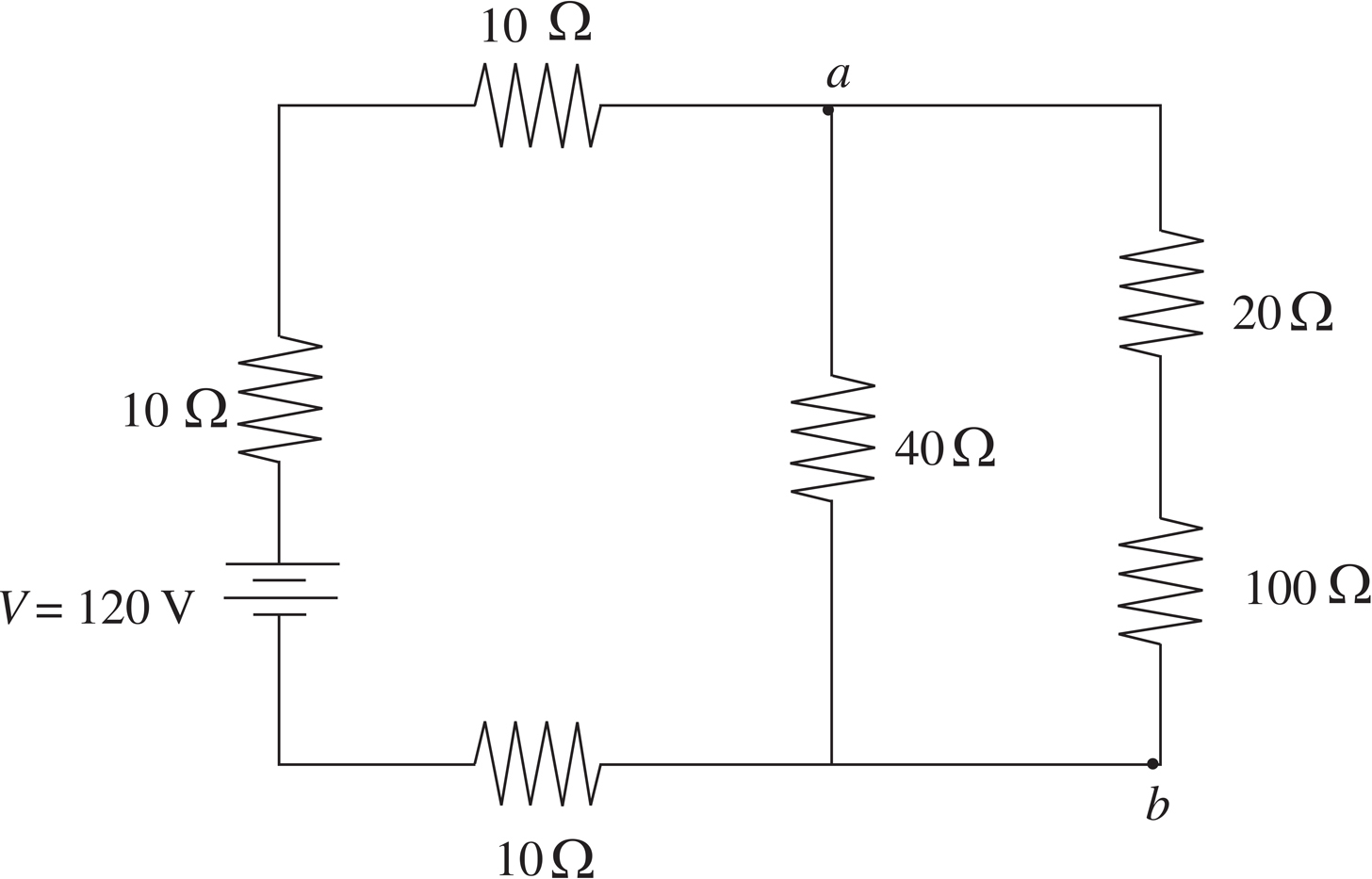
(a) At what rate does the battery deliver energy to the circuit?
(b) Find the current through the 40 Ω resistor.
(c) (i) Determine the potential difference between points a and b.
(ii) At which of these two points is the potential higher?
(d) Find the energy dissipated by the 100 Ω resistor in 10 s.
2. Consider the following circuit:

(a) What is the current through each resistor?
(b) What is the potential difference across each resistor?
(c) What is the equivalent resistance of the circuit?
The current is the rate at which charge is transferred and given by 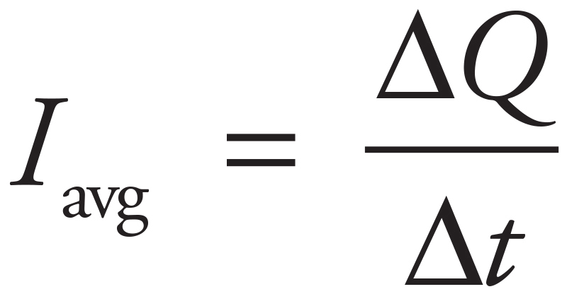 .
.
Many objects obey Ohm’s Law, which is given by V = IR.
Resistance can also be calculated by the equation R = ρL/A.
The electrical power in a circuit is given by
P = IV or P = I2R or 
This is the same power we’ve encountered in our discussion of energy 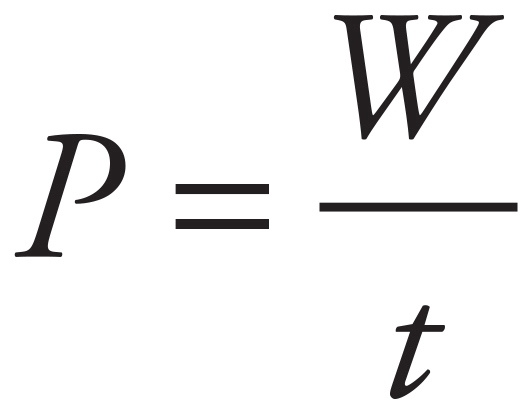 .
.
In a series circuit
VB = V1 + V2 +…
IB = I1 = I2 =…
Req = R1 + R2+…

In a parallel circuit
VB = V1 = V2 =…
IB = I1 + I2+…
1/Req = 1/R1 + 1/R2+…

Kirchhoff’s Loop Rule tells us that the sum of the potential differences in any closed loop in a circuit must be zero.
Kirchhoff’s Junction Rule (Node Rule) tells us the total current that enters a junction must equal the total current that leaves the junction.
You made it through the content review section of this book! Before moving on to Practice Test 2, review the list of terms and concepts below and make sure you can define each one. Circle any terms you don’t know, and then go back to the appropriate chapter to refresh your memory. Note: This list is not comprehensive; you should revisit each chapter and review the terms in bold to gain a deeper understanding of the concepts listed here.
Chapter 3
vector
scalar
vector addition
vector subtraction
two-dimensional vector
horizontal basis vector
vertical basis vector
unit vector
vector components
scalar components
Chapter 4
total distance vs. displacement
speed vs. velocity
average speed
uniform accelerated motion
projectile motion
acceleration
launch angle
range
Chapter 5
Newton’s First Law
Law of Inertia
Newton’s Second Law
Newton’s Third Law
mass versus weight
normal force
free-body diagram
friction
static versus kinetic (sliding) friction
coefficient of friction
pulleys
inclined planes
Chapter 6
energy
work
kinetic energy
Work-Energy Theorem
potential energy
gravitational potential energy
conservative versus nonconservative forces
total mechanical energy
Law of Conservation of Total Energy
power
Chapter 7
linear momentum
impulse
Impulse–Momentum Theorem
elastic versus inelastic versus perfectly inelastic collisions
Chapter 8
uniform circular motion
centripetal acceleration
centripetal force
Newton’s Law of Gravitation
gravitational force
universal gravitational constant
angular vs. translational displacement
angular velocity
Right-Hand Rule
angular acceleration
center of mass
torque
translational equilibrium, rotational equilibrium, static equilibrium
rotational inertia
angular momentum
Chapter 9
simple harmonic motion
spring constant
amplitude
elastic potential energy
period
frequency
hertz
effective spring constant
simple pendulum
Chapter 10
amplitude
propagates
transverse
frequency
superposition/interference
constructive interference
destructive interference
in phase versus out of phase
standing wave
node
antinode
harmonic/resonant wavelength
harmonic number
harmonic/resonant frequency
fundamental standing wave
compression
rarefaction
longitudinal wave
bulk modulus
beat
beat frequency
Doppler effect
Chapter 11
nucleons
electromagnetic force
electric charge
charged
ionization
conserved
elementary charge
quantized (is mispelled currently)
coulombs
Coulomb’s Law
electric force
Coulomb’s constant
permittivity of free space
superposition
electric field
gravitational field
electric field vector
electric dipole
Chapter 12
drift speed
average current
ampere
resistance
ohm
voltage
current
circuit
direct current
electromotive force (emf)
resistor
positive/negative terminal
series versus parallel
grounded
Junction Rule
Node Rule
Loop Rule