Chapter 11
Landing Performance
Landing performance involves decelerated motion. During the landing phase of flight, the aircraft touches down at a certain velocity, then decelerates to zero velocity. This chapter discusses the approach to a landing and factors in reducing speed once the aircraft has touched down. The following considerations are very important factors in evaluating landing performance for a given aircraft, location, mission, and pilot technique:
- Approach paths/speeds, including obstacle clearance
- Deceleration during landing
- The distance required to stop the aircraft
- Regulatory guidance and/or company operation specifications
- Hazards of hydroplaning
- Go‐around/missed approach
As with takeoff performance, there are many factors that affect the calculation of landing performance:
- Aircraft gross weight
- Thrust on the aircraft
- Temperature
- Pressure altitude
- Wind direction and velocity
- Runway slope
- Runway surface
The manufacturer of the aircraft publishes operating specifications, as well as performance charts and tables for the pilot to follow. As the seven factors above change, because one or more of them will on every flight, the pilot must adjust accordingly to remain inside the operating envelope of the aircraft (Fig. 11.1). As we discussed in the previous chapter, this is a complex subject and the simplified discussion presented here should not be used to supersede the information presented in the pilot's handbook.
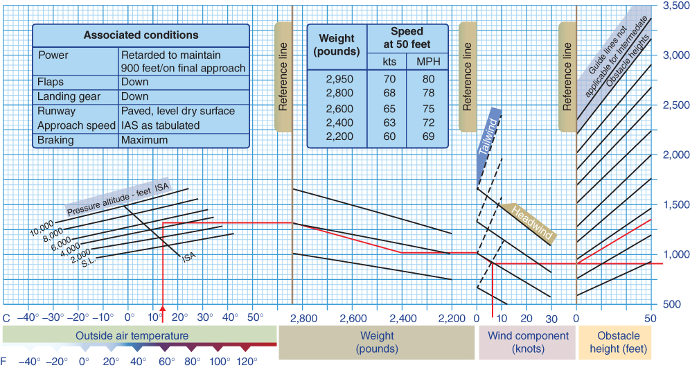
Figure 11.1 Landing distance graph.
U.S. Department of Transportation Federal Aviation Administration, Pilot's Handbook of Aeronautical Knowledge, 2008
PRELANDING PERFORMANCE
Gliding Flight
One of the most important concepts of aerodynamics is equilibrium of forces, which was discussed in Chapter 1. An airplane that is flying at a constant speed is in equilibrium, as shown in Fig. 11.2. If the engine(s) should fail, the thrust force is reduced to zero, and an unbalance of forces results. This means that the aircraft will not be able to maintain altitude and will start to descend. If this occurs the pilot would want to know several things:
- How far can the airplane glide?
- How long will the airplane remain airborne?
- What will the sink rate be?
- Can the plane glide to a suitable landing site?
- Can a successful engine‐out landing be made?
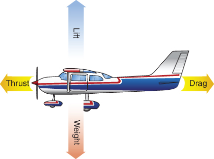
Figure 11.2 Forces in equilibrium.
U.S. Department of Transportation Federal Aviation Administration, Pilot's Handbook of Aeronautical Knowledge, 2008
An understanding of the basic aerodynamics of gliding flight should help the pilot make an intelligent estimate of the performance of the airplane in the above situation. Once the engine quits and the aircraft starts to descend, the forces acting on it are as shown in Fig. 11.3. The figure shows that the forces of lift and drag act along the vertical and longitudinal axes of the aircraft, but the weight acts toward the center of the earth. To better analyze the reaction of these forces, it is desirable to replace the weight force by two component forces that act in the same rectangular coordinate system as the lift and drag forces.
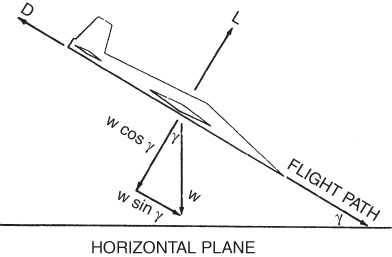
Figure 11.3 Forces acting in a power‐off glide.
The glide path makes a glide angle with the horizontal, which we will call γ (gamma). The component of the weight that acts in the direction of the aircraft's vertical axis is equal to W cos γ. It acts at the aircraft's center of gravity (CG), and opposes the lift, L. The component of weight that acts along the longitudinal axis is equal to W sin γ and opposes the drag D. In Fig. 11.3 the component W sin γ is shown at some distance below the CG. This component actually acts at the CG and is shown in the figure merely to explain the right triangle relationship of the vectors.
Once glide has been established and velocity is constant, equilibrium again exists and the force equations are


The pilot is concerned about how to achieve maximum glide ratio. Flying at maximum glide ratio means that maximum glide range will be attained. The ratio of horizontal distance to the vertical distance (altitude) is the glide ratio. To cover the most distance over the ground, the pilot wants to have the maximum glide ratio. The flight path angle must be a minimum to achieve this.
Dividing Eq. 11.1 by Eq. 11.2 gives
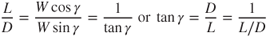
Equation 11.3 shows that the minimum glide angle is obtained at (L/D)max and, therefore, the airplane must be flown at the airspeed corresponding to the (L/D)max AOA. The glide ratio vector diagram is shown in Fig. 11.4. The tangent of the glide angle in Fig. 11.4 is equal to the opposite side divided by the adjacent side of the right angle shown in the figure. From Eq. 11.3, the tangent of the glide angle is D/L, so the opposite side of the triangle can be labeled as drag and the adjacent side can be labeled as lift. The vertical  and the horizontal
  also represent the opposite side and adjacent side of the triangle, respectively; thus, the numerical value of the L/D ratio is equal to the glide ratio.
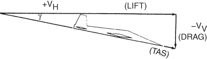
Figure 11.4 Glide ratio vector diagram.
A pilot who tries to stretch the glide by flattening the glide angle will actually decrease the glide distance. Maximum glide distance is achieved only at a minimum glide angle, and this occurs when the plane flies at (L/D)max.
The Landing Approach
Many of the performance “V‐Speeds” discussed in Chapter 10 apply to the landing approach and deceleration after landing so they will not be discussed again here. The definitions below are not a complete listing of all the speeds that may be encountered, but include the more common terms used by both transport and nontransport category aircraft.
- Approach Climb. The speed that gives the best climb performance in the approach configuration, with one engine inoperative, and maximum takeoff power on the operating engine(s), used for missed approach calculations to meet a minimum climb gradient.
- Landing Climb. The speed giving the best performance in the full landing configuration (gear down) with maximum takeoff power on all engines, used for missed approach calculations to meet a minimum climb gradient.
- Power‐off Stalling Speed ‐ VS1 (specified configuration). The speed at which the aircraft is controllable in a specified configuration, published by the manufacturer.
- Reference Speed ‐ VREF. 1.3 times the stalling speed in the landing configuration, often the required speed at the 50 ft height above the threshold on the approach end of the runway (Fig. 11.5). Do not confuse with VREF (Refusal Speed), sometimes used for takeoff.
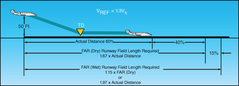
Figure 11.5 FAR landing field length required.
U.S. Department of Transportation Federal Aviation Administration, Airplane Flying Handbook, 2004
Precision flying is required to ensure a stabilized steady flight path to touchdown. The approach speed specified for the weight of the aircraft is given in the pilot's handbook and provides a margin of safety above the minimum safe airspeed for the aircraft. The minimum airspeed may depend on the aircraft's stall speed, minimum control speed, or the speed at which 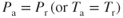 .
.
A fairly long approach path allows the pilot to stabilize the variable quantities such as airspeed, glide slope, and drift. Once these are brought under control, a smooth flight path can be maintained and a minimum of control forces will be needed to make the actual landing. Steep turns should be avoided during the alignment of the aircraft with the runway. Steep turns increase the induced drag, increase the stall speed, and will bleed off the airspeed, possibly leading to a cross controlled stall. Once proper alignment to the runway has been established, only minor banking for drift corrections will be required. The major preoccupation now becomes the approach glide path.
Various approach glide paths are shown in Fig. 11.6. Approach path A shows a steep, low‐power approach. Such an approach usually results from making the turn from the downwind leg too soon and not allowing for a long enough final approach aligned with the runway centerline. The pilot finds the plane too close to the touchdown point and at too high an altitude. There are three ways to correct this:
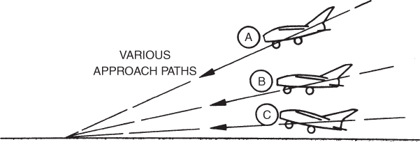
Figure 11.6 Approach glide paths.
- Cut the throttle and attempt to lose altitude rapidly. If the approach is made at idle throttle, the pilot must dive (or sideslip) the airplane to lose altitude.
- Continue the normal approach and thus land long on the runway.
- Execute a go‐around and make a new approach.
The first way results in a high rate of descent and or an increase in airspeed. Pilots of light aircraft may not have difficulty in reducing the high rate of descent by either flaring the airplane or adding throttle. In either case the plane will probably make a hard landing or float for a distance. The high rate of descent is much more serious for heavier airplanes. Recovery involves more than merely pulling the nose up to flare the plane. Such a recovery technique will add greatly to the induced drag, but will provide little increase in lift. A large increase in thrust is required to overcome the high rate of descent. In some cases there is simply not enough thrust available and a hard, short landing results.
Landing long may succeed if the runway is long enough. However, the third way—making a go‐around—is recommended. Although it may be hard on pilot ego, it is easy on the airplane. If the approach is not properly lined up on final approach, it is certainly better to perform a go‐around rather than to “press on” and hope to salvage a good landing from a poor approach. A poor approach usually leads to a poor landing.
Approach path C in Fig. 11.6 shows a long, shallow approach. This is a result of getting too low during the approach and then having to “drag it in” using high thrust and high AOA. Such approaches may be successful in propeller aircraft, but they should be avoided in all airplanes, especially turbojets. Propeller aircraft derive much more lift at high power settings due to the air being blown over the wing area behind the propellers, as shown in Fig. 11.7a.
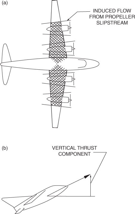
Figure 11.7 Lift from (a) propellers and (b) turbojets.
The only advantage of making a high‐thrust approach in a conventional jet aircraft is the generation of lift from the vertical component of thrust, as shown in Fig. 11.7b. The large increase in drag that results from the high AOA for the jet aircraft far exceeds the benefits of the lift.
Propeller aircraft are power producers; this means that they produce high thrust at low airspeeds. Propeller aircraft do not suffer from a thrust deficiency at low airspeeds as do jet aircraft. Even with the advantages of blowing air and high thrust available, propeller aircraft should not be flown in a low, flat, high‐powered approach. Engine failure under this type of approach can be disastrous. Thus, the intermediate approach B is desirable. It does not require a high rate of sink, excessive speed, or the extreme flare that the steep approach requires. The intermediate path also does not require the high thrust and AOA that the low path does. Figure 11.8 shows the effects of flaps on the approach angle and landing point for a single‐engine propeller aircraft.
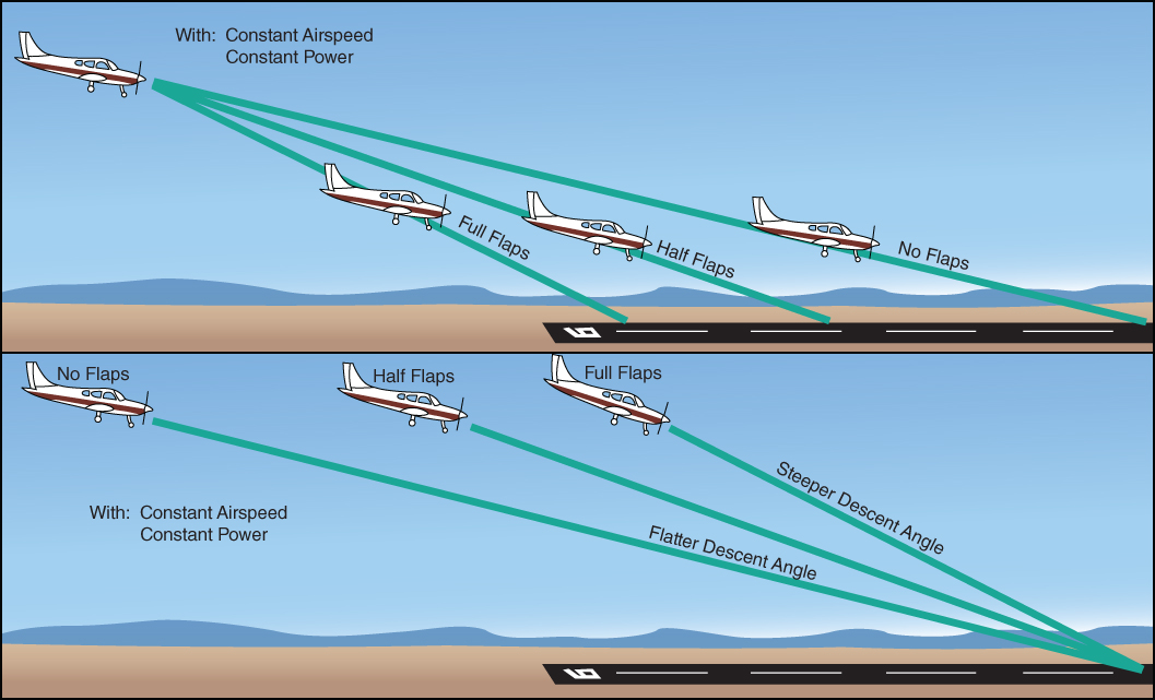
Figure 11.8 Effect of flaps on final approach.
U.S. Department of Transportation Federal Aviation Administration, Airplane Flying Handbook, 2004
A stabilized aircraft, with proper airspeed control management on final approach, has the best chance of avoiding common pitfalls during the landing phase of the flight. These pitfalls include late or rapid roundout in the flare, floating, ballooning, porpoising, or bouncing the aircraft. All of these items lead to longer landing distance, and in extreme conditions damage to the aircraft. Once established on the proper approach path and aircraft heading, the pilot must control the airspeed and altitude. The proper AOA will produce the desired airspeed. Lowering the AOA will increase the airspeed, and increasing the AOA will lower the airspeed. As we have emphasized several times, the stick controls the airspeed. Once proper airspeed has been established, the primary control of the rate of descent will be the throttle.
IMPROPER LANDING PERFORMANCE
The final descent and landing of any aircraft should be stabilized, on airspeed, and allow a landing within the touchdown zone. We previously discussed the hazards of not preparing accordingly for ground effect, and the consequences of approaching a runway in a steep descent with idle thrust, or when low and slow with high thrust settings. Unstablized approaches commonly lead to unstabilized landings outside the briefed touchdown area, off airspeed, or with improper technique by the pilot to try and correct for a deteriorating situation. In almost all cases the pilot should execute a go‐around or missed approach. Better to attempt another approach then force an unstabilized approach and landing.
Improper Roundout
To most passengers, an approach and smooth landing seem like a normal and nonintensive act by the pilot in concert with the aircraft. In fact, a smooth and stable approach and landing occurs only because a pilot generates the proper technique and feel for the aircraft over hundreds, if not thousands, of landings. Understanding energy management, and when to begin the roundout and flare is imperative to a successful landing, and achieving the performance for stopping distance calculated before landing. A high roundout commonly leads to the slowing of the aircraft well above the runway, and well into the region of reversed command, and within seconds the airspeed begins to slow and approaches stall speed. The critical angle of attack is near as the AOA increases when the pilot maintains back pressure on the stick. Depending on the severity of the pitch, and the indicated airspeed, power should be added while level pitch is maintained until the aircraft is able to reestablish the proper landing attitude (Fig. 11.9). In most cases a go‐around should be initiated.
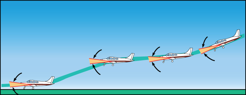
Figure 11.9 High roundout.
U.S. Department of Transportation Federal Aviation Administration, Airplane Flying Handbook, 2004
Delaying roundout can be just as detrimental as rounding out too high. If the pilot suddenly decides that impact is imminent, pulling back too aggressively on the stick can lead to an accelerated stall due to high stall speed and critical AOA, complicating an already unstable situation. If the pilot is unable to raise the nose in time, then the nosewheel of the aircraft may strike the runway. This may damage the nose landing gear and may result in the aircraft bouncing back into ground effect. In either case it is advisable to pitch for airspeed, initiate a go‐around, and retract flaps and gear as applicable once positive climb rate has been established.
Floating during roundout is a common occurrence for student pilots, or when pilots are transitioning to new aircraft and are unsure of proper approach airspeed. Sometimes excessive floating is blamed on ground effect, when in reality it is a combination of ground effect and poor approach technique by the pilot. If too much thrust is carried into the landing flare, or the pilot dives to the runway to achieve a prescribed landing point, extra airspeed will be carried into the landing flare. If the runway is short there may be insufficient landing distance to stop the aircraft once touchdown has been made, or the pilot may attempt to force the aircraft on the runway further complicating the situation. If sufficient runway is remaining, the pilot should decrease power, maintain level pitch attitude, and let the airspeed bleed off in the flare. As the airspeed decreases, greater AOA will be required to maintain level flight over the runway, eventually touching down on the main landing gear allowing aerodynamic braking to slow the aircraft.
Bouncing and Ballooning
In the previous section we discussed improper roundout and how both the pilot and aircraft commonly react to leveling too high or leveling too low when initiating the landing flare. This section focuses on the aircraft's reaction, and proper pilot technique, should the improper roundout be allowed to progress further into a negative situation resulting in excessive AOA.
When a pilot feels that the descent rate is too excessive, they may pull back on the stick resulting in a taildown force, raising the nose as well as the AOA, thus increasing the lift. The sudden increase in lift results in the aircraft ballooning away from the runway and possibly above ground effect. As we discussed with the dangers of overrotation, the airspeed will now be decreasing, the wing will be closer to the critical  , and the aircraft will be in a nose high attitude. Depending on the type of aircraft and power setting, left turning tendencies may be enhanced possibly resulting in the longitudinal axis being diverted left of centerline, and should any crosswind exist the aircraft is subject to drifting left or right of the intended path. If the aircraft does balloon out of ground effect, the nose may pitch up further due to the effects discussed previously as a taildown pitching moment develops, as will induced drag. Experience will dictate what corrective action is best for each situation, but usually the best corrective action is to maintain a proper angle of attack to minimize airspeed loss and initiate a go‐around. If the balloon is managed properly, runway is available, and the aircraft is a safe distance above the runway, the pilot should reinstate a proper AOA, and add power as needed to cushion the landing, use proper rudder to maintain the longitudinal axis down the centerline, and touchdown on the main gear.
Bouncing during touchdown results from similar pilot technique as ballooning, with the exception of the pilot letting the aircraft touch down and bounce at least once into the air, if not multiple times. Due to a pilot's common reaction of pulling back on the stick, and the reactive movement of the tail in a downward direction as the main gear strikes the runway, the nose goes up and the AOA is increased. Again CL is increased and approaching CL(max) depending on the momentum of the aircraft when striking the runway, and respective pilot reaction to recover. If the aircraft exits ground effect, a nose‐high pitching moment may be realized, induced drag is increased, and the same deteriorating situation as ballooning may occur. Corrective action should be the same; in most cases initiate a go‐around maintaining the proper AOA for climb and “clean‐up” the aircraft as applicable when a positive rate of climb has been established. If a bounce is not severe, a proper landing attitude can be established, and a normal touchdown can be made as long as rudder is used to align the longitudinal axis with the centerline and correction for any drift has been made for the crosswind.
Porpoising
Excessive floating during the roundout and flare always leads to excessive runway usage. As usual when excessive floating may result in an unsafe touchdown, or a touchdown with limited runway remaining, a go‐around is recommended. Unfortunately, many pilots during training, or when transitioning to a new aircraft, attempt to force the airplane onto the runway when enough lift still is being developed for the aircraft to fly. As a result the aircraft begins to porpoise similar to the way a true porpoise moves in and out of the water. These oscillations by the pilot can become worse during the flare if the pilot jockeys the throttle, or overcorrects as the AOA of the wing is varied by the constantly moving elevator and loss of taildown force in ground effect. Sometimes during these oscillations the nosewheel is allowed to strike the runway forcing the aircraft back in the air and in a nose‐high, increasing AOA situation. If a go‐around is not selected, a proper landing AOA should be initiated, power as required to cushion the landing, and proper use of aerodynamic braking on the runway without the aircraft climbing back into ground effect (Fig. 11.10).
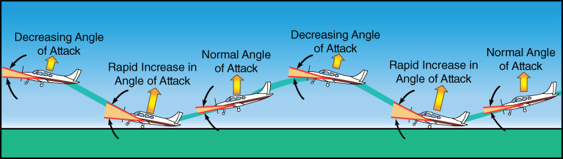
Figure 11.10 Porpoising during roundout.
U.S. Department of Transportation Federal Aviation Administration, Airplane Flying Handbook, 2004
If a pilot lands when the aircraft is still producing enough lift on the wing for the aircraft to fly and then adds forward stick, a situation known as wheelbarrowing may occur. Due to the deflection of the elevator or stabilator with a forward stick, the lift on the tail is now an upward force and more pressure is placed on the nosewheel. This situation can also occur when a pilot is on takeoff roll and continues to force the aircraft on the runway when the wing is producing sufficient lift to fly. Proper corrective technique is to reestablish aft pressure on the stick, and for a landing verify that the throttle is set in the idle position. Depending on aircraft manufacturer recommendations, as well as the operating rules or the pilot, flaps can be retracted, placing more weight on wheels and lowering the CL of the wing.
Improper Crosswind Landing
Most of the time when landing on a runway the wind will not be aligned with the runway as a headwind without some crosswind component. Crosswind landings are usually a challenging obstacle to new pilots, and therefore limits are set by instructors, flight schools, employer operating specifications, or the manufacturer. Improper crosswind landing (and takeoff) technique can lead to unwanted side loads on landing gear, structural damage to the aircraft including wingtips, and at the very least increased lack of confidence by the pilot. Proper understanding of crosswind limitations, pilot technique, and the aerodynamic forces at play greatly influence the positive outcome of a crosswind landing.
When a pilot transitions from the landing approach into the flare, the aircraft's longitudinal axis should be aligned parallel to the runway centerline, and the aircraft should be over the center of the runway without drift in either direction. Figure 11.11 shows the wind is from the pilot's left and improper crosswind correction is currently being used. The aircraft is drifting to the pilot's right as the wind is pushing on the left side of the aircraft and underneath the wing. The inertia force is to the right, so all the weight of the movement of the aircraft rests on the right main gear at touchdown. This action results in the left wingtip rising even more due to the moment created, and possibly the right wingtip striking the ground in a low‐wing aircraft, or in extreme cases a ground loop (especially with conventional gear aircraft).
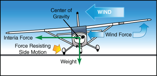
Figure 11.11 Improper drift correction.
U.S. Department of Transportation Federal Aviation Administration, Airplane Flying Handbook, 2004
In addition to the negative side effects discussed above, quite often the aircraft will weathervane into the wind, resulting in the longitudinal axis of the airplane becoming misaligned with the runway centerline. As the aircraft touches down on the downwind main landing gear, the aircraft may pivot more into the wind complicating the landing or eventual go‐around.
After using a crabbing approach with the aircraft weathervaning into the wind so the aircraft's groundtrack remains aligned with the centerline of the runway, a common technique to counteract the forces due to crosswind component is to transition to sideslip correction when in the flare (Fig. 11.12). In this case the longitudinal axis is aligned with the centerline by proper application of the rudder, and to lower the upwind wing into the wind to initiate a sideslip equal to the force of the wind so no drifting left or right of centerline occurs. The aircraft should touch down on the upwind main gear first, then downwind main gear, then finally the nosewheel. As the aircraft slows down in the flare and after landing, aerodynamic forces on the ailerons and rudder are lowering and they are becoming less effective. Thus, more control input is required from the pilot to maintain centerline and prevent drift as the crosswind velocity has remained unchanged. During rollout full aileron may be needed to keep the upwind wing on the ground while less rudder will be required once the nosewheel is on the ground. Manufacturers publish the maximum demonstrated crosswind component in the aircraft's flight manual; this should be treated as a number never to exceed, requiring selection of an alternate runway or airport should the crosswind component exceed this value. A discussion on sideslips and forward slips is found later in this textbook.
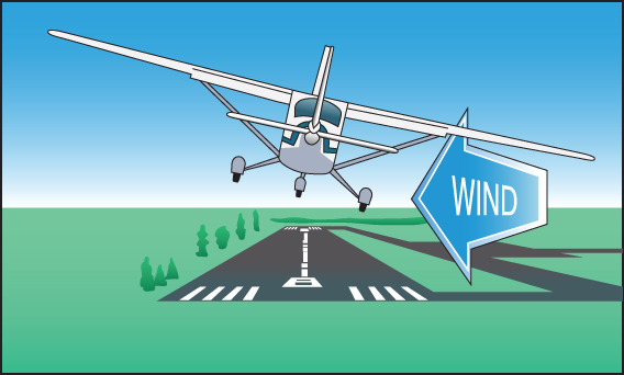
Figure 11.12 Sideslip during crosswind.
U.S. Department of Transportation Federal Aviation Administration, Airplane Flying Handbook, 2004
LANDING DECELERATION, VELOCITY, AND DISTANCE
Forces on the Aircraft during Landing
Transport and other large aircraft use a different landing technique than fighter and attack aircraft. Nearly all modern transports have nonskid brakes, ground spoilers, and thrust reversers. They land in a three‐point attitude and deploy spoilers, thrust reversers, and brakes soon after touchdown. The landing forces on these aircraft are shown in Fig. 11.13. Thrust reverser forces are not shown in the figure.
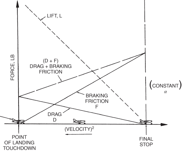
Figure 11.13 Forces acting on an airplane during landing.
Fighter, attack, and similar high‐performance aircraft use aerodynamic drag braking as well as brake friction to slow the airplane. The use of aerodynamic drag is most efficient to assist deceleration when at least 60–70% of the touchdown speed. These forces are shown in Fig. 11.14. It is assumed that:
- The aircraft has a tricycle landing gear and lands on the main gear and the pilot holds the nose up to take advantage of the aerodynamic drag.
- Foot brakes are not applied until the pilot can no longer keep the nose wheel off the runway.
- The aircraft does not develop lift in the three‐point position and the nose wheel is on the runway.
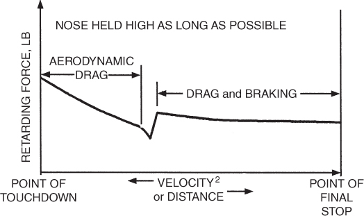
Figure 11.14 Aerodynamic braking and wheel braking.
Braking action of the wheel brakes involves many factors, including:
- Tire material
- Tread design and condition
- Runway surface material and condition
- Amount of braking applied (wheel slippage)
- Amount of normal (squeezing) force between tires and the runway
- Pilot technique
Friction is defined as a force that develops between two surfaces that are in contact with each other when an attempt is made to move them relative to each other. The friction force, F, is related to the force that is pressing the surfaces together, called the normal force, N, by a dimensionless factor called the coefficient of friction, μ (mu):

Figure 11.15 illustrates these forces.
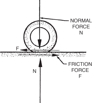
Figure 11.15 Normal and friction forces.
The coefficient of friction for a certain tire material, tread design, and tire wear operating on a dry concrete runway is a function of the amount of brakes being applied. This braking is defined as a percentage of slip between the tire and the runway. Zero percent slip is a rolling tire with no braking action. A locked wheel that skids without turning is defined as 100% slip.
A plot of the coefficient of friction versus wheel slippage is shown in Fig. 11.16. The maximum braking coefficient of friction can be seen to be about 0.7. It occurs when wheel slip is about 10%. Locking the wheels reduces the value to about 0.5, causes the tires to wear unevenly, and may cause tire blowout. Water, snow, or ice on the runway causes a large reduction of the coefficient of friction, as shown in Fig. 11.17.
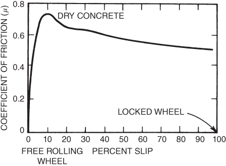
Figure 11.16 Coefficient of friction versus wheel slippage.
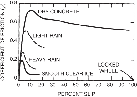
Figure 11.17 Effect of runway condition on coefficient of friction.
Braking Techniques
The technique of using braking devices may vary in detail with aircraft type and model, but general principles can be stated for aircraft using aerodynamic braking. During the initial landing roll the velocity and dynamic pressure is high and aerodynamic braking will be most effective, especially when above 60% of the touchdown speed. Holding the nose of a tricycle landing gear airplane high will increase the parasite drag and is an effective method of slowing the aircraft. Use of speed brakes and full down flaps has the same effect.
At some point during the landing roll the reduced airspeed will cause the elevator to lose effectiveness, and the nose of the aircraft can no longer be held off the runway. Usually this is the point where wheel braking is initiated and becomes the principal method of stopping the aircraft (in combination with thrust reversers if applicable). There is often a debate over whether it is better to retract the flaps, thus increasing the weight on the wheels, or to leave them down, thus preserving the aerodynamic braking effect. Inadvertent retraction of the landing gear instead of the flaps has occurred; best practice is to leave the flaps down until taxiing off the runway, unless as required by the manufacturer to obtain maximum short‐field performance.
Wheel braking force for all aircraft will be a maximum when the normal force on the braked wheels is greatest. For a tricycle landing gear aircraft, this will occur when the control stick is held in the back position. Many pilots have a tendency to release back pressure when the nose wheel contacts the runway. This should be avoided and the stick should be held full back as long as braking action is desired.
LANDING EQUATIONS
General Equation
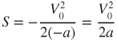
The calculation of landing distance, S, in terms of touchdown velocity, V0, and deceleration, −a, is similar to the takeoff case, which was shown in Eq. 10.4 to be
To determine how the landing distances are affected by variations in weight, altitude, and wind conditions, a ratio is established similar to that used for the takeoff case (Eq. 10.6):
Effect of Weight Change
Changing the gross weight of a landing aircraft affects the landing speed in the same way the takeoff speed was affected. For an increase in gross weight, a greater speed will be required due to the increase in lift needed for the increase in weight. The landing speed must be changed by using Eq. 4.3:
Changing the weight of the aircraft has no effect on the deceleration of the aircraft, caused by the braking action. At first, this statement sounds strange, but the heavier the aircraft, the more the weight on the braking wheels. So, more braking force is available to counteract the greater weight to be decelerated. For the braked phase of the landing,

Substituting these last two equations into Eq. 10.6 gives the effect of a weight change on landing distance. An increase in gross weight translates to an increase in landing distance:

Effect of Altitude
Aircraft airspeeds are affected by the same factors at altitude whether the aircraft is taking off or landing, as pressure and temperature change, so does the density of the air and the performance of the aircraft. An increase in density altitude increases the landing speed, IAS will remain the same but TAS increases. In mountain flying operations, this higher than normal TAS can lead to problems on landing, as the ground speed (GS) will be higher. This apparent higher GS may cause the pilot to inadvertently slow the IAS to near stall speed as he or she tries to make the approach speed closure rate look “normal.” Fly by the numbers to remain safe.
The equation showing the velocity change at altitude holds for the landing phase as well:

Unless the aircraft is equipped with thrust reversers, it does not rely on the engine performance to decelerate the aircraft as it did for takeoff acceleration. So,

Substituting the values from these last two equations into Eq. 10.6 gives us the effect of altitude on landing distance for all non‐thrust‐reverser aircraft:

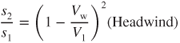
Effect of Wind
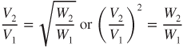
A headwind will decrease the landing distance and a tailwind will increase the landing distance due to the change in touchdown velocity. Figure 11.18 shows us once again the effect on landing with a headwind or tailwind. Figure 11.19 reflects the effect of a headwind on flightpath when compared to a no‐wind situation, so precautions must be made if attempting to glide into a headwind if experiencing an engine loss in a single‐engine aircraft.
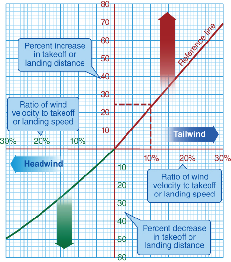
Figure 11.18 Effect of wind on landing.
U.S. Department of Transportation Federal Aviation Administration, Pilot's Handbook of Aeronautical Knowledge, 2008
Figure 11.19 Effect of headwind during landing approach.
U.S. Department of Transportation Federal Aviation Administration, Airplane Flying Handbook, 2004
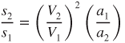
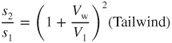
Headwinds and tailwinds affect takeoff and landing performance in exactly the same way, so Eqs. 10.10 and 10.11 apply to the landing situation also. We rewrite them with new equation numbers:
Runway Surface and Slope
We discussed in Chapter 10 that most performance charts are for a paved, smooth, level, and dry runway surface. When calculating landing distance many of the same concerns become factors that must be incorporated into the manufacturer's performance charts. Not only will contamination on the runway impact friction and deceleration, but braking action may be impacted as well and required runway length for stopping increased. Poor approach procedures, combined with higher VREF speeds in icing conditions, and finally contamination on the runway can lead to a large increases in runway length required.
As with takeoff performance, the slope or gradient of the runway can greatly impact stopping distance. Landing uphill reduces landing rollout while landing downhill will increase landing rollout. Due to possible visual illusions for upsloping and downsloping runways, improper approach flightpaths can lead to increased landing speeds. Always consider the warnings, notes, and conditions published on the performance charts or in your personal limitations.
HAZARDS OF HYDROPLANING
Hydroplaning occurs when a tire loses contact with the runway surface due to a buildup of water or slush in the tire ground contact area. Besides the obvious dangers you may already associate with hydroplaning, other adverse effects may occur such as ground controllability and weathervaning into a strong crosswind. NASA has researched this problem and identified three forms of hydroplaning: dynamic, viscous, and reverted rubber.
Dynamic Hydroplaning
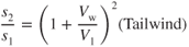
Dynamic hydroplaning is caused by the buildup of hydrodynamic pressure at the tire pavement contact area and usually occurs at relatively high speeds. The pressure creates an upward force that effectively lifts the tire off the surface. When complete separation of the tire and pavement occurs, the condition is called total dynamic hydroplaning, and wheel rotation will stop.
Figure 11.20 shows the forces on a tire without the presence of water on the runway. Figure 11.20a shows a standing tire with the only forces being the weight of the aircraft and the ground reaction opposing it. As the aircraft moves to the left, as shown in Fig. 11.20b, the ground friction causes a spin‐up moment and wheel rotation results. When the tire is rolling freely at a fixed speed on a dry runway, the vertical ground reaction shifts forward of the axle and a spin‐down moment that offers resistance to the wheel rotation is developed. When these two moments are equal, the wheel is turning at a constant rpm.
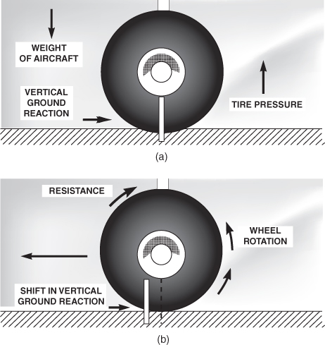
Figure 11.20 Forces on tire: (a) static condition, (b) rolling tire.
The introduction of water on the runway leads to dynamic hydroplaning, which is shown in Fig. 11.21. Deep fluid on the runway creates additional drag on the tire when it is displaced from the tire path, and a high‐spray pattern is produced, as shown in Fig. 11.21a. As the forward speed of the aircraft is increased (Fig. 11.21b), the spray pattern thrown up by the tire lowers and the wedge of water penetrates the tire–ground contact area and produces a hydrodynamic lift force on the tire. This is partial hydroplaning. As the speed increases the spray pattern becomes flatter, and the wedge of fluid penetrates farther into the ground contact area until at some high forward speed complete separation of the tire and runway takes place and total hydroplaning occurs, as shown in Fig. 11.21c.
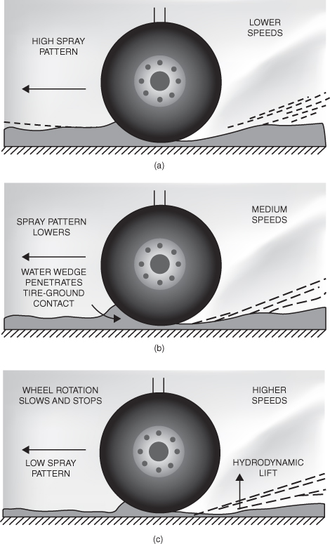
Figure 11.21 Hydroplaning forces on tire: (a) low speed, (b) medium speed, (c) high speed.
The ground friction is progressively reduced as the wedge of water penetrates beneath the tire. It approaches zero at total hydroplaning, and the spin‐down moment causes the tire to stop the wheel rotation. Obviously no braking action is available when the wheel is not making contact with the runway and has stopped rotating.
Total dynamic hydroplaning is more of a landing than a takeoff problem, but crosswind takeoffs are dangerous under these conditions. The approximate speed at which total dynamic hydroplaning occurs is

Where
| VH | = | hydroplaning speed (knots) |
| P | = | tire inflation pressure (psi) |
Total dynamic hydroplaning usually does not occur unless a severe rain shower is in progress. There must be a minimum water depth present on the runway to support the tire. The exact depth cannot be predicted since other factors, such as runway smoothness and tire tread, influence dynamic hydroplaning. Both smooth runway surface and smooth tread tires will induce hydroplaning with lower water depths. While the exact depth of water required for hydroplaning has not been accurately determined, a conservative estimate for an “average” runway is that water depths in excess of 0.1 in. may induce full hydroplaning.
Viscous Hydroplaning
Viscous hydroplaning is more common than dynamic hydroplaning. Viscous hydroplaning may occur at lower speeds and at lower water depths than dynamic hydroplaning. Viscous hydroplaning occurs when the pavement surface is lubricated by a thin film of water. The tire is unable to penetrate this film, and contact with the pavement is partially lost. Viscous hydroplaning often occurs on smooth runway pavements or where rubber deposits are present, usually in the touchdown area where a thin water film can significantly reduce the coefficient of friction.
Reverted Rubber Hydroplaning
The third type of hydroplaning is known as reverted rubber (steam) hydroplaning. Often this type of hydroplaning is the result of the pilot's poor technique initially at higher speeds when the aircraft begins dynamic hydroplaning, then becomes reverted rubber hydroplaning at lower speeds when the wheels are still locked and eventually make contact with the runway. White streaks on the runway are an indication that this type of hydroplaning has occurred. Examination of the aircraft tire will show an elliptically shaped tacky or melted rubber condition. This condition occurs when the heat that is generated during a locked wheel skid reverts the rubber to a softer slippery state.
Methods to prevent hydroplaning include transverse runway grooving, frequent removal of rubber deposits from the touchdown areas, maximum use of aerodynamic braking, and pilot education.
SYMBOLS
| N | Normal force (lb) |
| P | Tire inflation pressure (psi) |
| VH | Hydroplaning speed (knots) |
| VS1 | Power‐off stalling speed (specified configuration) (knots) |
 |
Reference speed (knots) |
| γ (gamma) | Glide angle (degrees) |
| μ (mu) | Coefficient of friction |
EQUATIONS
- 11.1

- 11.2

- 11.3

- 11.4

- 11.5

- 11.6

- 11.7
- 11.8

PROBLEMS
- An airplane is in trimmed flight and its velocity is constant.
- It has no unbalanced forces acting on it.
- It has no unbalanced moments acting on it.
- It is in a state of equilibrium.
- All of the above are true.
- An airplane is in a constant velocity engine out glide. Its altitude is decreasing. It is not in a state of equilibrium.
- True
- False
- At (L/D)max an airplane will
- be at minimum glide angle.
- be achieving maximum glide distance.
- have a glide ratio equal to the numerical value of
 .
. - All of the above
- A steep, low‐power approach is more dangerous for heavy airplanes than light airplanes because
- recovery from a high rate of descent involves a great increase in power (or thrust).
- the aircraft will float down the runway and possibly overshoot the runway.
- flaring the aircraft to decrease the rate of descent increases induced drag.
- Both (a) and (c)
- A low‐angle, high‐power (or thrust) approach
- may be used for propeller aircraft if a short field landing is required.
- is dangerous for propeller aircraft if an engine fails.
- should be avoided at any cost for jet airplanes as high induced drag results.
- All of the above
- Aerodynamic drag is more effective than wheel braking during the first part of a landing.
- True
- False
- As a general rule, when the nose of a tricycle landing gear airplane can no longer be held off the runway, it is time to start applying wheel brakes.
- True
- False
- In applying wheel brakes, it is not a good idea to apply full brake pressure because:
- you might cause a blowout.
- you get lower coefficients of friction when wheel slippage exceeds about 15%.
- Both (a) and (b)
- In general, if maximum wheel braking of a tricycle landing gear airplane is desired, the pilot should keep the stick full back even after the nose is on the runway.
- True
- False
- Headwinds and tailwinds affect the landing distance by the same amount as they affect the takeoff distance.
- True
- False


- Sea level standard conditions
- Calculate the deceleration.
- Calculate the no‐wind stopping distance.
- If the weight is increased to 13,000 lb, calculate the no‐wind stopping distance. Assume the same landing speed (100 knots).
- If the 8000‐lb airplane lands with a 10‐knot tailwind, calculate the stopping distance.
- If the aircraft is operating from an airfield where the density ratio is 0.8, calculate the no‐wind stopping distance.