5
Lateral Stability
LATERAL STABILITY
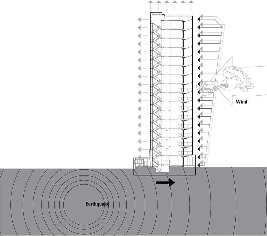
When we consider a building’s structural system, we typically think first of how its vertical supports and horizontal spanning assemblies are designed to carry the dead and live loads imposed by the weight of its construction and occupancy. Just as critical to the building’s stability, however, is its resistance to a combination of environmental conditions, such as wind, earthquake, earth pressure, and temperature, which can destabilize its gravity load-carrying elements. Of these, the forces exerted on a structure by wind and earthquakes are of primary concern in this chapter. Wind and earthquakes subject a structure to dynamic loading, often with rapid changes in magnitude and point of application. Under a dynamic load, a structure develops inertial forces in relation to its mass, and its maximum deformation does not necessarily correspond to the maximum magnitude of the applied force. Despite their dynamic nature, wind and earthquake loads are often treated as equivalent static loads acting in a lateral manner.
Wind
Wind loads result from the forces exerted by the kinetic energy of a moving mass of air, which can produce a combination of direct pressure, negative pressure or suction, and drag forces on buildings and other obstacles in its path. Wind forces are typically assumed to be applied normal, or perpendicular, to the affected surfaces of a building.
Earthquakes
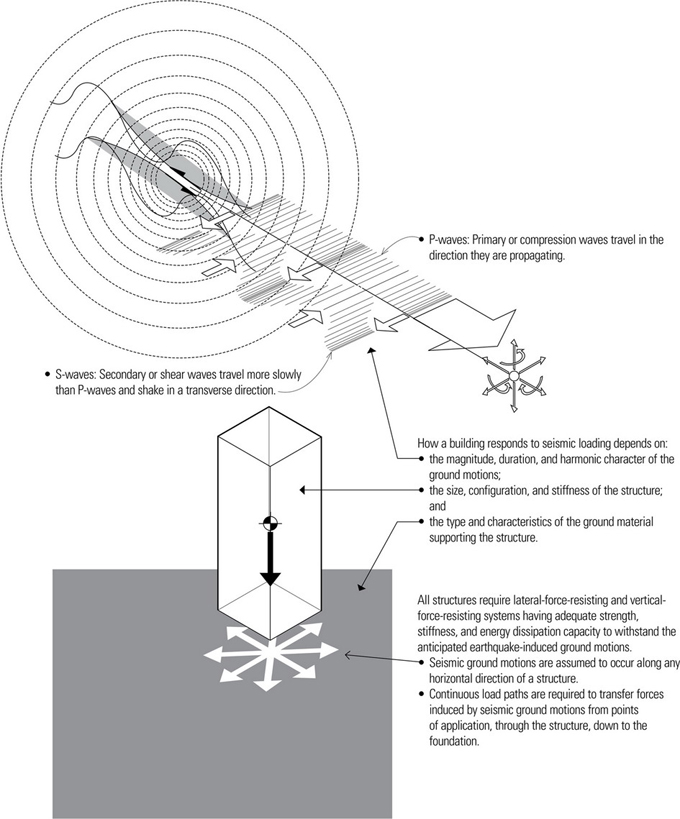
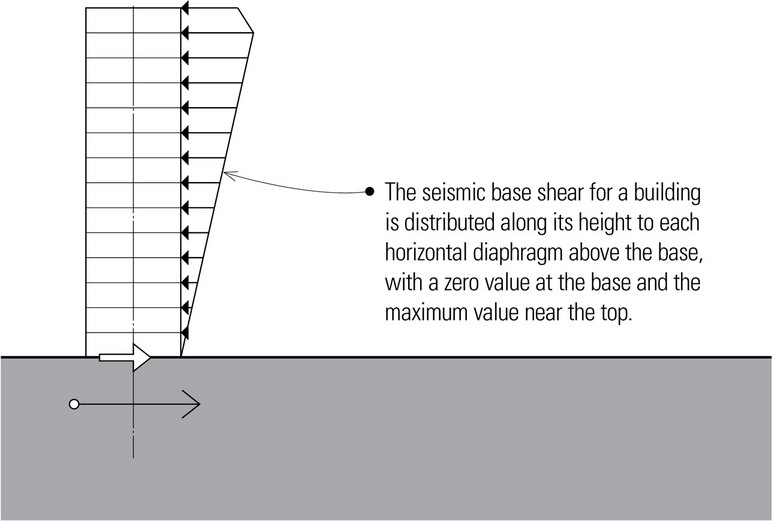
Seismic forces result from the vibratory ground motions of an earthquake, which can cause a building’s base to move suddenly and induce shaking of the structure in all directions simultaneously. While seismic ground motions are three-dimensional in nature and have horizontal, vertical, and rotational components, the horizontal component is considered to be the most important in structural design. During an earthquake, the mass of a building’s structure develops an inertial force as it tries to resist the horizontal ground acceleration. The result is a shear force between the ground and the building’s mass, which is distributed to each floor or diaphragm above the base.
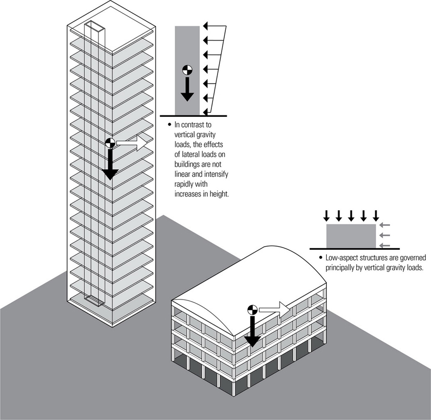
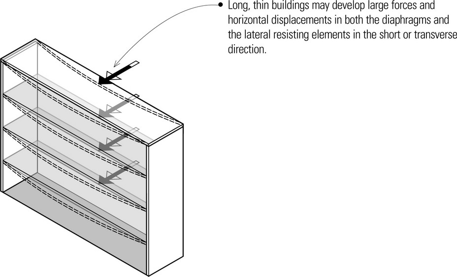
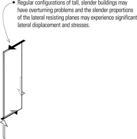
All buildings are subject to lateral loading from wind and earthquakes. The structural systems of tall or slender buildings, however, tend to be dominated by the need to resist lateral forces, which can impose large bending moments on and cause lateral displacement of their vertical members.
The structural design of buildings having a low aspect ratio, on the other hand, is predominantly governed by vertical gravity loads. Lateral loads due to wind and earthquakes have a relatively small effect on the sizing of members, but they cannot be ignored.
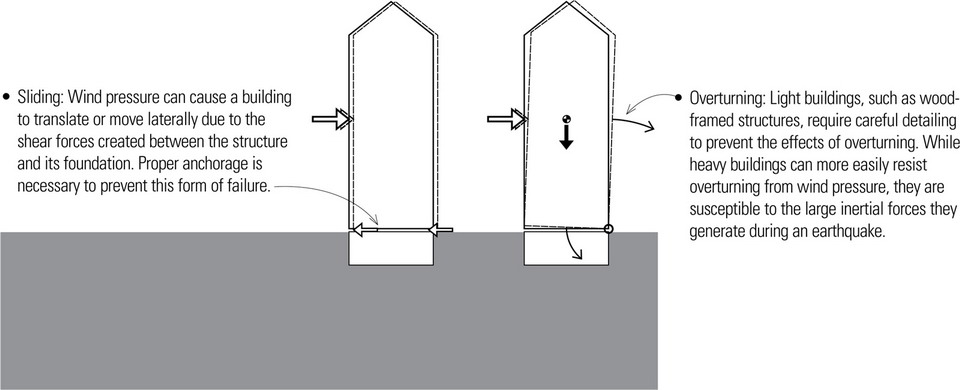
Also, while both wind and earthquakes exert lateral loads on all buildings, they differ in how the lateral forces are applied. Perhaps the most significant of these differences is the inertial nature of seismic forces, which causes the applied forces to increase with the weight of a building. Weight is therefore a major liability in seismic design. In responding to wind forces, however, a building can use its weight to advantage to resist sliding and overturning.
Likewise, a relatively stiff building subjected to wind forces responds favorably because its amplitude of vibration is small. However, a seismically loaded building tends to exhibit a better response if its structure is flexible, enabling it to dissipate some of the kinetic energy and moderate the resulting stresses through movement.
WIND
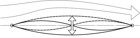
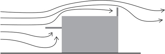
Wind is a moving mass of air. Buildings and other structures represent obstacles that deflect or impede the wind, converting the kinetic energy of the moving air mass into the potential energy of pressure.
Wind pressure increases as a function of wind velocity. The average mean wind velocity for any particular area, measured over a long period of time, generally increases with height. The rate of increase of the mean velocity is also a function of the ground roughness and the interference offered by surrounding objects that include other buildings, vegetation, and land forms.
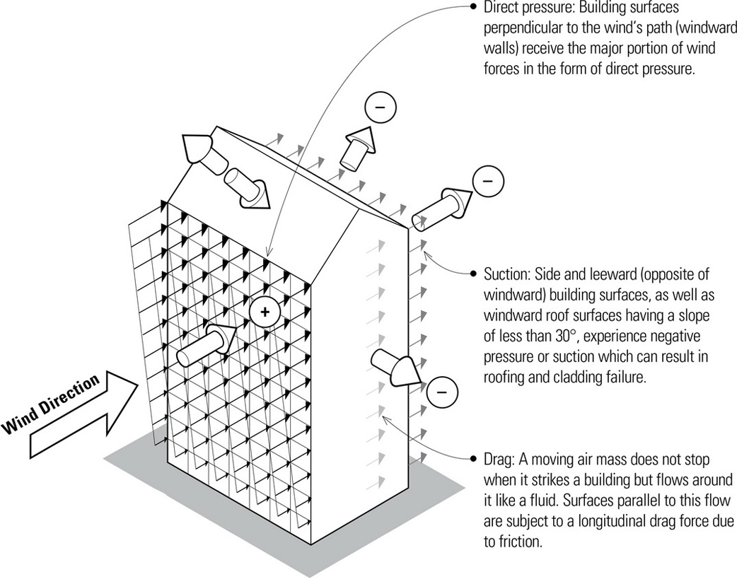
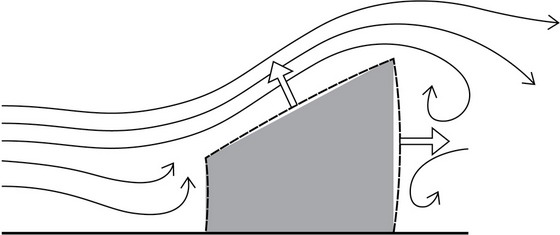
The primary effect of wind on buildings are the lateral forces it places on the entire structure and, in particular, on the exterior cladding. The net effect is a combination of direct pressure, negative pressure or suction, and drag forces. Wind pressure can also cause a building structure to slide as well as overturn.
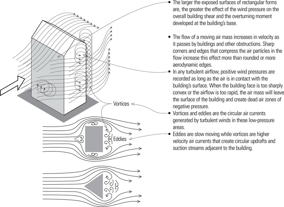
- The overturning force produced by wind pressure can be amplified by an increase in either wind velocity or exposed building surfaces.
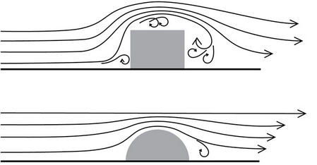
Shape and form can increase or decrease the effects of wind pressure on a building. For example, aerodynamically shaped buildings, such as rounded or curved forms, generally result in lower wind resistance than rectangular buildings with flat surfaces.
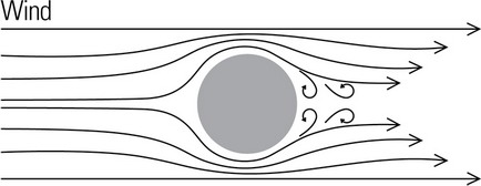
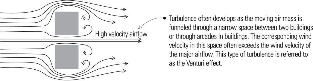
- The presence of turbulence can exacerbate the effects of wind on a building. One example is the harmonic effects that can cause unacceptable movement or flutter when the fundamental period of vibration caused by the wind coincides with the natural period of the structure.
- Buildings with open sides or configurations with recesses or hollows that capture the wind are subject to larger design wind pressures.
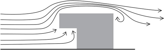
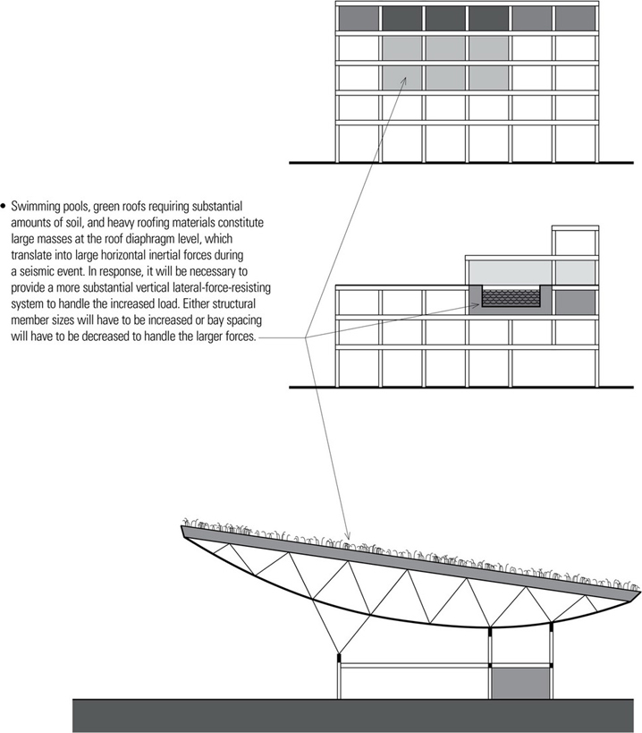
- Building projections, such as parapets, balconies, canopies, and overhangs, are subject to increased localized pressures from moving air masses.
- Wind pressure can subject very tall walls and long spanning rafters to large bending moments and deflection.
Wind can produce dynamic loading on tall, slender structures that exceeds typical design levels. The efficient design of structural systems and cladding for tall buildings requires knowledge of how wind forces impact their slender forms. Structural designers use wind tunnel tests and computer modeling to determine the overall base shear, overturning moment, as well as the floor-by-floor distribution of wind pressure on a structure, and to gather information about how the building’s motion might affect occupants’ comfort.
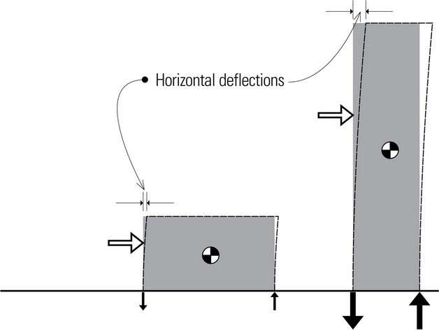
- Tall, slender buildings with a high aspect (height-to-base width) ratio experience larger horizontal deflections at their tops and are more susceptible to overturning moments.
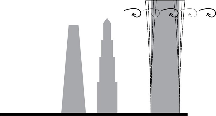
- Short-term gust velocities can also produce dynamic wind pressures that create additional displacement. For tall, slender buildings, this gust action may dominate and produce a dynamic movement called gust buffeting, which results in oscillation of the slender structure.
- Building forms that taper expose less surface area to the wind as they rise, which helps counteract the increasing wind velocities and pressures experienced higher up.
- For more information on tall building structures, see Chapter 7.
EARTHQUAKES
An earthquake consists of a series of longitudinal and transverse vibrations induced in the earth’s crust by the abrupt movement of plates along fault lines. The shocks of an earthquake propagate along the earth’s surface in the form of waves and attenuate logarithmically with distance from its source. While these ground motions are three-dimensional in nature, their horizontal components are considered to be the more critical in structural design; the vertical load-carrying elements of a structure usually have considerable reserve for resisting additional vertical loads.
The overall tendency of a building subjected to an earthquake is to vibrate as the ground shakes. Seismically induced shaking affects a building in three primary ways: inertial force, overturning, and fundamental period of vibration.
Inertial Force
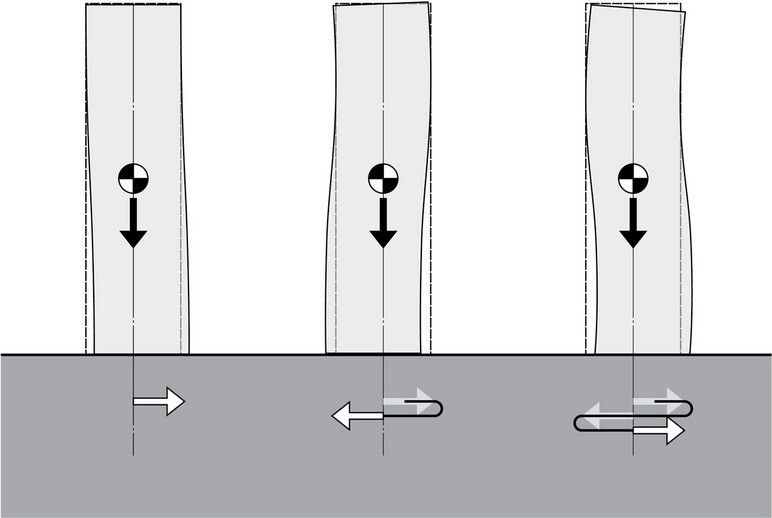
- The first response of a building during an earthquake is to not move at all due to the inertia of its mass. Almost instantaneously, however, the ground acceleration causes the building to move at the base, inducing a lateral load on the building and a shear force at the base (seismic base shear). The inertial force in the building opposes the base shear but both forces reverse directions as the building vibrates back and forth.
- From Newton’s second law, the inertial force is equal to the product of mass and acceleration.
- Inertial forces can be lessened by reducing the building’s mass. Therefore, lightweight construction is advantageous in seismic design. Light buildings, such as wood-frame houses, generally perform well in earthquakes, while heavy masonry structures are susceptible to significant damage.
- Seismic base shear is the minimum design value for the total lateral seismic force on a structure assumed to act in any horizontal direction.
- For regular structures, low irregular structures, and structures at low seismic risk, seismic base shear is computed by multiplying the total dead load of the structure by a number of coefficients to reflect the character and intensity of the ground motions in the seismic zone, the soil profile type underlying the foundation, the type of occupancy, the distribution of the mass and stiffness of the structure, and the fundamental period—the time required for one complete oscillation—of the structure.
- A more complex dynamic analysis is required for high-rise structures, structures with irregular shapes or framing systems, or for structures built on soft or plastic soils susceptible to failure or collapse under seismic loading.
Overturning Moment
- Any lateral load applied at a distance above grade generates an overturning moment at the base of a structure. For equilibrium, the overturning moment must be counterbalanced by an external restoring moment and an internal resisting moment provided by forces developed in column members and shear walls.
Fundamental Period of Vibration
The natural or fundamental period of a structure (T) varies according to its height above the base and its dimension parallel to the direction of applied forces. Relatively stiff structures oscillate rapidly and have short periods while more flexible structures oscillate more slowly and have longer periods.
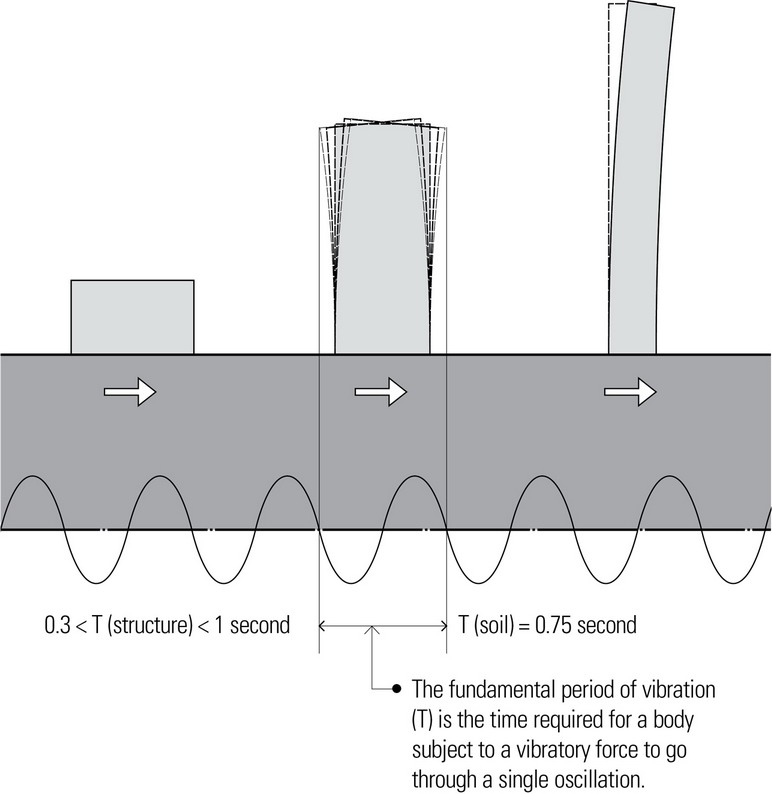
As seismic vibrations propagate through the ground material underlying a building structure, they may be either amplified or attenuated, depending on the fundamental period of the material. The fundamental period of ground material varies from approximately 0.40 seconds for hard soil or rock up to 1.5 seconds for soft soil. Very soft soil may have periods of up to 2 seconds. Earthquake shaking tends to be greater in a building situated on soft ground than in one built over hard ground. If the soil’s period falls within the range of the building’s period, it is possible for this correspondence to create a condition of resonance.
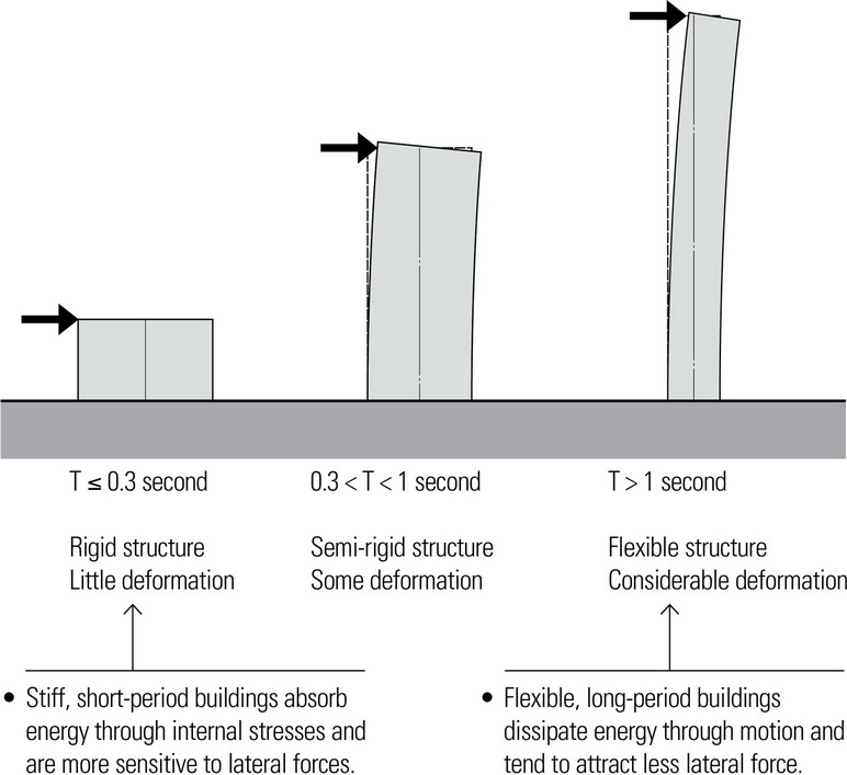
Any amplification in building vibration is undesirable. A structural design should ensure that the building period does not coincide with the period of the supporting soil. Short, stiff (short-period) buildings sited on soft (long-period) ground would be appropriate as well as tall buildings (long-period) built on hard, stiff (short-period) soil.
Damping, ductility, and strength-stiffness are three characteristics that can help a structure resist and dissipate the effects of seismically-induced motion.
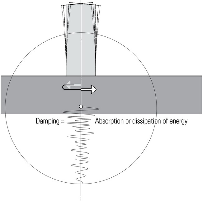
Damping
Damping refers to any of several means of absorbing or dissipating energy to progressively diminish successive oscillations or waves of a vibrating structure. For specific types of damping mechanisms, see pages 302–304. In addition to these damping methods, a building’s non-structural elements, connections, construction materials, and design assumptions can provide damping characteristics that greatly reduce the magnitude of the building’s vibration or swaying during an earthquake.

Ductility
Ductility is the ability of a structural member to deform several times the design deformation at its flexural yield capacity, which allows excessive loads to be distributed to other structural members or to other parts of the same member. Ductility is an important source of reserve strength in buildings that allow materials like steel to distort considerably without breaking, and in doing so, to dissipate the energy of the earthquake.
Strength & Stiffness
Strength is the ability of a structural member to resist a given load without exceeding the safe stress of the material. Stiffness, on the other hand, is a measure of the structural member’s ability to control deformation and limit the amount of its movement under loading. Limiting movement in this way helps to minimize the detrimental effects on the non-structural components of a building, such as cladding, partitions, hung ceilings and furnishings, as well as on the comfort of the building’s occupants.
LATERAL-FORCE-RESISTING MECHANISMS
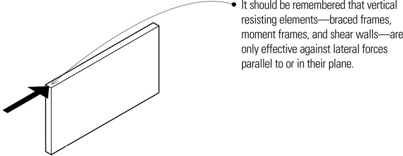
In general, there are three basic mechanisms commonly used, alone or in combination, for assuring the lateral stability of a building. They are braced frames, moment frames, and shear walls. Note that all of these lateral-force-resisting mechanisms are only effective against in-plane lateral forces. They cannot be expected to resist lateral forces perpendicular to their planes.
Braced Frames
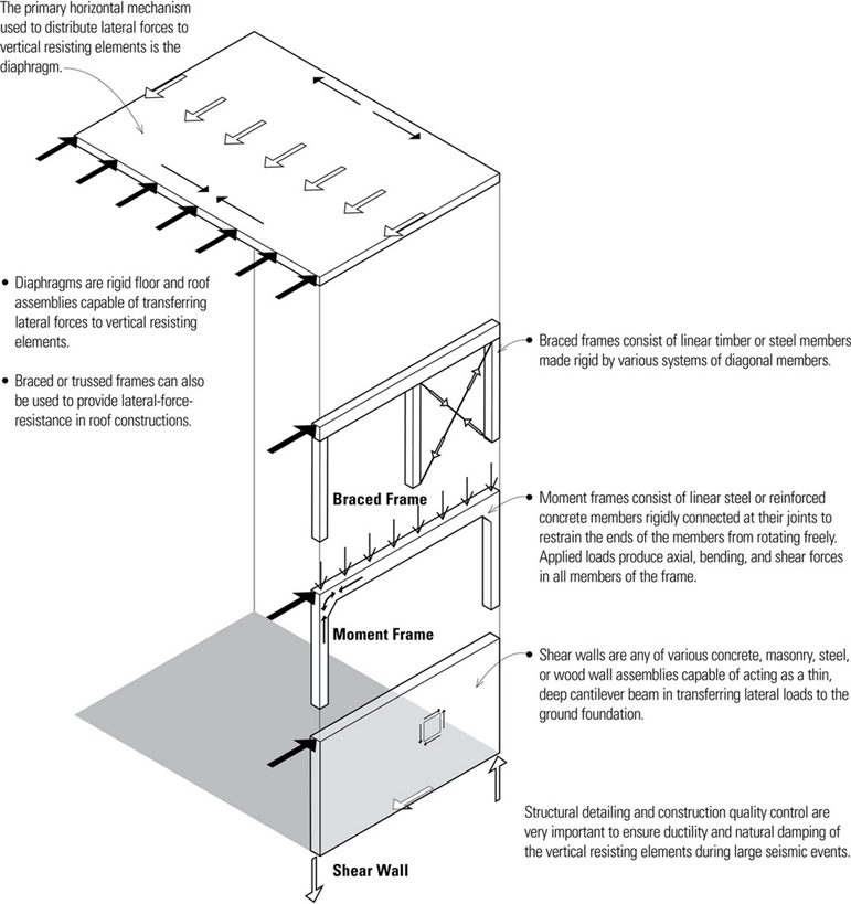
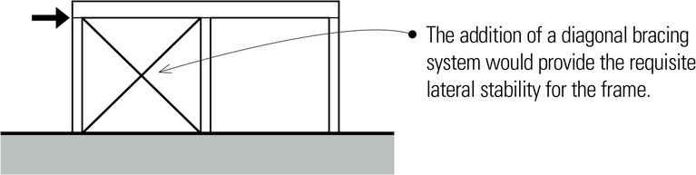
Braced frames consist of column-and-beam frames made rigid with a system of diagonal members that create stable triangular configurations. Examples of the great variety of bracing systems in use are:
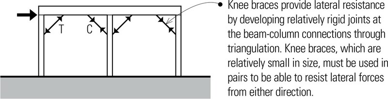
- Knee bracing
- Diagonal bracing
- Cross bracing
- V-bracing
- K-bracing
- Eccentric bracing
- Lattice bracing
Braced frames may be located internally within a building to brace a core or a major supporting plane, or be placed in the plane of the exterior walls. They may be concealed in walls or partitions or be exposed to view, in which case it establishes a strong structural expression.
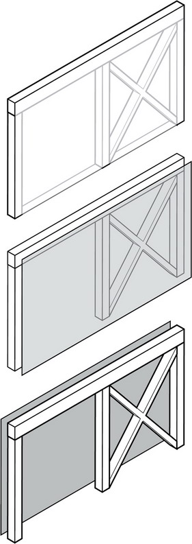
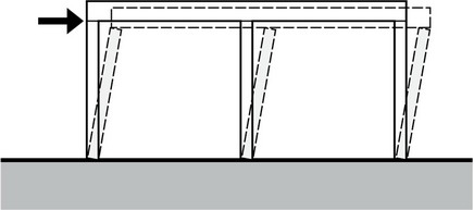
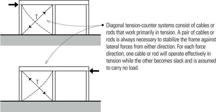
- The four-hinged quadrilateral is inherently unstable, however, and would be unable to resist a laterally applied load.
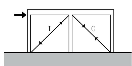
Single diagonal braces must be able to handle both tension and compression. The size of a single diagonal brace is determined more by its resistance to buckling under compression, which, in turn, is related to its unsupported length.
- The relative magnitude of the horizontal and vertical components in a diagonal brace result from the slope of the brace. The more vertical the diagonal brace, the stronger it will need to be to resist the same lateral load.
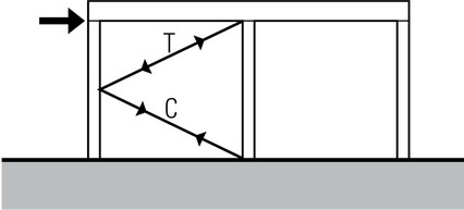
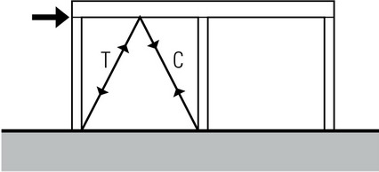
- K-bracing consists of a pair of diagonal braces that meet near the midpoint of a vertical frame member. Each diagonal brace can be subject to either tension or compression, depending on the direction of the lateral force acting on the frame.
- V-bracing consists of a pair of diagonal braces that meet near the midpoint of a horizontal frame member. As with K-bracing, each of the diagonals can be subject to either tension or compression, depending on the direction of the lateral force.
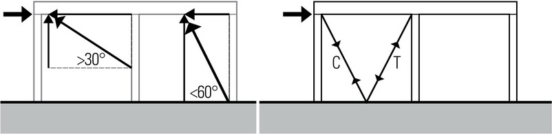
- The relative magnitude of the horizontal and vertical components in a diagonal brace result from the slope of the brace. The more vertical the diagonal brace, the stronger it will need to be to resist the same lateral load.
- Chevron bracing is similar to V-bracing but its orientation allows for passage through the space below the inverted V.
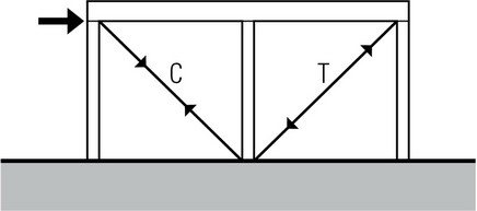
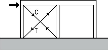
- X-bracing consists of a pair of diagonals. As in the previous examples, each of the diagonals can be subject to either tension or compression, depending on the direction of the lateral force. A certain degree of redundancy is achieved if each diagonal alone is capable of stabilizing the frame.
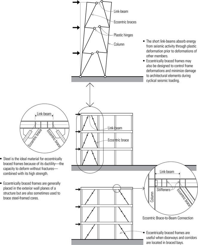
Eccentric Bracing
Eccentrically braced frames combine the strength and stiffness of braced frames with the inelastic (plastic) behavior and energy dissipation characteristic of moment frames. They incorporate diagonal braces that connect at separate points to beam or girder members, forming short link-beams between the braces and column members or between two opposing braces. The link-beams act as fuses to limit large forces from being exerted on and overstressing other elements in the frame.
The expected magnitude of seismic loads and the conservative nature of building codes make it necessary to assume some yielding of a structure during large earthquakes. However, in zones of high seismic risk, such as California, designing a building to remain entirely elastic during a large earthquake would be cost-prohibitive. Because steel frames have the ductility to dissipate large amounts of seismic energy and maintain stability even under large inelastic deformations, eccentrically braced steel frames are commonly used in seismic regions. They also provide the necessary stiffness to reduce drift produced by wind loads.
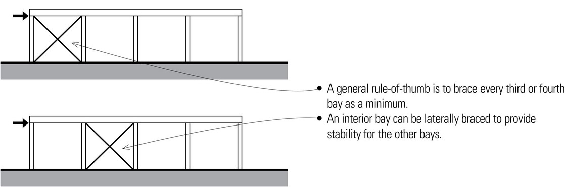
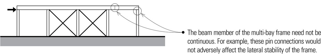
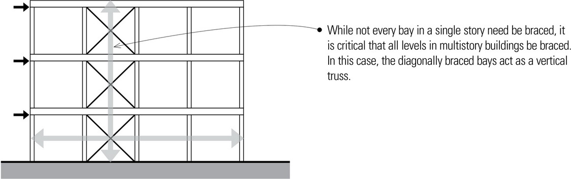
Multi-Bay Arrangements
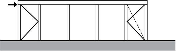
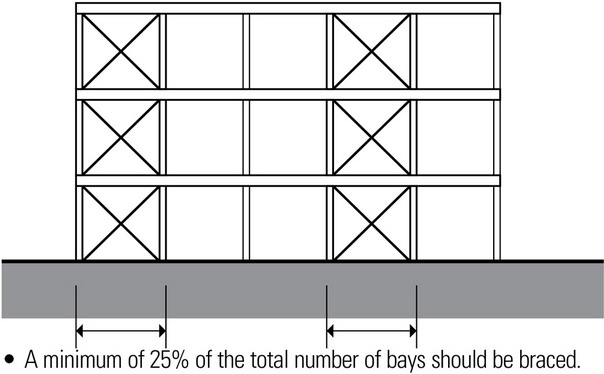
The amount of lateral bracing provided in multi-bay arrangements is a function of the lateral forces present; not all bays of a multi-bay arrangement need necessarily be braced.
- As more bays are braced, the member sizes of the bracing decrease and the lateral stiffness of the frame improves, resulting in less lateral displacement.
- Two internal bays can be braced to provide the exterior bays with lateral stability.
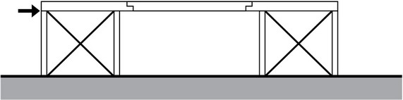
- Two exterior bays can be braced to provide an interior, column-free bay with lateral stability. The two overhanging beams support a simple beam.
- When the bay proportions would cause a single diagonal brace to be too steep or too flat, consider other forms of bracing to ensure effective bracing action.
- Note that in each of these illustrations, moment frames or shear walls may also be used in place of the braced frames shown.
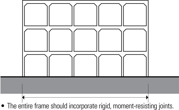
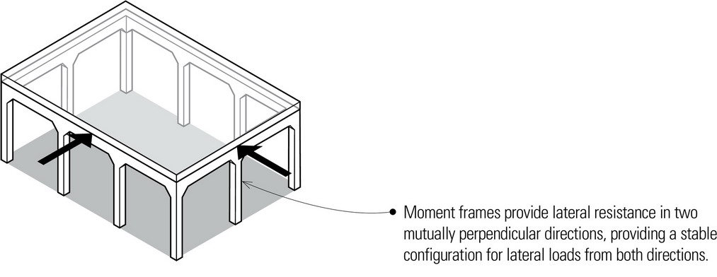
Moment Frames
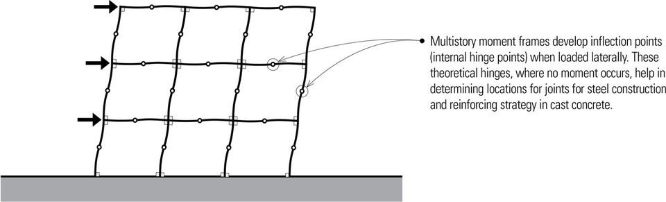
Moment frames, also known as moment-resisting frames, consist of floor or roof spanning members in plane with, and connected to, column members with rigid or semi-rigid joints. The strength and stiffness of a frame is proportional to the beam and column sizes, and inversely proportional to the column’s unsupported height and spacing. Moment frames require considerably larger beams and columns, especially at the lower levels of tall structures.
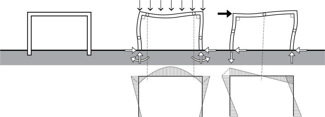
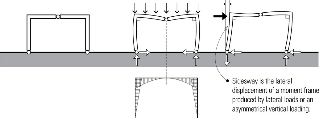
- Vertical and lateral loads applied to a moment frame produce axial, bending and shear forces in all members of the frame, since the rigid joints restrain the ends of the members from rotating freely. In addition, vertical loads cause a moment frame to develop horizontal thrusts at its base. A moment frame is statically indeterminate and rigid only in its plane.
- All elements in a moment frame are actually beam-columns, subject to combined bending and tensile or compressive stresses.
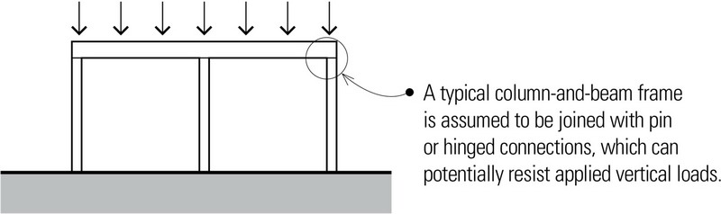
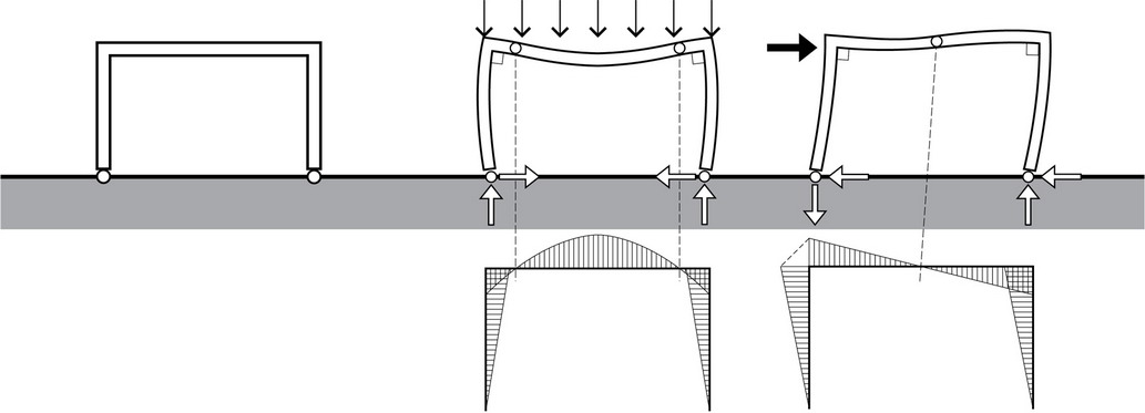
- A moment frame connected to its supports with pin joints is called a hinged frame. Bending moments due to gravity and lateral loads are largest at the beam-column connection. No bending moments occur at the supports since the columns are free to rotate about the pin connection.
- A structural assembly consisting of two rigid sections connected to each other and to its supports with pin joints are referred to as three-hinged frames. While more sensitive to deflection than either the fixed or hinged frame, the three-hinged frame allows a degree of prefabrication with a relatively simple field-pin connection.
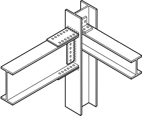
- Moment frames requiring moment-resisting capability are generally constructed of structural steel or reinforced concrete. The detailing of the beam-column connection is very important to assure rigidity of the joint.
- Structural steel beams and columns may be connected to develop moment-resisting action by means of welding, high-strength bolting, or a combination of the two. Steel moment-resisting frames provide a ductile system for resisting seismic forces after the elastic capacity of the system is exceeded.
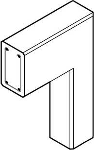
- Reinforced-concrete moment frames may consist of beams and columns, flat slabs and columns, or slabs with bearing walls. The inherent continuity that occurs in the monolithic casting of concrete provides a naturally occurring moment-resistant connection and thus enables members to have cantilevers with very simple detailing of the reinforcing steel.
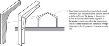
- In addition to structural steel, laminated timber can be used in fabricating the sections for three-hinged frames. Additional material is provided at the beam-column intersection for resisting the larger bending moments.
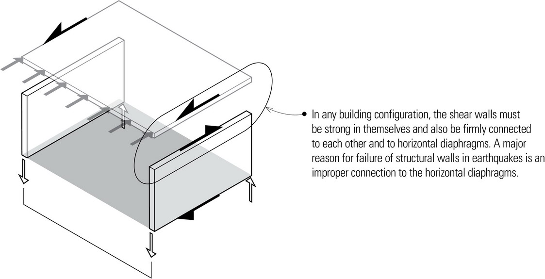
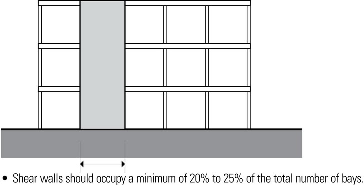
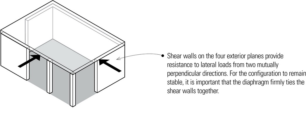
Shear Walls
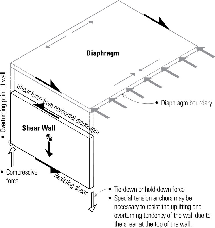
Shear walls are rigid vertical planes that are relatively thin and long. A shear wall may be considered analogous to a cantilever beam standing on end in a vertical plane and resisting the concentrated shear load delivered from the floor or roof diaphragm above.
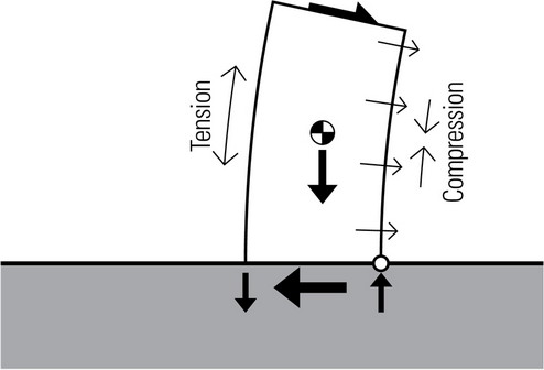
The shear wall is placed in equilibrium by the dead-load weight of the wall and the resisting couple created by the tension and compression at the wall edges or corners.
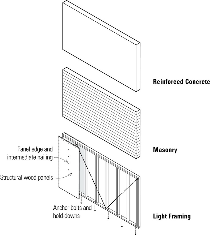
Shear walls may be constructed of:
- Cast-in-place, reinforced concrete
- Precast concrete
- Reinforced masonry
- Light-frame stud construction sheathed with structural wood panels, such as plywood, oriented-strand board (OSB), or diagonal board sheathing.
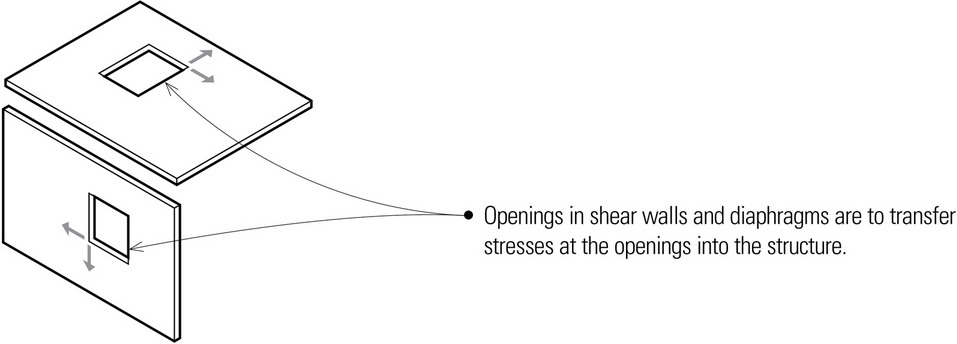
There are generally very few openings or penetrations in shear walls. If a shear wall does have regular penetrations, its structural action is intermediate between that of a shear wall and a moment-resisting frame.
- If two or more shear walls are connected with relatively rigid members, they are referred to as coupled shear walls.
Diaphragms
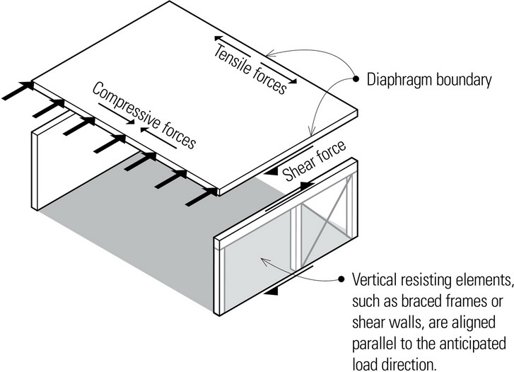
To resist lateral forces, buildings must be composed of both vertical and horizontal resisting elements. Vertical elements used to transfer lateral forces to the ground are braced frames, moment frames, and shear walls. The principal horizontal elements used to distribute lateral forces to these vertical resisting elements are diaphragms and horizontal bracing.
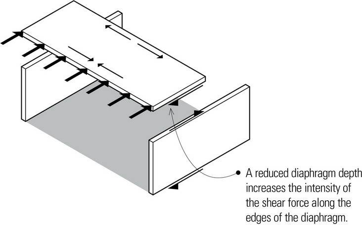
Diaphragms are typically floor and roof constructions that have the capacity to transfer lateral wind and seismic forces to vertical resisting elements. Using the steel beam as an analogy, diaphragms act as flat beams where the diaphragm itself acts as the web of the beam and its edges act as flanges. Although diaphragms are usually horizontal, they can be curved or sloped, as is frequently the case in constructing roofs.
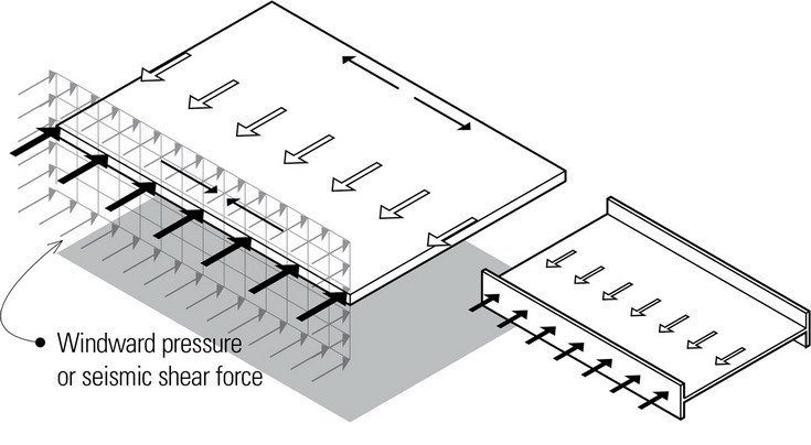
Structural diaphragms generally have tremendous strength and stiffness in their plane. Even when floors or roofs are somewhat flexible to walk on, they are extremely stiff in their own plane. This inherent stiffness and strength allows them to tie columns and walls at each level together and to provide lateral resistance to those elements that require bracing.
Diaphragms may be classified as either rigid or flexible. This distinction is important because it significantly affects how lateral loads are distributed from the diaphragm to the vertical resisting elements. The load distribution from rigid diaphragms to the vertical resisting elements is related to the stiffness of those vertical elements. Torsional effects can occur for rigid diaphragms that are connected to non-symmetrically arranged vertical resisting elements. Concrete slabs, metal decking with concrete fill, and some heavy-gauge steel decking are considered to be rigid diaphragms.
If a diaphragm is flexible, the in-plane deflections may be large and the load distribution to the vertical resisting elements is determined by the contributing load area of the diaphragm. Wood sheathing and light-gauge steel decking without a concrete fill are examples of flexible diaphragms.
Floor and roof diaphragms may be constructed of wood, metal, or concrete assemblies.
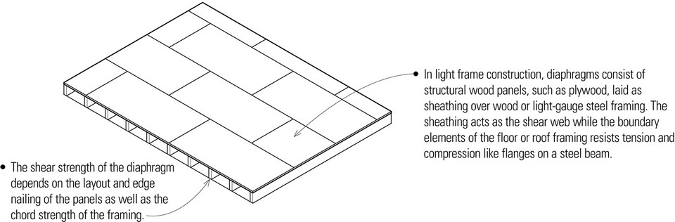
Light Framing with Sheathing
Metal Decking
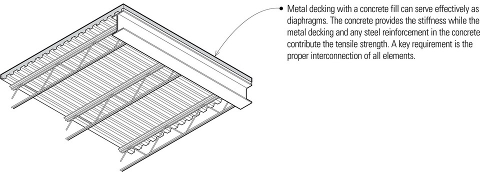
- Metal roof decking without a concrete fill can serve as a diaphragm but it is considerably more flexible and weaker than decking with a concrete fill.
Concrete Slabs
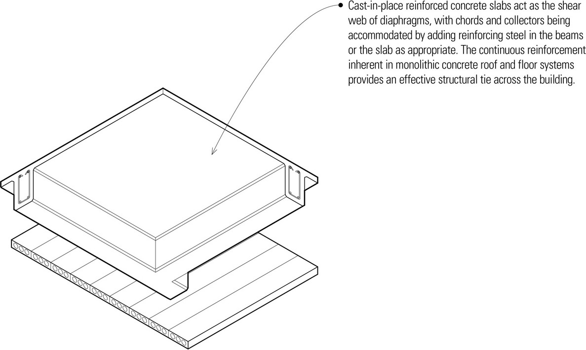
- When concrete slabs serve as diaphragms in steel-framed buildings, proper bonding or attachment of the slabs to the steel framing must be provided to stabilize the compression flange of the steel beam as well as to facilitate the transfer of diaphragm forces to the steel frame. This generally requires encasing the steel beams with concrete or providing welded stud connectors on the top flanges of the steel beams.
- Precast concrete floor and roof systems offer more of a challenge in providing a sound structural diaphragm. When diaphragm stresses are large, a cast-in-place topping slab may be placed over the precast elements. Without a topping slab, the precast concrete elements must be interconnected with adequate fasteners to transmit the shear, tensile, and compressive forces along the boundaries of the precast elements. These fasteners generally consist of welded steel plates or bars between inserts in adjacent panels.
LATERAL-FORCE-RESISTING SYSTEMS
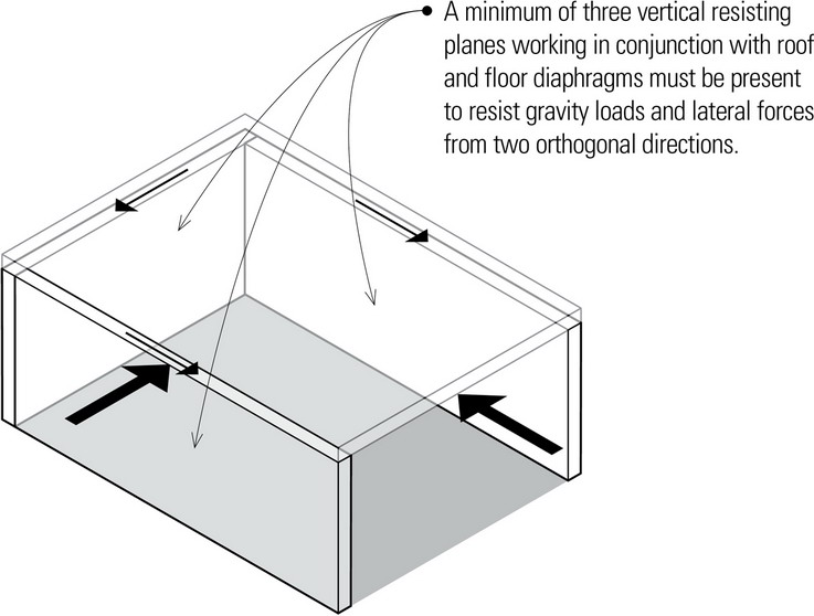
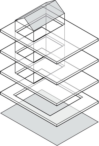
Buildings are three-dimensional structures, not simply a collection of two-dimensional planes. Their geometric stability relies on a three-dimensional composition of horizontal diaphragms and vertical resisting elements arranged and interconnected to work together in resisting lateral forces assumed to come from any horizontal direction. For example, as a building shakes during an earthquake, the inertial forces generated must be transmitted through the structure to the foundation via a three-dimensional lateral-force-resisting system.
Understanding how lateral-force-resisting systems operate is important in architectural design because they can significantly impact the shape and form of a building. Decisions about the type and location of the lateral-force-resisting elements to be used directly affect the organizational plan of the building and ultimately its final appearance.
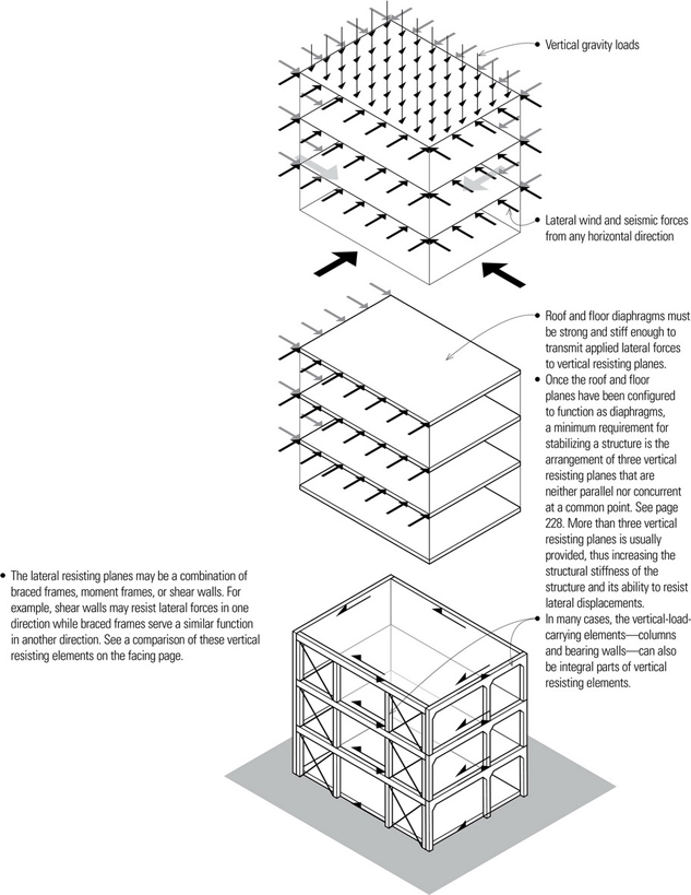
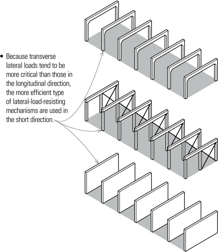
Lateral-force-resistance in the vertical planes of a building may be provided by braced frames, moment frames, or shear walls, used singly or in combination. These vertical resisting mechanisms, however, are not equivalent in terms of stiffness and efficiency. In some cases, only a limited portion of a structural frame need be stabilized. To the left is illustrated the relative lengths required to brace a five-bay frame by the various types of vertical resisting mechanisms.
Braced Frames
- Braced frames have high strength and stiffness and are more effective than moment frames in resisting racking deformation.
- Braced frames use less material and employ simpler connections than moment frames.
- Lower floor-to-floor heights are possible with braced frames than with moment frames.
- Braced frames can become an important visual component of a building’s design. On the other hand, braced frames can interfere with access between adjacent spaces.
Moment Frames
- Moment frames offer the most flexibility for visual and physical access between adjacent spaces.
- Moment frames have good ductility if their connections are properly detailed.
- Moment frames are less efficient than braced frames and shear walls.
- Moment frames require more material and labor to assemble than braced frames.
- Large deflections during an earthquake can damage non-structural elements of a building.
Shear Walls
- Reinforced concrete or masonry walls are effective in absorbing energy if firmly tied to floor and roof diaphragms.
- Shear walls must be well proportioned to avoid excessive lateral deflection and high shear stresses.
- Avoid high aspect (height-to-width) ratios.
Building Configuration
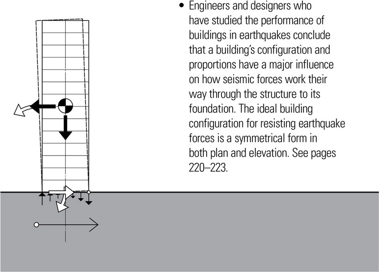
Building configuration refers to the three-dimensional composition of lateral-force-resisting mechanisms in a structure. Decisions concerning the location and arrangement of these mechanisms—as well as their size and shape—can have a significant influence on the performance of a structure, especially when subjected to seismic forces during an earthquake.
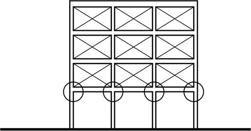
Regular Configurations
Building codes base seismic forces on the assumption of a regular configuration of resisting systems providing a balanced response to an equally balanced distribution of lateral forces. In addition, regular configurations are generally characterized by symmetrical plans, short spans, redundancy, equal floor heights, uniform sections and elevations, balanced resistance, maximum torsional resistance, and direct load paths.
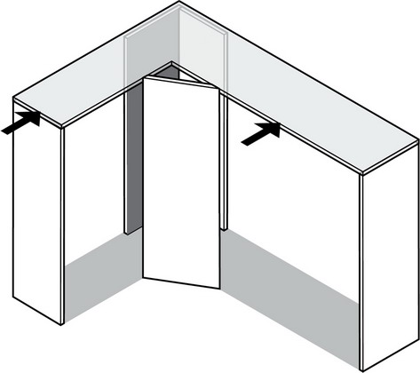
Irregular configurations, such as discontinuous diaphragms or L- or T-shaped buildings, can develop severe stress concentrations and a twisting motion (torsion) that is very difficult to resist. See Reentrant Corners.
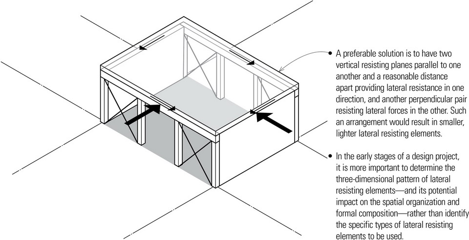
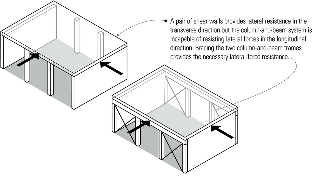
The arrangement of vertical resisting planes in relation to one another is crucial to the ability of a building structure to resist lateral loads from multiple directions. Balanced and symmetrical layouts of lateral-force-resisting elements are always preferable to avoid the torsional effects that occur when the centers of building mass and resistance are not concurrent.
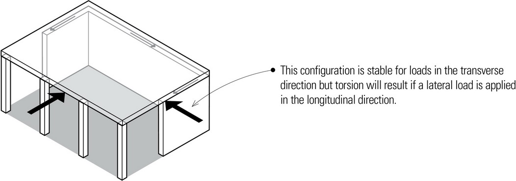
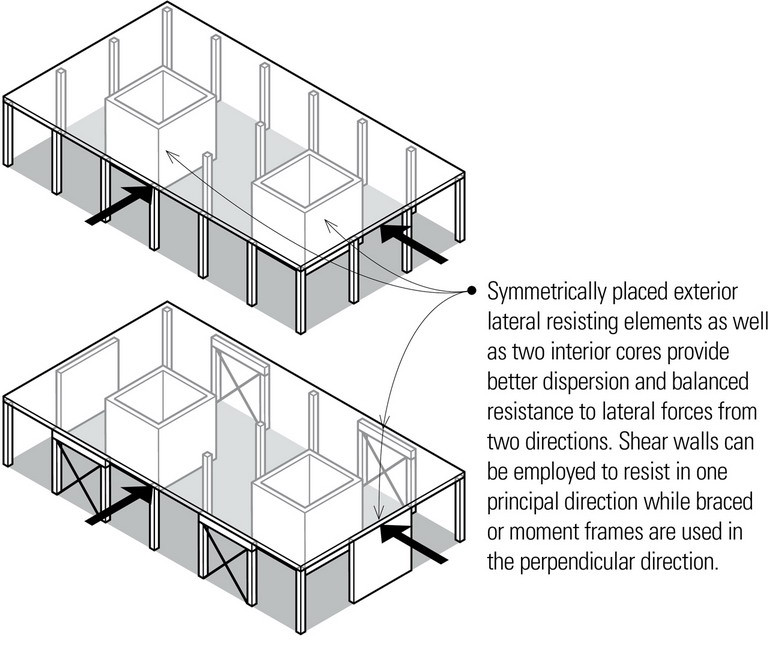
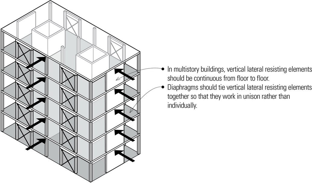
The preceding page illustrated stable configurations of relatively small-scale structures. In larger buildings, it is even more critical that lateral resisting elements be located strategically to resist lateral loads from any horizontal direction and to minimize the potential of torsional moments and displacements. For multistory buildings with square or rectangular grids, the vertical resisting elements are ideally placed in mutually perpendicular planes throughout the structure and are continuous from floor to floor.
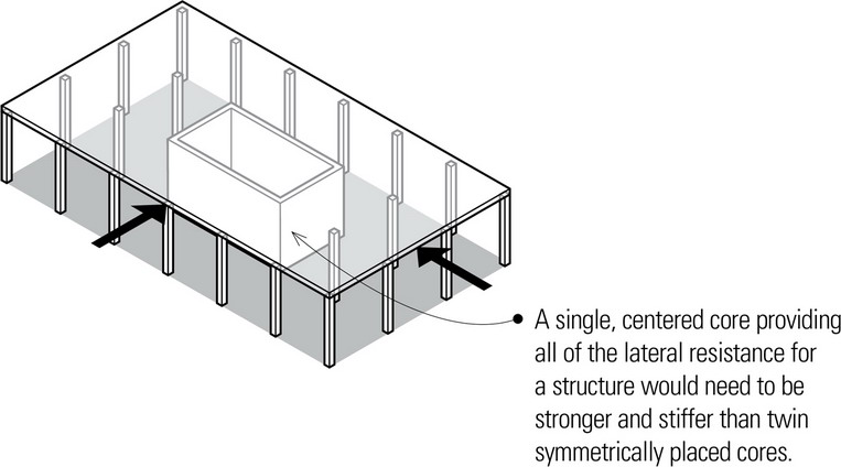
How the vertical resisting elements are dispersed affects the effectiveness of a lateral-force-resisting strategy. The more concentrated the lateral resisting elements are in a building, the stronger and stiffer they must be. Conversely, the more dispersed and balanced the arrangement of lateral resisting elements, the less stiff each lateral resisting element can be.
Also critical to the performance of a lateral strategy that consists of dispersed resisting elements is the degree to which they are tied together by diaphragms so that they work in unison rather than individually. In the case where the lateral resisting elements are concentrated, for example, the horizontal diaphragms must be able to transfer lateral forces from the exterior surfaces to these internal resisting elements.
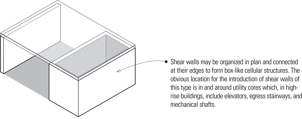
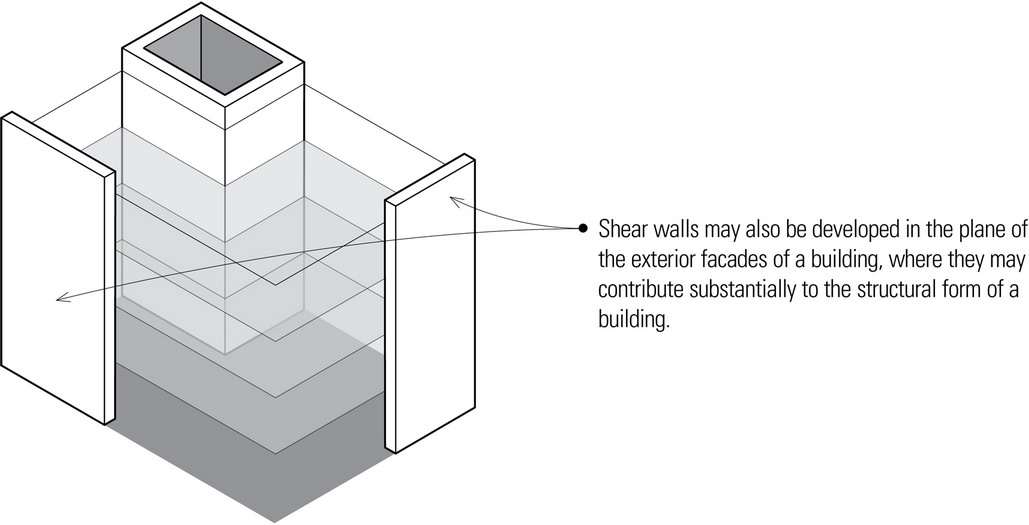
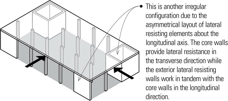
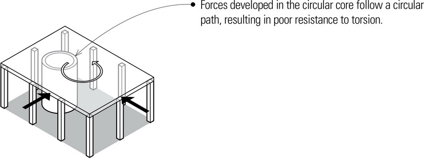
In multistory buildings the service cores housing elevators, stairways, and mechanical shafts can be constructed with shear walls or braced frames. These core walls can be viewed as resisting lateral forces from each of the planar directions or they can be viewed as forming a three-dimensional structural tube able to stabilize and stiffen the building structure against lateral loads. Because core shafts are normally rectangular or circular in cross section, their tubular action offers an efficient means for resisting moments and shear from all directions. A combination of structural cores and lateral resisting planes can offer excellent resistance to lateral forces when placed strategically and connected to one another by horizontal diaphragms at each floor level.
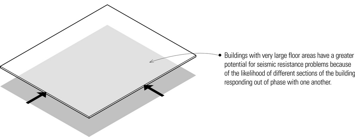
Another aspect of configuration that affects the seismic performance of building structures is their overall size and geometric proportions.
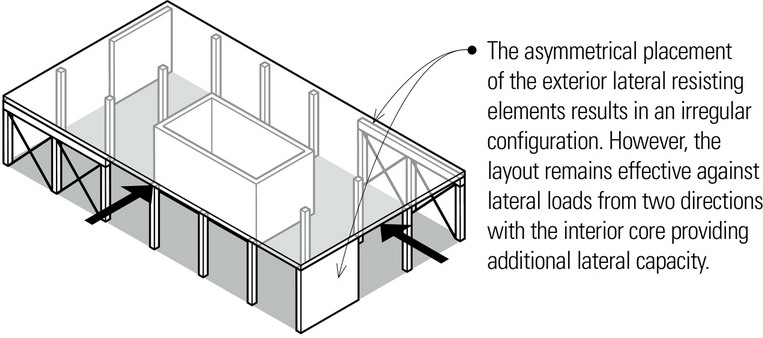
Irregular Configurations
It is inconceivable that all buildings will have regular configurations. Irregularities in plan and section often result from programmatic and contextual requirements, concerns, or desires. Unbalanced building layouts, however, can impact the stability of the structure under lateral loading and especially its susceptibility to damage in an earthquake. In the context of seismic design, irregular configurations vary both in importance and the extent to which a particular irregularity exists. When irregularities cannot be avoided, the designer should be aware of the possible seismic consequences and carefully detail the building structure in a way to ensure its proper performance.
Horizontal Irregularities
Horizontal irregularities include those arising from plan configurations, such as torsional irregularity, reentrant corners, nonparallel systems, diaphragm discontinuities, and out-of-plane offsets.
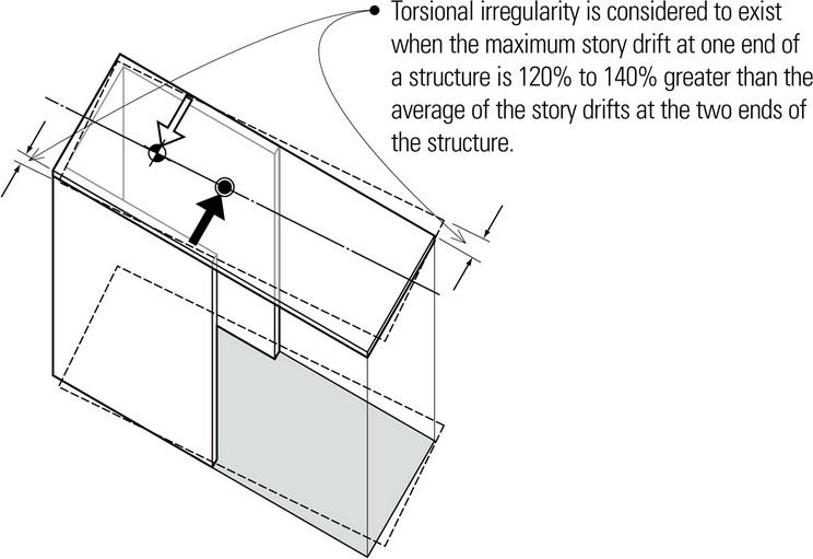
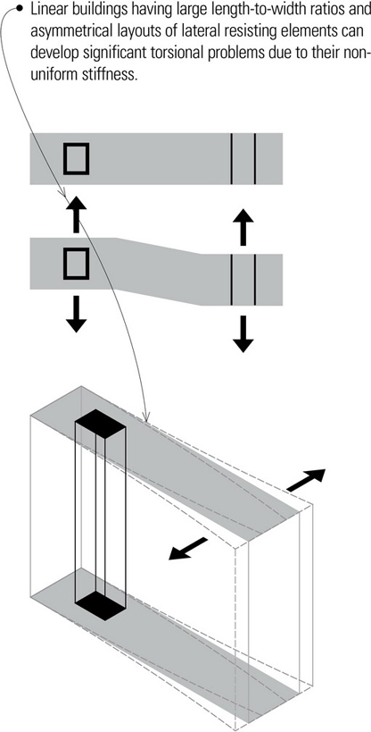
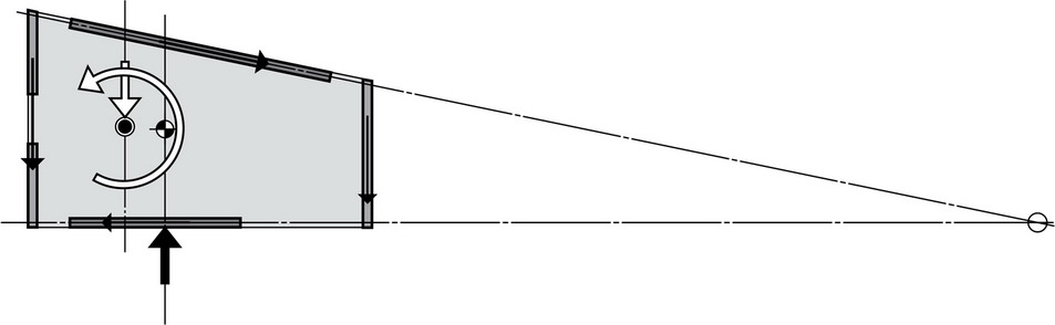
Torsional Irregularity
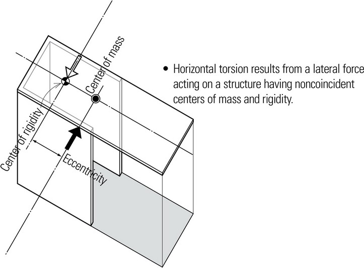
Variations in the perimeter strength and stiffness of a structure can produce an eccentricity or separation between its center of mass (the centroid of the lateral force) and its center of rigidity or resistance (the center of stiffness of the lateral-force-resisting elements of the system). The result is a horizontal twisting or torsion of the building, which can result in overstressing of structural elements and stress concentrations at certain locations, most often at reentrant corners. To avoid destructive torsional effects, structures should be arranged and braced symmetrically with centers of mass and rigidity as coincident as possible.
When a building plan is not symmetrical, the lateral-force-resisting system must be adjusted so that its center of stiffness or rigidity is proximate to the center of mass. If this is not possible, then the structure must be designed specifically to counter the torsional effects of the asymmetrical layout. An example would be distributing the bracing elements with stiffnesses that correspond to the distribution of the mass.
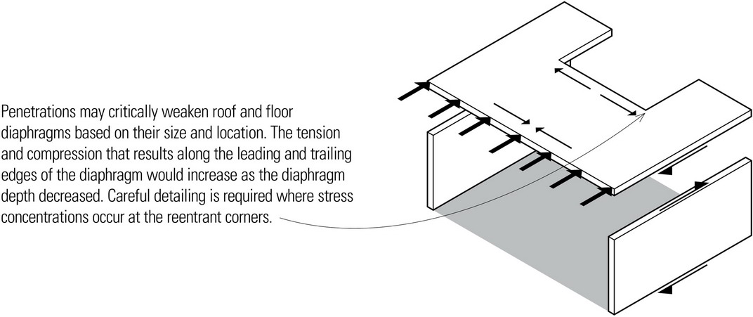
Reentrant Corners
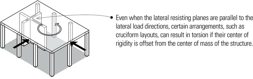
L-, T-, U-, and H-shaped buildings, as well as cruciform plan organizations, are problematic because areas of large stress concentration can develop at the reentrant corners—interior corners where building projections are greater than 15% of the plan dimension in a given direction.
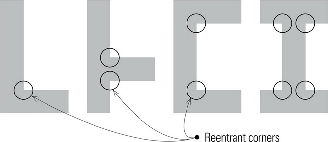
These building shapes tend to have differences in rigidity among the parts, which tends to produce differential motions between different portions of the structure, resulting in localized stress concentrations at the reentrant corners.
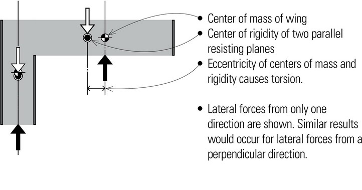
Stress concentrations and torsional effects at reentrant corners are interrelated. The centers of mass and rigidity of these configurations cannot geometrically coincide for all possible directions of seismic forces, thus resulting in torsion.
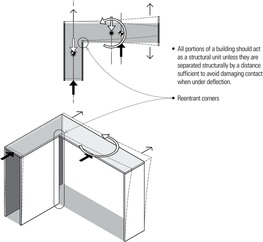
There are two basic approaches to dealing with the problem of reentrant corners:
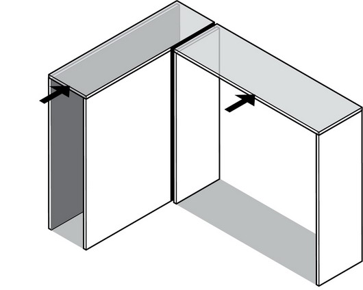
- Lateral forces from only one direction are shown. Similar results would occur for lateral forces from a perpendicular direction.
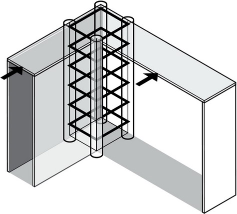
- One possible solution is to tie the two buildings firmly together so that the wings will respond better as a unit during a seismic event. Collector beams can be used at the intersection to transfer forces across the intersection core.
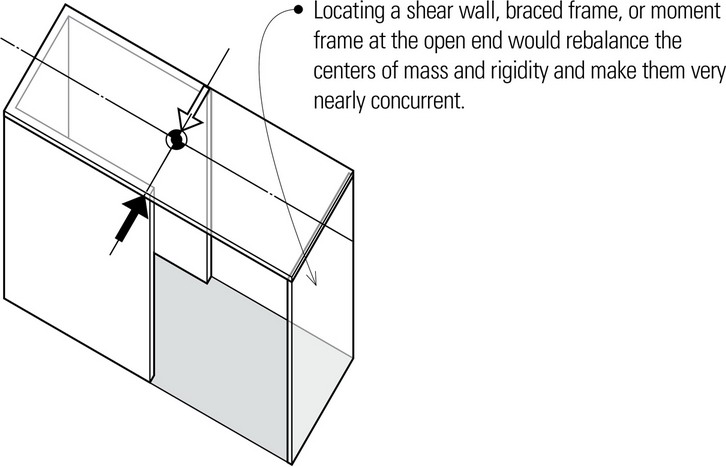
- Assuming the wings are tied together, another solution is to introduce full-height stiffening elements—shear walls, braced frames, or moment frames—at the free ends to reduce their displacement and lessen the torsional tendency of the building.
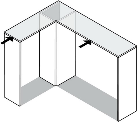
- Stress concentrations at reentrant corners can also be reduced by replacing the sharp corner with a splay to ease the flow of stress.
Nonparallel Systems
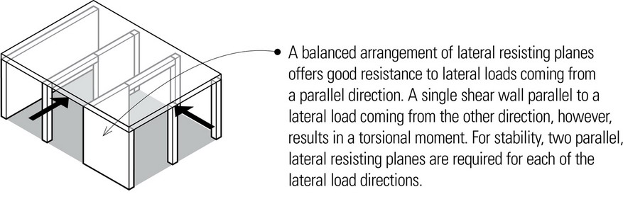
Nonparallel systems are structural layouts in which the vertical lateral-force-resisting elements are neither parallel nor symmetrical about the major orthogonal axes of the structure. The nonparallel resisting planes would not be able to resist the torsion resulting from the lateral load and the resisting shear forces in the wall planes parallel to the load.
Diaphragm Discontinuities
Diaphragms having significant variations in stiffness from one story to the next—as well as those incorporating large cutouts or open areas—represent another type of plan irregularity. These discontinuities affect how effectively the diaphragms are able to distribute lateral forces to vertical elements of the lateral-force-resisting system.
Out-of-Plane Offsets
Out-of-plane offsets are discontinuities in the path of vertical elements of the lateral-force-resisting system. Forces acting on a structure should flow with as much directness as possible along a continuous path from one structural element to the next and eventually be resolved through the foundation system to the supporting ground. When a vertical element of the lateral-force-resisting system is discontinuous, a horizontal diaphragm must be able to redistribute the horizontal shear forces to a vertical resisting element in the same or another plane.
Vertical Irregularities
Vertical irregularities arise from sectional configurations, such as soft stories, weak stories, geometric irregularities, in-plane discontinuities, and irregularities in mass or weight.
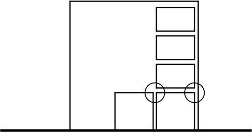
Soft Stories
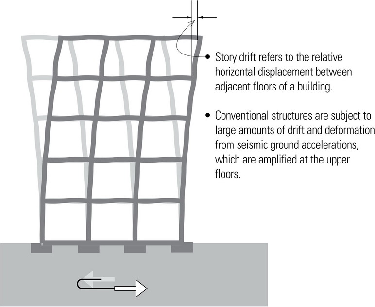
Soft stories have a lateral stiffness significantly less than that in the story above. A soft story can occur at any level but since seismic forces accumulate toward the base, the discontinuity in stiffness tends to be greatest between the first and second floor of a building. The reduced stiffness produces large deformations in the soft-story columns and generally results in a shear failure at the beam-column connection.
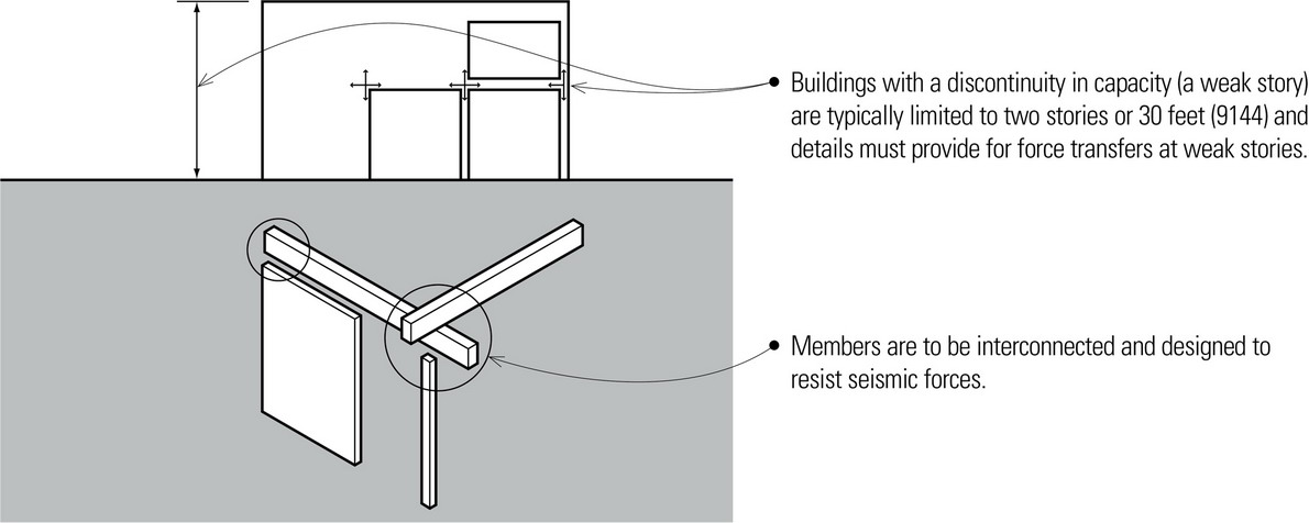
Weak Stories
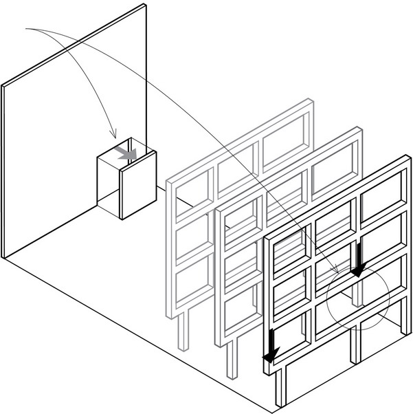
Weak stories are caused by the lateral strength of one story being significantly less than that in the story above. When shear walls do not line up in plan from one story to the next, the lateral forces are unable to flow directly downward through the walls from the roof to the foundation. An altered load path will redirect the lateral forces in an attempt to bypass the discontinuity, resulting in critical overstresses at locations of discontinuity. The discontinuous shear wall condition represents a special case of the soft first-story problem.
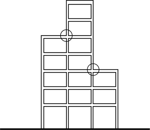
Geometric Irregularities
Geometric irregularities are caused by a horizontal dimension of the lateral-force-resisting system being significantly greater than that of an adjacent story. This vertical irregularity can cause the various parts of a building to have different and very complex responses. Special attention needs to be paid at the points of connection where changes in elevation occur.
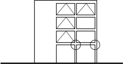
In-Plane Discontinuities
In-plane discontinuities create variations in stiffness in vertical lateral-force-resisting elements. Variations in stiffness should normally increase from the roof down to the base of a building. Seismic forces accumulate at each successive lower diaphragm level and become critical at the second floor level. Any reduction of lateral bracing at this level can result in large lateral deformations of the first-floor columns and very high shear stresses in the shear wall and columns.
Weight or Mass Irregularity
Weight or mass irregularity is caused by the mass of a story being significantly heavier than the mass of an adjacent story. Similar to the soft-story irregularity, the change in stiffness will result in a redistribution of loads that may cause stress concentrations at the beam-column joints and larger column displacements in the columns below.
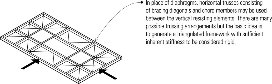
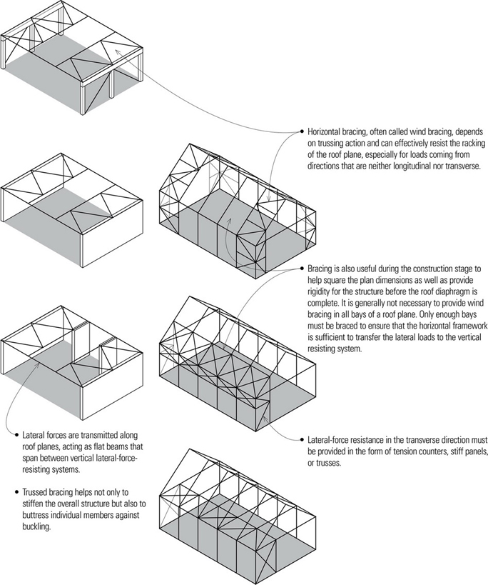
Horizontal Braced Framing
Occasionally, when the roof or floor sheathing is too light or flexible and unable to sustain diaphragm forces, the horizontal framework must be designed to incorporate bracing similar to that of braced wall frames. In steel-framed buildings, particularly industrial or warehouse structures with long-span trusses, the roof diaphragm is provided by diagonal steel bracing and struts. The most important consideration is to provide a complete load path from the lateral forces to the vertical resisting elements.
Base Isolation
Base isolation is a strategy involving the separation or isolation of the building from its foundation in such a way that it can absorb the shock of an earthquake. As the ground moves, the building moves at a lower frequency because the isolators dissipate a large part of the shock. In this approach, the building structure is decoupled from the horizontal components of the earthquake ground motion by interposing a layer with low horizontal stiffness between the structure and foundation, thereby reducing the resulting inertia force the structure must resist.
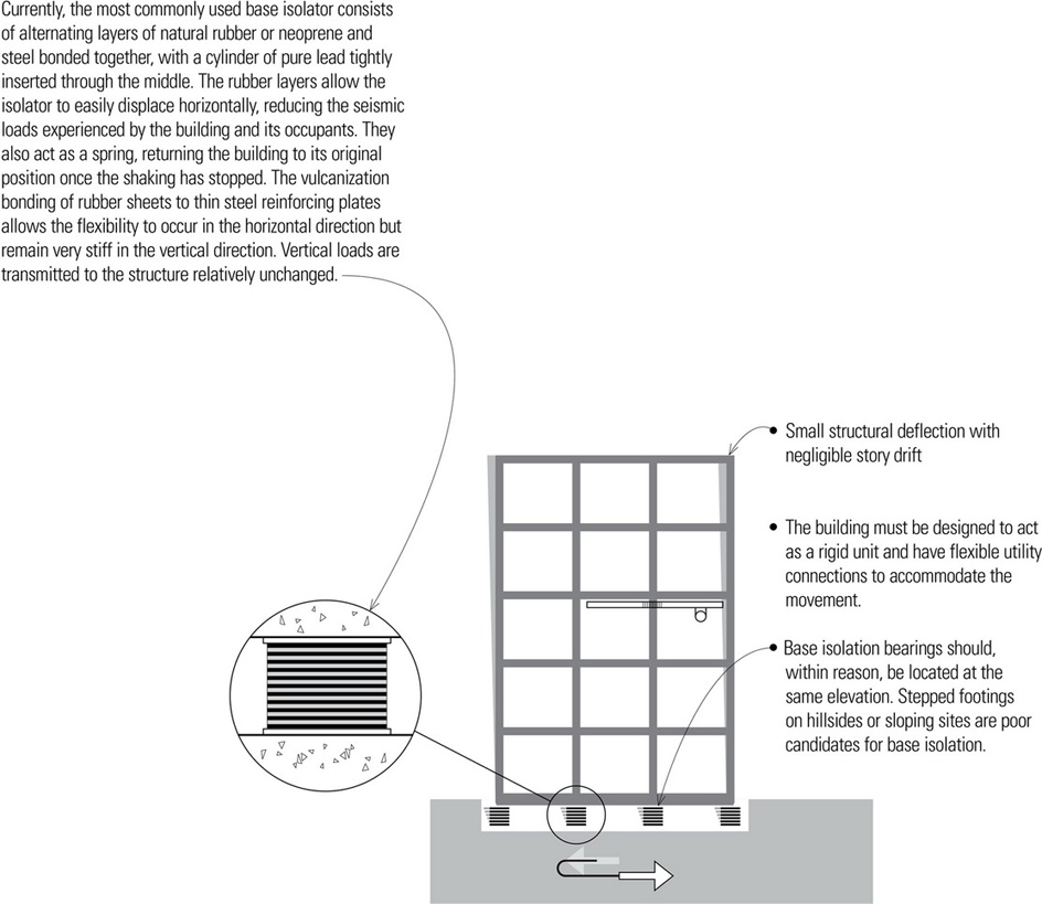
Base isolation systems are generally suitable for stiff buildings up to about seven stories in height; taller buildings would be subject to overturning, which base isolation systems cannot mitigate. Recently, however, taller buildings have benefited from base isolation. Buildings normally require the isolated period to be 2.5 to 3 times that of the typical non-isolated building.
Detailing of Building Components
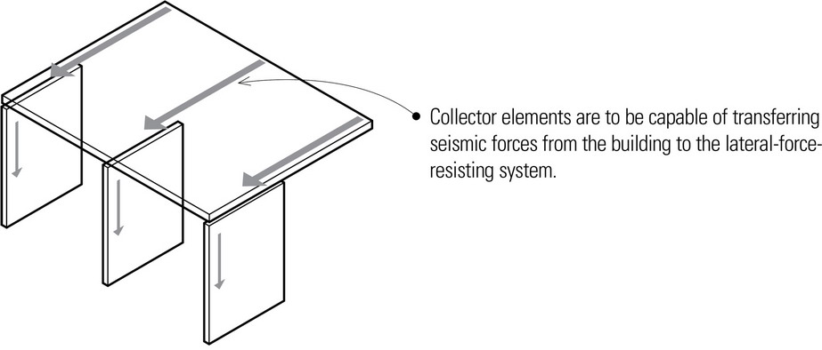
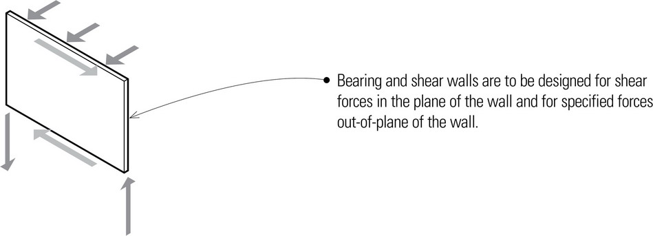
Building codes generally contain requirements for the design and detailing of the components making up the seismic-force-resisting systems of a building, such as diaphragms and shear walls, as well as addressing the problems associated with irregular building configurations. Among the details to be considered are:
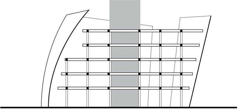
The effects of gravity and lateral loading apply to all structures, no matter what their shape or geometry may wish to convey. Even freeform buildings that appear to have no regularity to their structure often have relatively regular framing systems beneath their surface, or they may incorporate a nonrectilinear structural geometry that is inherently stable. There are a number of ways one can structure nonrectilinear, irregular, organic forms. The important issue is that these apparently free forms should have an underlying geometric or structural basis, even if not apparent to the eye, and that this basis incorporate the requisite lateral-force-resisting strategies.
- Tertiary supporting elements such as vertical trussing to support a freeform facade from a regular, rectilinear structural frame
- Regularity of support spacing in one plan direction with a series of freeform moment frames defining the exterior form
- A composition of doubly curved surfaces that are, in fact, portions of regular geometric surfaces