7
High-Rise Structures
HIGH-RISE STRUCTURES
Building engineers, architects, builders, inspectors, and related professions often define a high-rise as a building that is at least ten stories or more, or one that rises to a height of 100 feet (30 m) or more. Building codes may refer to a certain height above the lowest level of fire department vehicle access. The Council on Tall Buildings, however, defines a high-rise as follows:
A tall building is not defined by its height or number of stories. The important criterion is whether or not the design is influenced by some aspect of “tallness.” It is a building in which “tallness” strongly influences planning, design and use. It is a building whose height creates different conditions in the design, construction, and operation from those that exist in “common” buildings of a certain region and period.
From this definition, we can see that a tall building is not just defined by its height alone but by its proportions.
The same basic principles of structural design apply to high-rise buildings as for any other type of construction. Individual members and the overall structure must be designed for adequate strength under gravity and lateral loads and there needs to be enough stiffness built into the structure to restrict deflections to acceptable levels. Nevertheless, the structural systems of high-rise buildings tend to be dominated by the need to resist lateral forces. The provisions for lateral force strength, drift control, dynamic behavior, and resistance to overturning overshadow the provisions for gravity load-carrying ability.
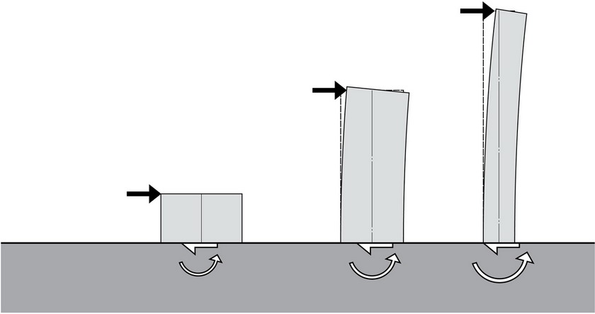
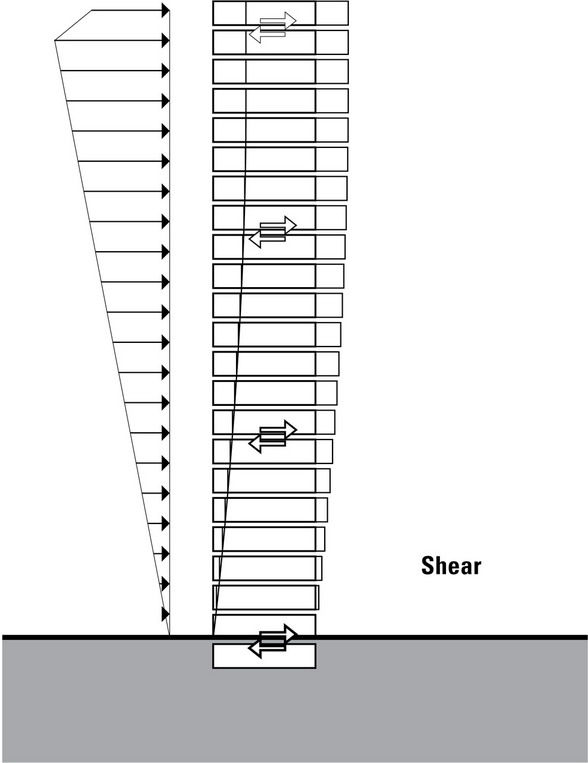
- The effects of lateral forces on a structure increase significantly with its height and slenderness.
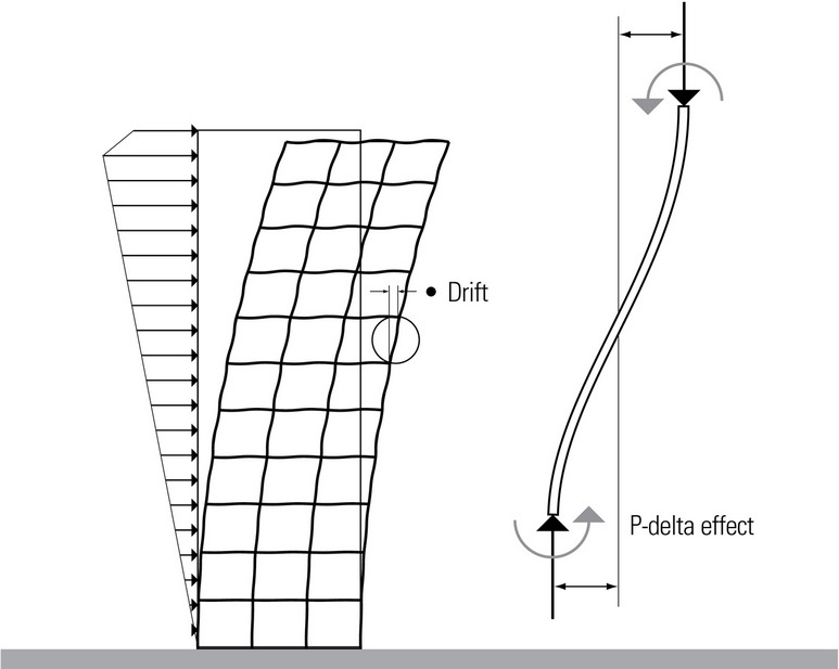
Lateral deflection or drift can become very large as the height of a building increases. Excessive deflections can cause elevators to become misaligned and occupants to have adverse reactions to the movement. The two primary causes of lateral deflections and vibrations are wind load and seismic forces. Another factor that cannot be ignored is the temperature differential, between the inside and outside, and between the sunny and shady sides of a building.
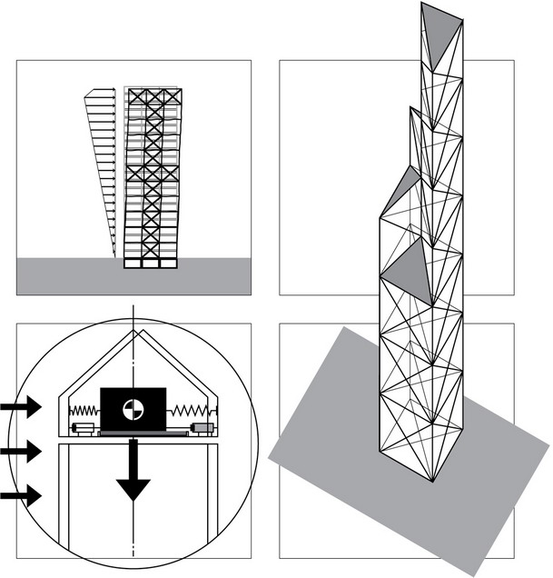
As tall structures are displaced from a true and plumb position, the weight of the structure, displaced from the neutral center position, contributes an additional overturning moment. The magnitude of this additional moment is commonly in the order of 10% of the moment creating the original displacement. This potentially serious phenomenon is known as the P-delta effect.
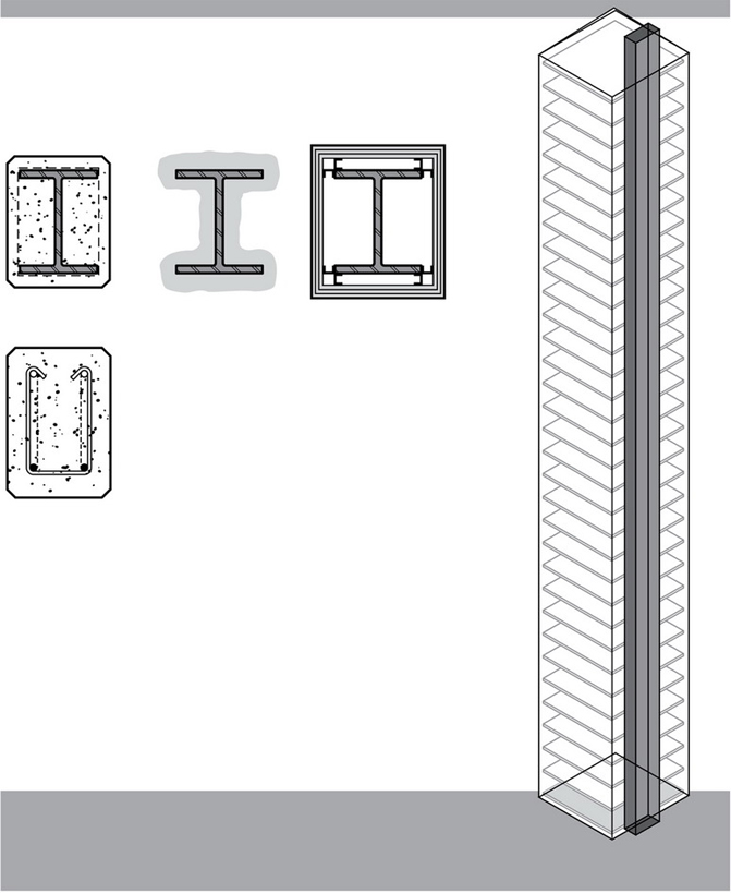
The construction materials for high-rise buildings are varied and are used most often in combination: structural steel, reinforced concrete, and prestressed concrete.
The quantity of structural material required per square foot of floor of a high-rise building exceeds the requirements for low- and medium-rise buildings. The vertical load carrying elements—columns, walls, and shafts—need strengthening over the entire height of the building and the quantity of materials required for lateral load resistance is even more significant.
Since the floor systems in high-rise buildings are typically repetitive in nature, the structural depth of the floor system can have a major impact on the building design. Saving a few inches per floor level can add up to an accumulation of many feet in the building. This will affect the cost of elevators, wall cladding, and other subsystems. Any weight added to the floor systems will also increase the size and cost of the foundation system.
To these supplemental costs must be added the increase in cost of the building services, primarily the vertical transportation system. The cost of the net usable floor area is further increased by the space required for the vertical transportation system, which increases with the height of the building. This increase in size of the vertical transportation core, however, can be used as an important part of the vertical and lateral load-carrying strategy.
FORCES ON HIGH-RISE STRUCTURES
Gravity Loads
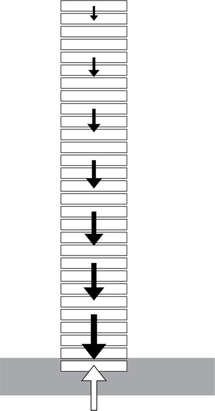
The vertical components carrying the vertical gravity loads of a high-rise structure, such as columns, core shafts, and bearing walls, need to be strengthened over the full height of the building due to the accumulating nature of the loads from the roof level down to the foundation. The quantity of structural materials therefore necessarily increases as the number of stories of a high-rise building increases.
The increase in weight for gravity loads is much greater for concrete than for steel-framed high-rise structures. This increase can be an advantage since the dead weight of the concrete structure assists in resisting the overturning effects of wind forces. On the other hand, the larger mass of a concrete building can be a liability during an earthquake, producing a greater overall lateral force during the seismic event.
In contrast to the vertical gravity-load-carrying elements, which need strengthening, the horizontal spanning floor and roof systems for high-rise structures are similar to those for low- and medium-rise buildings. The spanning members of the floor and roof systems help to tie the vertical structure together and serve as horizontal diaphragms. The most common floor system for steel-framed high-rise structures is corrugated metal decking with a lightweight concrete fill. This provides spaces for the distribution of power and communication wiring as well as small service ducts throughout the floor.
In reinforced concrete high-rise structures, it can be economical to use a framework of beams and girders supporting a lightweight structural concrete slab.
Trussed joists for long-span designs can be economical, even if the floor systems are deeper than normal. The mechanical systems can pass through the open web areas of the joists without any additional floor depth required below the bottom chord of the trusses.
In residential high-rise buildings, a post-tensioned flat slab design is often used for spans not exceeding 25 to 30 feet (7.6 to 9.1 m) with slab thicknesses in the range of 6 to 7 inches (150 to 180) or at most 8 inches (205). The flat slabs are supported directly by columns without any supporting beams, resulting in minimal structural floor depth. However, any mechanical and electrical services would have to be suspended below the slab.
In designing for safety, the aim is to reduce the likelihood of building collapse from wind and seismic forces. Secondarily, consideration must be given to the potential failure of cladding materials, architectural elements, utilities, and services.
Except for high-risk seismic zones, wind is the force that most affects the design of high-rise buildings. Wind loads acting on the overall structure are generally given as stepped increments of wind pressure, increasing in magnitude as the height above ground increases. These wind loads are assumed to act normal to the vertical surfaces of the building, with consideration also given to the effect of quartering wind.
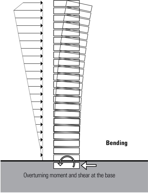
Under a steady wind, a high-rise structure deflects like a vertical cantilever beam that is fixed at the ground level. However, wind gusts on the building can oscillate and the smaller modal deflections can also cause vibrations in the building. Small oscillations may contribute to some occupants feeling uncomfortable and insecure. The inherent stiffness and damping characteristics of most high-rise buildings preclude the possibility of wind-induced resonance and aerodynamic instability.
Seismic movements in a building are different from those produced by wind. Under catastrophic earthquakes, a building will deflect much more and may deflect in random directions, with the challenge of avoiding movements large enough to produce collapse. The critical periods of vibration of earthquakes are generally in the range of fractions of a second while the period for flexible high-rise buildings will be several seconds. When the earthquake period is kept out of phase from the building period, the possibility of harmonic resonance is lessened. Harmonic resonance increases the amplitude of the displacement and can result in catastrophic movement. Tall buildings are designed to be relatively rigid under wind loading but certain parts of the structure may be allowed to yield or crack locally under earthquake loads to lengthen the building’s period of vibration and increase its damping capability. This is done to resist catastrophic failure for very strong earthquakes. The ductility requirement for seismic design involves equipping buildings with reserve strength—through plastic yielding beyond the elastic limit—so that the building can sway without losing its structural integrity.
In multistory structures, lateral loads from wind and earthquakes are distributed to each of the floor or diaphragm levels. At any given floor or roof level, there must be a requisite number of braced or shear walls to transfer the cumulative lateral shear forces from the diaphragms above.
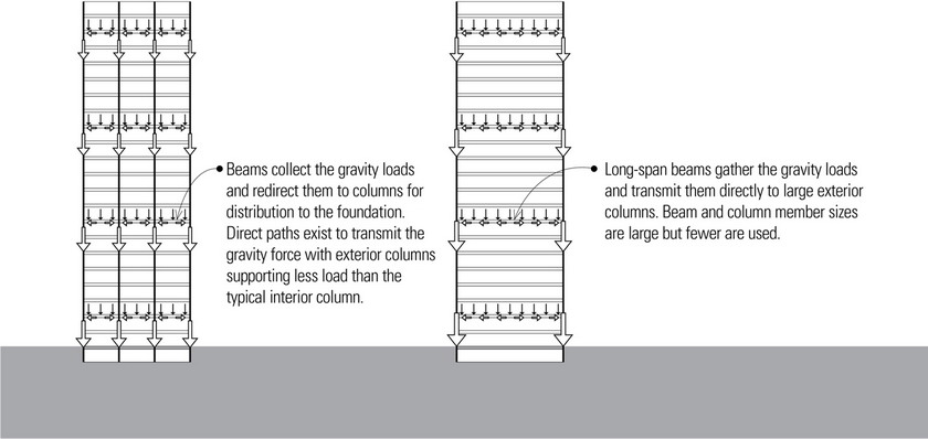
In tall buildings, the overturning moment due to lateral loading is significant. It is advantageous for the floor system to distribute a major part of the gravity load of the building to the exterior resisting elements in order to stabilize them by precompression against tensile overturning force requirements. This can be achieved by eliminating as many interior columns as possible and using long-span floor systems capable of spanning from the central core to the exterior columns. This stronger floor can also make an appropriate contribution to resisting lateral shear forces.
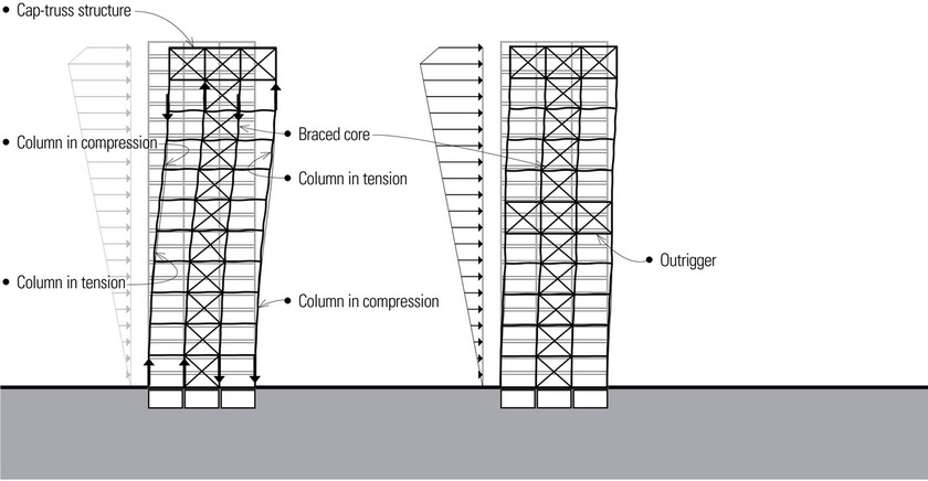
A cap truss or outriggers at the roof level, tied to the core and combined with the exterior tie-down columns, serve to reduce the overturning moment and lateral drift in the building. The tie-downs are attached at every story and support gravity loads in addition to restraining the lateral movement of the frame.
A variation of the cap truss and tie-down concept is the use of outriggers at various levels in the height of the building. The core is often centrally located with outriggers extending on both sides. When the shear core tries to bend, the outriggers act as lever arms that place direct axial loads, tension on one face and compression on the other, into the perimeter columns. These columns, in turn, act as struts to resist the deflection of the core. The outriggers generally are in the form of trusses in steel-frame structures or walls in reinforced concrete structures, or they may be a composite assembly of steel and concrete.
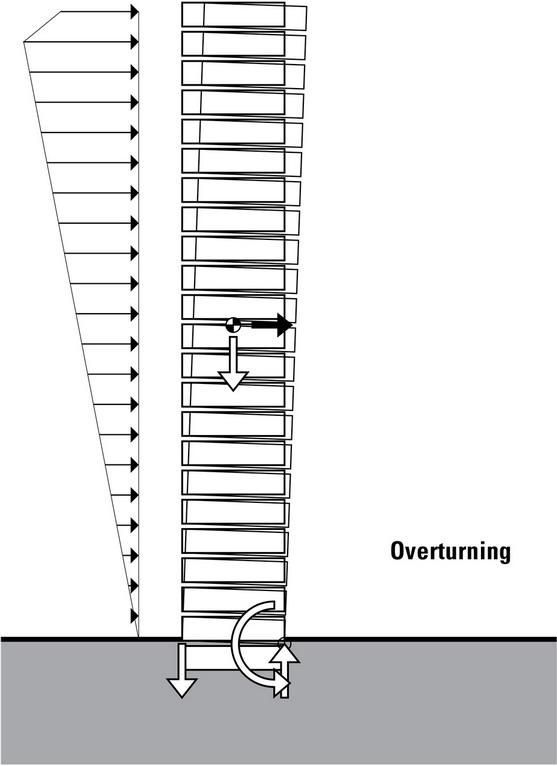
Any lateral load applied at a distance above grade generates an overturning moment at the base of a structure. For equilibrium, the overturning moment must be counterbalanced by an external restoring moment and an internal resisting moment provided by forces developed in column members and shear walls. Tall, slender buildings with a high aspect (height-to-base width) ratio experience larger horizontal deflections at their tops and are especially susceptible to overturning moments.
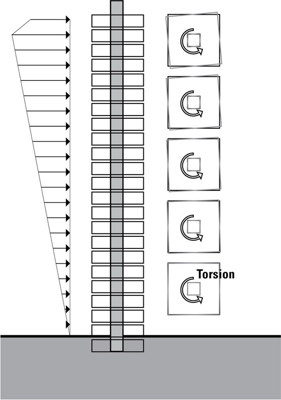
While torsion may be present in buildings of any height, it can be particularly critical in high-rise structures. Due to the extreme height of high-rise buildings, a story torsion that would normally be considered acceptable in low- and midrise buildings can accumulate over many stories to cause a total rotation for the high-rise that would be unacceptable. The motions associated with torsion can add to the swaying motion along the building’s axes, creating unacceptable translations and accelerations.
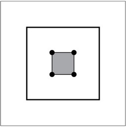
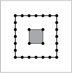
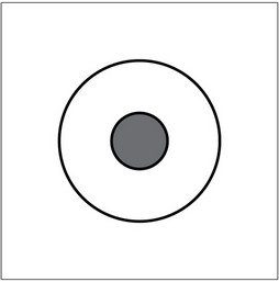
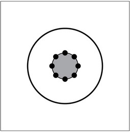
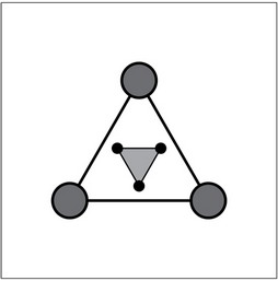
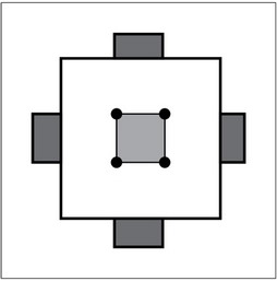
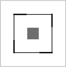
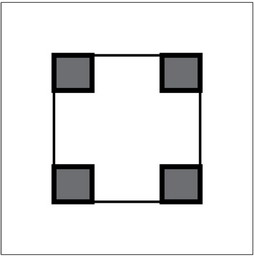
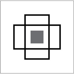
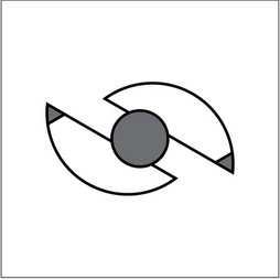
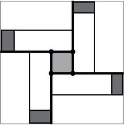
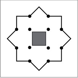
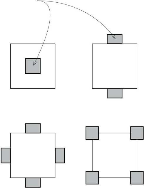
Multistory structures are generally braced with a minimum of four lateral-force-resisting planes per story, each wall being positioned to minimize torsional moments and displacement. Although it is desirable to position the lateral resisting planes in the same position at each floor level, it is not always necessary. The transfer of shear through any one level may be examined as an isolated problem. Torsional resistance is maximized by positioning lateral-force-resisting systems and cores in a balanced, symmetrical manner. This minimizes the possibility of the building’s center of mass being offset or eccentric from its center of rigidity or resistance.
Illustrated on this page are inherently stable plan configurations for high-rise structures. Open forms of bracing are inherently weak in torsional stiffness and should be avoided. L-, T-, and X-shaped plan arrangements are the worst in torsional resistance while C and Z configurations are only slightly better.


TYPES OF HIGH-RISE STRUCTURES
The proper choice of a lateral-force-resisting system can make or break a high-rise project in terms of constructibility, usefulness, and economics.
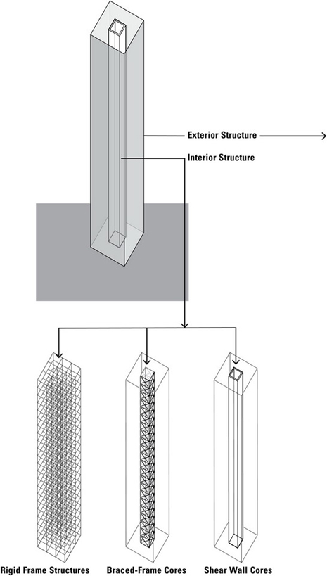
We can divide high-rise structures into two categories, based on the dominant location of the vertical lateral-resisting systems: interior structures and exterior structures.
Interior Structures
Interior structures are high-rise structures that resist lateral loads primarily through lateral-force-resisting elements located within the interior of the structure, such as a rigid frame structure of steel or concrete, or a structure braced by a core consisting of braced frames, moment frames, or shear walls constructed into a closed system that acts as a structural tube.
Exterior Structures
Exterior structures are high-rise structures that resist lateral loads primarily through lateral-force-resisting elements located along the perimeter of the structure.
Braced Frames
Tube Structures
Tube-in-Tube Structures

Diagrid Structures
Trussed Tubes
Bundled Tubes
Space Truss
Megaframe Structures
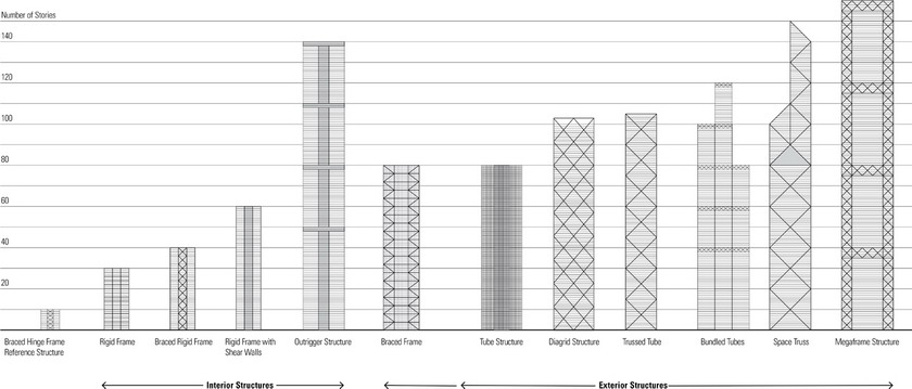
The graph below shows the basic types of high-rise structures and the number of stories each type can reasonably attain.
STABILIZING HIGH-RISE STRUCTURES
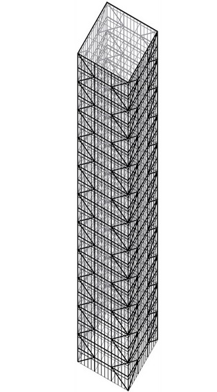
Rigid Frame Structures
One of the primary and predominant structural systems employed for tall steel and concrete buildings through the 1960s was the conventional rigid frame. The structural framework represents a vertical cantilever beam with a fixed base at the ground.
Wind and earthquake loads are assumed to act laterally, generating shear and bending moments in addition to the vertical gravity loads. The floor framing system usually carries almost the same gravity loads at each floor but the girders along the column lines need to be progressively heavier toward the base of the building to resist the increasing lateral forces and to augment the building’s stiffness.
Column sizes increase progressively toward the base of the building due to the accumulated increase in gravity loads transmitted from the floors above. Additionally, the columns toward the base need to be increased further to resist the accumulating lateral loads. The net result is that as a building’s height increases and its sway from lateral forces becomes critical, there is a greater demand placed on the columns and girders that make up the rigid frame system to carry the lateral forces.
In rigid frame construction, the beams and girders spanning in both directions must be stiff enough to minimize the shear-racking or drift of the high-rise floors. This generally requires additional material for the beams and girders unless the floor drift can be controlled by other vertical elements, such as shear walls or structural cores. The quantity of materials required for resisting lateral loads could increase to such a degree that rigid frame systems would become cost-prohibitive for use in buildings exceeding 30 stories in height.
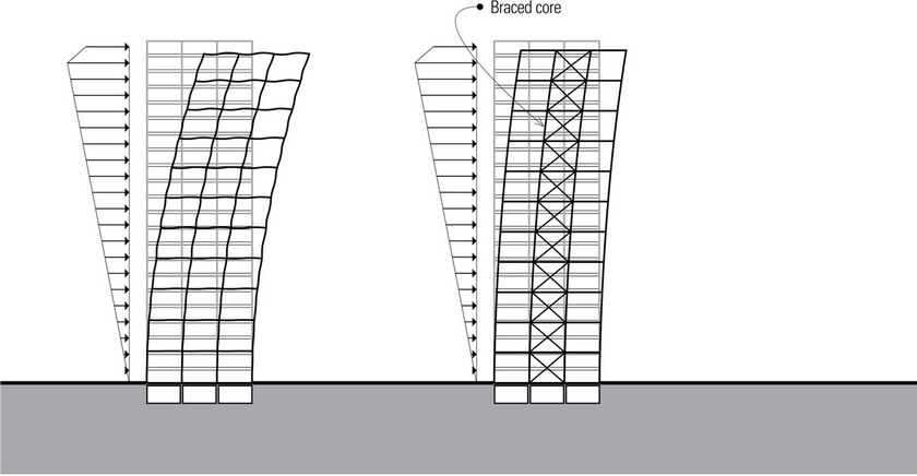
Vertical steel shear trusses or concrete shear walls alone are effective in providing lateral resistance for buildings from 10 to 35 stories high. However, when shear walls or shear trusses are combined with rigid, moment-resisting frames, the interaction of the two lateral-force-resisting systems can produce greater lateral rigidity for the building and increase its capability to rise as high as 60 stories.
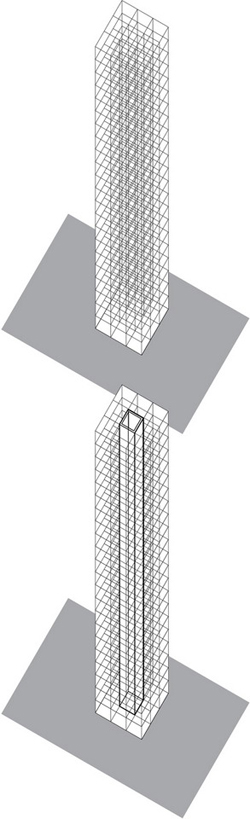
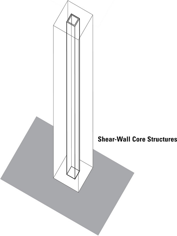
The vertical circulation cores for elevators and emergency egress stairways are usually constructed of reinforced concrete or braced steel frames, enabling them to be used as a major component of the gravity and lateral-force-resisting strategy for multistory buildings. The placement of the shear-resisting core is critical in minimizing the possibility of torsion due to lateral loads. A relatively symmetrical placement of structural cores and braced frames or shear walls can alleviate the eccentricity between the center of mass of a diaphragm level and the center of rigidity or resistance.
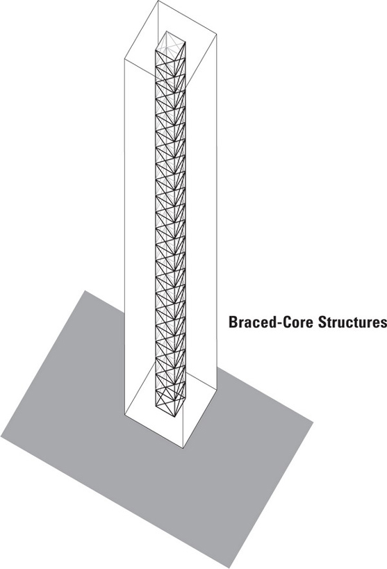
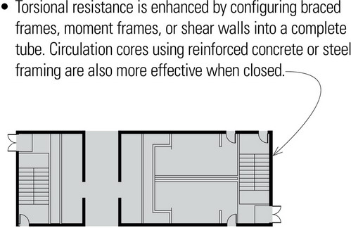
Regardless of core location, the preferred lateral resistance system is of the closed type, with the bracing or frame action forming a complete tube. Examples of this are tubular framed towers with continuous, moment-connected spandrels and columns around the building perimeter; braced cores with the core sides stiffened by diagonals or knee braces; and structural concrete cores with heavily reinforced lintel beams over doorways acting as links between wall segments. These closed forms are preferred because of their inherent torsional stiffness.
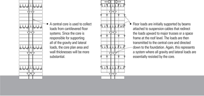
High-rise structures may contain a single or multiple cores. Large single-core structures may support cantilevered floor structures, or be combined with a top-hat structure or intermediate outriggers to provide column-free spaces at each floor level.
Braced Frames
Braced-frame structures use vertical trusses to resist the lateral loads in tall buildings. These vertical trusses use the perimeter columns as chord members and K-, V-, or X-braces as web members, effectively eliminating bending in the columns under lateral loading. The columns, girders, and diagonal bracing can be simply connected with pin joints, making their fabrication and erection more economical than the moment-resisting connections required for rigid frame structures. The diagonal bracing increases the structure’s stiffness, moderates drift, and enables greater overall heights. Braced frames are generally used in conjunction with other lateral-force-resisting systems for taller buildings.
Eccentrically braced frames use diagonal braces that are connected to the floor girders that form horizontal elements of the truss. The eccentricity of the axial offsets introduce bending and shear into the frame, lowering the stiffness of the frame but increasing its ductility, which is an advantage in seismic zones where ductility is an important requirement for structural design. Eccentrically braced frames also have the ability to accommodate wide door and window openings in their plane.
If the diagonal bracing members increase in scale to cross several floor levels, the system falls closer to the category of a megaframe structure.
Shear Walls
Shear wall systems are often used for high-rise structures to provide the necessary strength and stiffness to resist the lateral forces caused by wind and earthquakes. Generally constructed of reinforced concrete, the shear walls are relatively thin and tend to have relatively high (height-to-width) aspect ratios.
Shear walls are treated as vertical cantilevers fixed at their base. When two or more shear walls in the same plane are connected by beams or slabs, as in the case of shear walls with window and door openings, the total stiffness of the system can exceed the sum of the individual wall stiffnesses. This occurs because the connecting beam forces the walls to act as a single unit (like a large rigid frame) by restraining the individual cantilever actions. When designed to act as a unit, the assembly is known as a coupled shear wall.
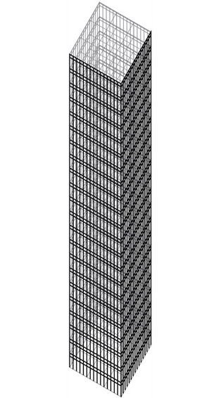
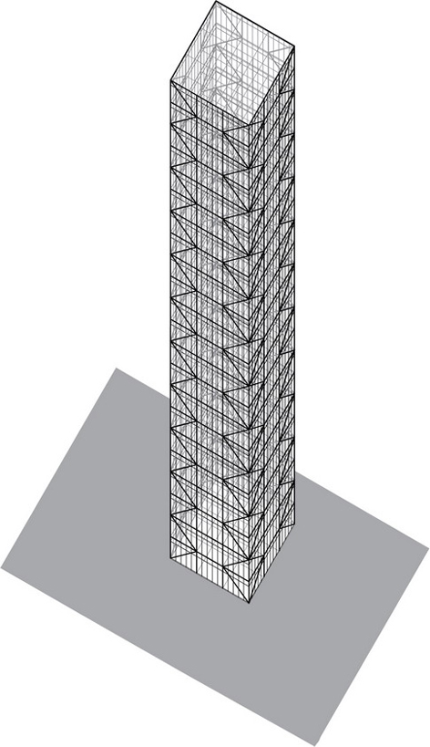
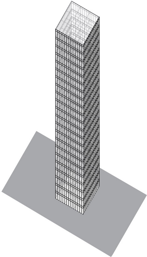
Tube Structures
A framed-tube structure utilizes the entire building perimeter to resist lateral loads. The basic tubular structure is best viewed as a hollow, cantilevered box beam fixed at the ground level, with exterior frames constructed of closely spaced columns rigidly connected to deep spandrel beams. Previous examples of framed-tube systems, like the former World Trade Center Towers, used columns spaced from 4 to 15 feet (1.2 to 4.6 m) on center and spandrel beams from 2 to 4 feet (610 to 1220) deep.
The tube can be rectangular, circular, or other relatively regular shape. Since the exterior walls resist all or most of the lateral loads, much or all of the interior diagonals and shear walls are eliminated. The stiffness of the facade can be further enhanced by adding diagonal braces to create a trussing action.
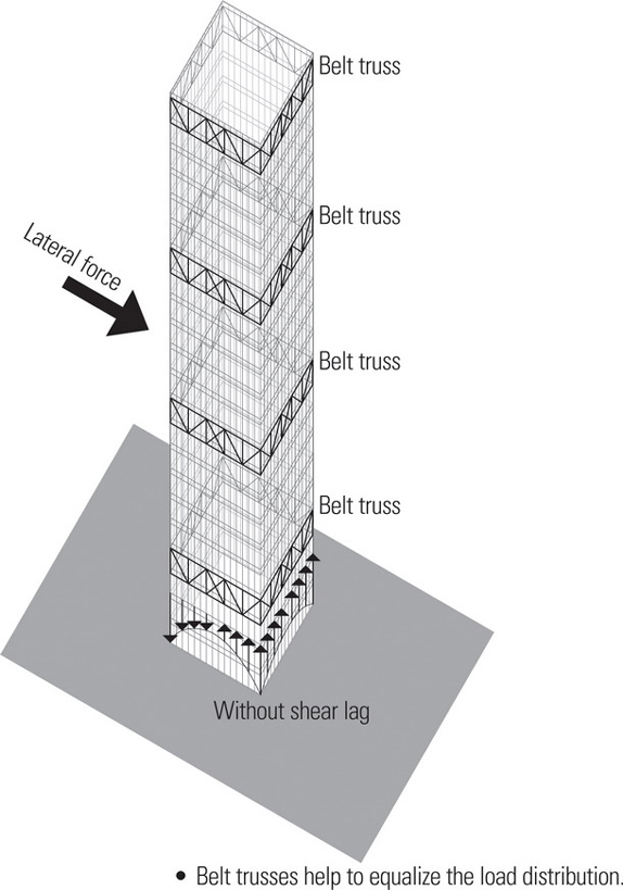
When a building bends as a cantilever beam would under lateral loading, the racking of the structural frame causes an uneven distribution of axial column loads. The corner columns experience larger loads and the distribution is nonlinear from each corner toward the middle. Since the framed tube’s behavior is somewhere between that of a pure cantilever and a pure frame, the sides of the tube parallel to the lateral load tend to act as independent multibay rigid frames due to the flexibility of the columns and spandrel beams. This causes the columns toward the middle of the frames to lag behind those near the corners, unlike the behavior of a true tube. This phenomenon is known as shear lag.
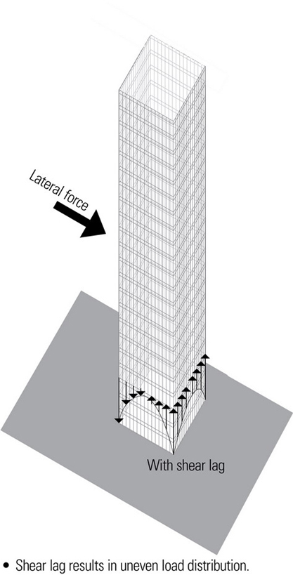
Designers have developed various techniques for reducing the effects of shear lag. Among these, the most notable is the use of belt trusses. Belt trusses are placed on the exterior wall planes, often at mechanical floors, to assist in equalizing the tension and compression forces due to shear lag.
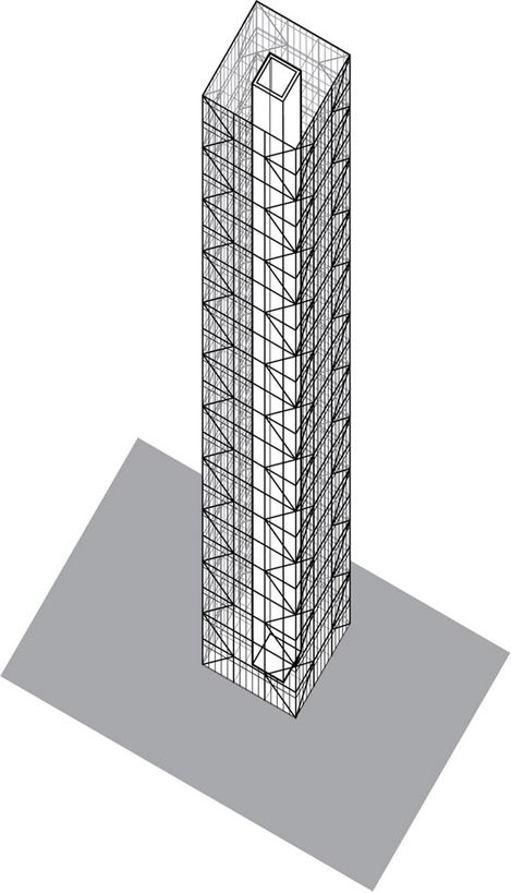
Tube-in-Tube Structures
The stiffness of framed tubes can be improved considerably by using a structural core to not only resist gravity loads but to resist lateral loads as well. The floor diaphragms tie the exterior and interior tubes together, allowing the two tubes to resist lateral forces as a unit. This system is known as a tube-in-tube structure.
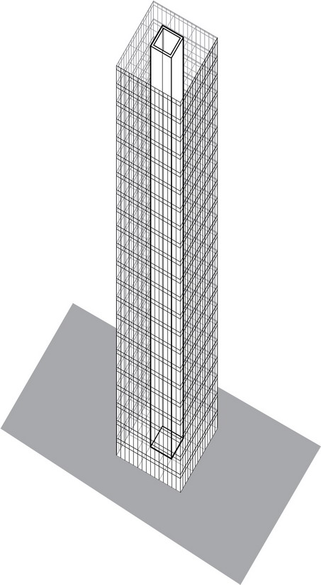
The exterior tube, with its larger plan dimensions, can resist the overturning forces quite efficiently, however, the openings required in this tube compromise its capacity to resist shear, particularly at the lower levels. On the other hand, the solidity of the inner tube, which can be constructed of shear walls, braced frames, or moment frames, can better resist the story shear.
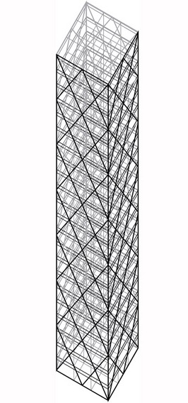
Braced-Tube Structures
An inherent weakness of framed-tube structures lies in the flexibility of their spandrel beams. Framed tubes can be stiffened by adding large diagonals to the exterior wall frame, as at the 100-story John Hancock Center in Chicago. When diagonals are added to a framed-tube structure, it is called a braced-tube structure.
The large diagonal braces together with the spandrel beams create a wall-like rigidity against lateral loads. This stiffening of the perimeter frames overcomes the shear lag problem faced by framed-tube structures. The diagonals support lateral load forces primarily through axial action and also act as inclined columns in resisting gravity floor loads, allowing the exterior columns to be spaced farther apart.
Bundled-Tube Structures
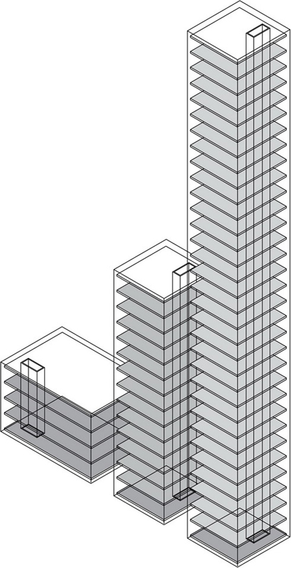
A bundled-tube structure is a cluster of individual tubes tied together to act as a single unit. Single framed tubes are restricted in height by their slenderness (height-to-width ratio). Combining several tubes to act in unison with each other adds considerably to their stiffness and moderates the sway at the upper floors. A special weakness of this system is the differential column shortening.
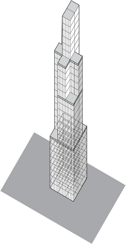
Chicago’s 110-story Sears Tower, designed by SOM, consists of nine framed steel tubes, each with its own structural integrity. Because each of the individual tubes are independently strong with respect to wind load, they can be bundled into varying configurations and terminated at various levels. Only two of the modules rise to the full 1450-foot (440-meter) height of the structure. Two drop off at the 50th floor, two more at the 66th, and three at the 90th. Dropping off modules reduces wind sway by breaking the flow of the wind. The nine modules are each 75 by 75 feet (22 by 22 meters) square and have common interior columns that make up two diaphragms trisecting the building in two directions and thereby stiffening the structure. The interior diaphragms act as webs of a huge cantilever beam in resisting shear forces, thus minimizing shear lag.
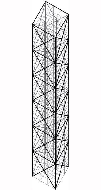
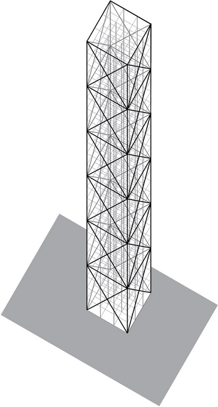
Space-Truss Structures
A space-truss structure is a modified braced tube based on the idea of stacking triangulated prisms which contain diagonals connecting the exterior with the interior frame. The space truss resists both lateral and vertical loads. Unlike the more typical braced-tube structure with diagonals placed on the exterior wall planes, the space-truss system introduces diagonals that become an integral part of the interior space.
A prominent example of a space-truss system is the 72-story Bank of China Building in Hong Kong, designed by I.M. Pei, consisting of triangular prisms of different heights, which transfers internal loads to the building corners at 13-story intervals. The space truss resists the lateral loads and transfers almost the entire weight of the building onto the four super-columns at the corners.
Megaframe Structures
As buildings rise above the 60-story range, megaframe or superframe structures become a viable possibility. Megaframe structures use megacolumns comprising the chords of oversized braced frames at the building corners, which are linked by multistory trusses at 15- to 20-story intervals; these are often the mechanical floor levels. The entire story depth of the mechanical floors can be used to construct a strong and stiff horizontal subsystem. Linking these very large girders or space trusses to the megacolumns produces a rigid megaframe that can be infilled with a lighter secondary frame of standard design.
Diagrid Structures
A fairly recent application of a lattice-like framework on the exterior surface of the building to resist both lateral and gravity loads is the diagrid (diagonal grid) system. Diagrid structures differ from conventional braced frames in their ability to resist gravity loads, which is so effective that vertical columns are virtually eliminated.
The diagonal members in the diagrid system carry both gravity and lateral loads through triangulation, which results in a relatively uniform load distribution. Shear deformation is minimized very effectively because the diagonals resist the shear through axial action rather than by bending of vertical columns and horizontal spandrels. Diagrids provide both shear and bending rigidity to resist the effects of drift and overturning moment. Diagrid systems are also highly redundant and can transfer loads through multiple paths in case of a localized structural failure. See page 186.
The most common structural material used in diagrids is steel. Because of their structural efficiency, diagrids generally require less steel than other types of high-rise structures.
- The diagrid structural system can accommodate a variety of open floor plans. Beside the service core, the typical floor plan can be free of columns and other structural elements.
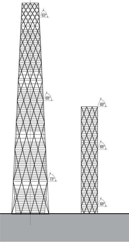
- Design studies indicate that using variable-angle diagrids for very tall buildings with height:width aspect ratios over 7 results in structural efficiency. However, using uniform-angle diagrids for buildings with height:width ratios lower than 7 reduces the amount of steel required.
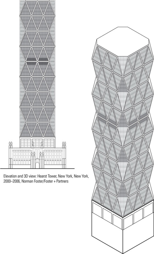
The Hearst Tower has 46 stories, stands 597 feet (182 m) tall, and contains 860,000 sf (80,000 m2) of office space. Because the triangulated three-dimensional form of the steel diagrid structure is capable of both supporting gravity loads and resisting lateral wind forces, there is no need for exterior vertical columns. The diagrid structure reportedly used 20% less steel than a conventionally framed high-rise of similar size.
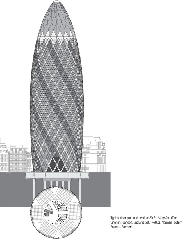
30 St. Mary Axe—informally known as The Gherkin and previously, the Swiss Re Building—is a skyscraper in London’s financial district. With 41 floors, the tower is 591 feet (180 m) tall and stands on the site of the former Baltic Exchange, which was extensively damaged in 1992 by the explosion of a bomb placed by the Provisional IRA. After plans to build the Millennium Tower were dropped, 30 St. Mary Axe was erected, soon becoming an iconic symbol of London and one of the city’s more widely recognized examples of modern architecture.
The shape of the tower was partially influenced by the need to have a smooth flow of wind around the building and minimize its impact on the local wind environment. Across this curved surface the diagrid structure is formed by generating a pattern of intersecting diagonals spiraling in two directions.
The unusual geometry of the tower gives rise to significant horizontal forces at each node level where the diagonal columns intersect, which are resisted by perimeter hoops. As with dome structures, the hoops in the upper region are in compression while those at the middle and lower levels are subject to significant tensile forces. The hoops also serve to transform the diagrid into a very stiff triangulated shell, freeing the interior core from the need to resist lateral wind forces. Foundation loads are also reduced when compared with a high-rise structure stabilized by its core.
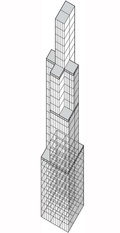
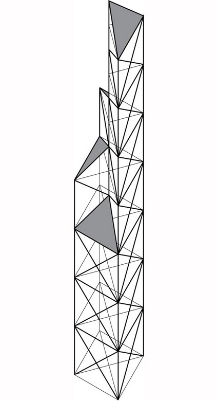
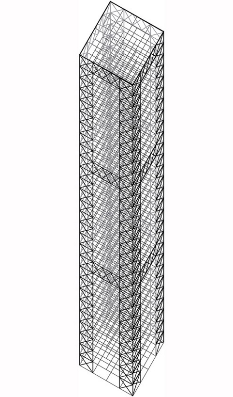
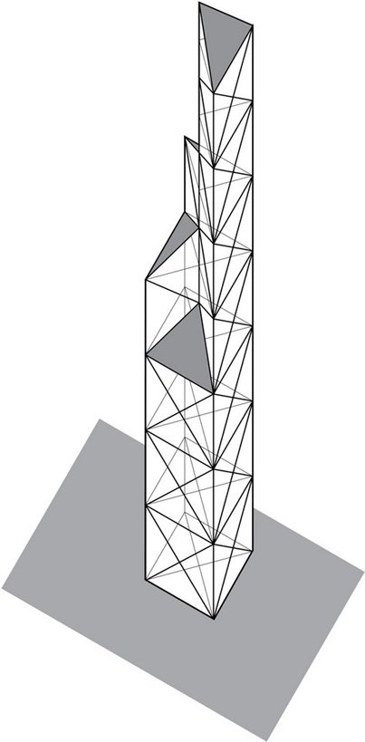
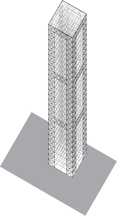
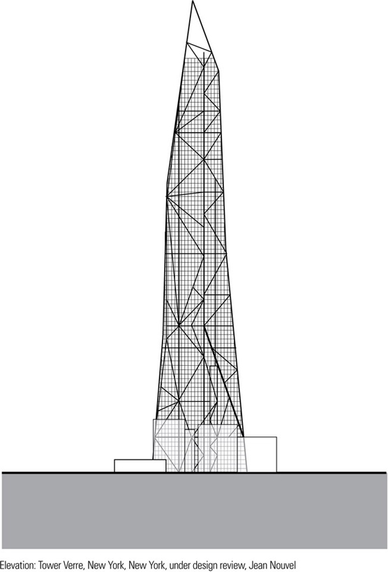
This elevation represents the most recent redesign of Tower Verre—a slender, 75-story steel-framed skyscraper that is shorter than the originally planned 1050-foot (320-m), 78 story high-rise. As opposed to the regular geometry of both the Hearst Tower and St. Mary Axe, Tower Verre uses an irregular diagrid structure to compose its faceted exterior that tapers to a set of three distinct asymmetrical, crystalline peaks at the apex of the tower.
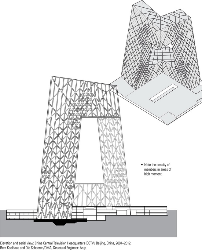
The China Central Television (CCTV) Headquarters is a 768-foot (234-m)-tall skyscraper in the Beijing Central Business District. Groundbreaking took place on June 1, 2004 and the building’s facade was completed in January 2008. After construction was delayed by a fire in February 2009 which engulfed the adjacent Television Cultural Center, the CCTV Headquarters building was finally completed in May 2012.
To resist the large moment and corresponding forces generated by the two towers—each inclined 6° in two directions—as well as significant potential seismic and wind events, ARUP engineers developed a system whereby vertical interior columns and elevator shafts along with inclined exterior columns carry vertical loads while diagonals provide lateral bracing and form a rigid tube truss across the building surfaces similar to a diagrid structure. This web of diagonal steel braces expresses the distribution of forces that the structure experiences under different load conditions. Where structural forces are greater, the web of diagonals is denser; where the forces are less intense, the web is looser.
The distinctive double cantilever of the CCTV Headquarters building consists of a multistory bridge above the 37th story of the two towers, extending 220 feet (67 m) in one direction and 245 feet (75 m) in the other.
DAMPING MECHANISMS
Although stiffening a tall structure to reduce sway and limit deflections and deformation under lateral loading, large increases in structural size relative to those required for strength alone are often required to achieve satisfactory dynamic performance. A more cost-effective approach is to use damping systems that mitigate the effects of wind-induced vibration and earthquake shaking on tall structures, as well as on its nonstructural architectural elements and mechanical components. By absorbing and dissipating a significant portion of the energy transmitted to the building during high winds or a seismic event, damping systems limit excessive motion and deflections, moderate structural member sizes, and add to occupants’ comfort level against sway perception.
The base isolation system described in Chapter 5 is an effective damping system for stiff buildings up to seven stories in height. For taller buildings subject to overturning, there are three types of damping systems used to control excessive motions and deflections and ensure occupancy comfort. These are active damping systems, passive damping systems, and aerodynamic damping.
Active Damping Systems
Damping systems that require power for motors, sensors, and computer controls are known as active systems; those that do not are passive systems. The most significant drawback to active damping systems is that external power is required to regulate their movement and may be undependable during a seismic event when the power supply could be disrupted. For this reason, actively controlled dampers are more suitable for tall buildings subject to wind-induced loading rather than the more unpredictable cyclic loading caused by earthquakes.
Semi-active damping systems combine the features of passive and active damping systems. Rather than push on a building’s structure, they use a controlled resistive force to reduce motion. They are fully controllable yet require little input power.
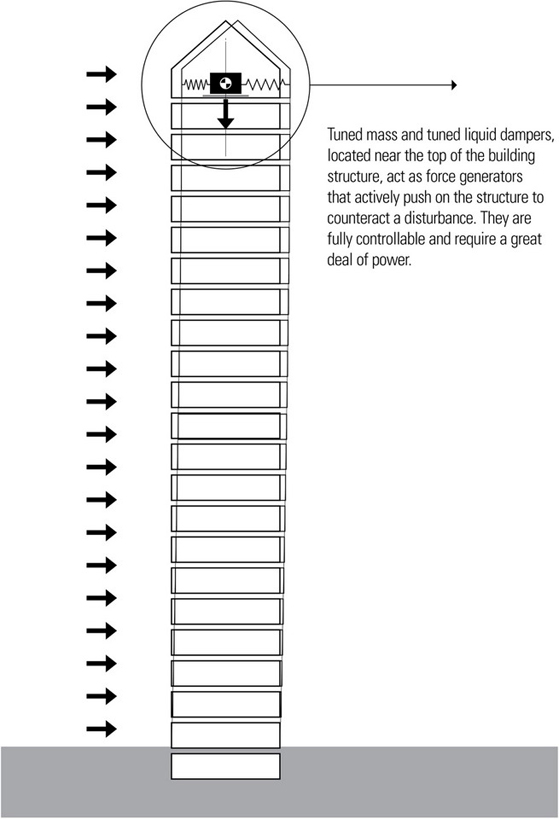
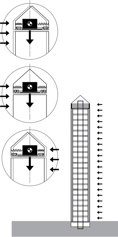
Tuned mass dampers are active systems that consist of a large mass of concrete or steel suspended from a cable like a pendulum or mounted on tracks in the upper stories of a building. When lateral forces produce swaying in the building, a computer senses the motion and signals a motor to move the weight in an opposing direction to minimize or neutralize the motion. Tuned mass dampers use very carefully determined weights that take into account the building’s weight, the location of the mass in the building, the lag time, and the mode of motion that is to be counteracted. Tuned mass dampers are very useful in reducing building sway during wind storms but are less satisfactory for controlling building deflections during seismic events.
Tuned liquid dampers use water or other liquid in a tank designed to give the desired natural frequency of water motion. When the building moves under wind loading, the water in the tank moves back and forth in the opposing direction, transferring its momentum to the building and counteracting the effects of the wind vibration. A benefit of using a tuned liquid damping system is the availability of the water in the tank for firefighting.
An active tendon damping system uses a computerized controller that responds to building movement by actuating tension-adjusting members which are connected to an array of steel tendons disposed adjacent to the structure’s main support members. The tension-adjusting members apply tensile force to the tendons to counter the force causing the deflection of the structure and dampening the oscillation of the structure. Active pulse systems use hydraulic pistons in the foundation or between the stories of a building to significantly reduce the lateral forces acting on a structure. Both active and tendon systems can also be used to counteract the effects of torsion by being placed off center in the structure.
Passive Damping Systems
Passive damping systems are incorporated within a structure to absorb a portion of the wind-induced or seismic energy, reducing the need for primary structural elements to dissipate energy. There are a number of manufactured dampers available, using a variety of materials to obtain different levels of stiffness and damping. Some of these include viscoelastic, viscous fluid, friction, and metallic-yield dampers.
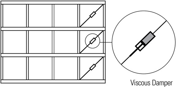
Viscoelastic and viscous dampers act as large shock absorbers to dissipate energy over a broad range of frequencies. They can be designed for integration into structural components and connections to control both wind and seismic responses in tall buildings.
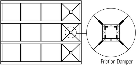
Friction dampers dissipate energy only when the slip force of two surfaces rubbing against each other is reached and exceeded. Metallic-yield dampers dissipate energy through the inelastic deformation of the material. Both friction and metallic-yield dampers are developed for earthquake engineering applications and are unsuitable for mitigating wind-induced motion.
Aerodynamic Damping
The wind-induced motion of tall buildings has primarily three modes of action: drag (along with the wind), cross-wind (transverse to the wind direction), and torsion. Of these, cross-wind pressures alternating between the two walls of a building parallel to the wind direction, caused by vortex shedding, can induce transverse vibrations large enough to affect the occupants’ comfort.

Aerodynamic damping refers to how buildings can be shaped to affect the airflow around it, modify the pressures acting on its surfaces, and mitigate resulting motion of the structure. In general, objects having the smoothest aerodynamic shape, such as a circular plan building, will impede the airflow much less than a comparable structure with a rectangular plan, resulting in a lessening of the wind effect. Because wind-induced forces become greater with building elevation, the aerodynamic shaping of a high-rise building is one approach which can be used to improve its performance against wind loading and motion. These modifications include rounded and tapered plan sections, setbacks, sculpted tops, modified corner geometry, and the addition of openings through the building.