44
Create an Ultrasonic Speed Detector
JOE STEWART, JAMES BETTKE, ANNIE STEWART, AND SHANE MANN
SubProto
Type of Library Best Suited for: Any
Cost Estimate: $30–$50 each
Makerspace Necessary? Yes
PROJECT DESCRIPTION
If you’ve ever wanted to know how fast fellow librarians are going when they’re racing their book carts through the stacks, then this is the project for you!
The ultrasonic speed detector uses ultrasonic sound to measure speed. The project is intended to be an affordable exercise that will introduce participants to the worlds of electronics, software development, computer-aided design (CAD), and 3D printing. This is a great advanced workshop for more experienced makers to create something extraordinary. Although this may sound daunting, we have done all the hard work for you. All you have to do is follow the instructions and put it all together!
OVERVIEW
The ultrasonic speed detector measures speed. To do so, it must first measure two distances. The first distance is how far it is to an object. The radar waits 50 milliseconds (that’s 50 thousandths of a second!) and then performs another distance measurement. If the object is moving, there will be a difference in the two measurements. That information, combined with the amount of time taken between measurements, can be used to calculate how fast an object is moving.
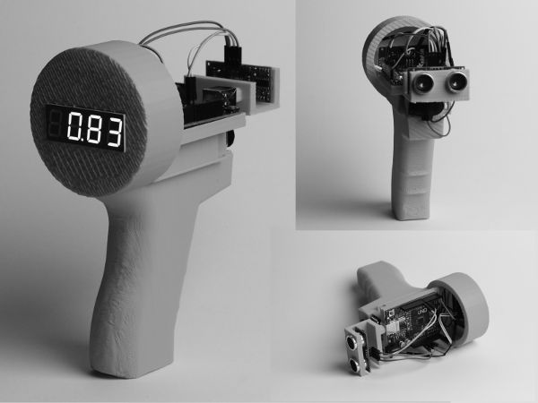
Ultrasonic speed detector
In essence, this is like a radar gun except for one key difference. A radar gun uses the Doppler shift of reflected radio waves. The ultrasonic speed detector uses successive distance measurements to a moving object to calculate that object’s speed.
MATERIALS LIST
- ◦ Project files—download at http://subproto.com/ultrasonic.zip
- ◦ Arduino Uno rev 3 or equivalent
- ◦ Adafruit 0.56” 7-segment LED HT16K33 Backpack
- ◦ HC-SR04 Ultrasonic Distance Sensor Module
- ◦ 9-volt battery
- ◦ 9-volt battery clip/snap connector
- ◦ 8 jumper wires, male to female
- ◦ One W jumper wire, male female male (see picture of red wire with three ends)
NECESSARY EQUIPMENT
- ◦ 3D printer
- ◦ 3D printer software such as Cura or Simplify3D
STEP-BY-STEP INSTRUCTIONS
To begin, download all the files from http://subproto.com/ultrasonic.zip.
3D Print the Frame
- 1. If you don’t have a 3D printer, search your community for a makerspace. A makerspace will surely have a 3D printer you could use to print the frame of your snazzy ultrasonic speed detector.
- 2. Load Cura, Simplify3D, or your favorite 3D printer software.
- 3. It may depend on which 3D printer software you have, but each will offer some way to load a model, usually under File -> Load or similar. Locate the right option and load the file “ultrasonicx.stl” from the files you downloaded.
- 4. Make sure you have configured the 3D printer properly for the type of material you’re using before you begin your print. If you aren’t sure, ask your local makerspace for help.
- 5. Once you’ve kicked off the 3D print for the frame, you can start working on the electronics.
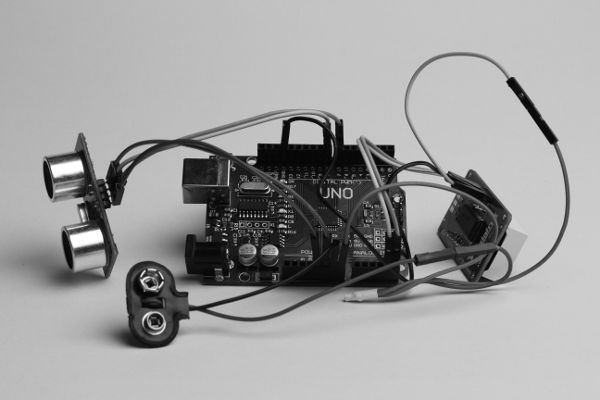
Parts List, Top Right: HC-SR04 Ultrasonic Distance Sensor Module, Right Middle: Arduino Rev 3, Right Bottom: Adafruit 0.56” 7-segment LED HT16K33 Backpack

All wired and ready to go!
Electronics
- 1. Make sure you have all the required parts first.
- 2. Lay out all the parts on a nonmetallic surface. Why yes, you are right, a breadboard would be a great tool for this project!
Connect the HC-SR04 Ultrasonic Sensor to the Arduino
- 1. Use one male-to-female jumper wire to connect pin 7 of the Arduino to the pin labeled “Trig” on the HC-SR04.
- 2. Use one male-to-female jumper wire to connect pin 8 of the Arduino to the pin labeled “Echo” on the HC-SR04.
- 3. Use one male-to-female jumper wire to connect the 5V output pin of the Arduino to the pin labeled “VCC” on the HC-SR04.
- 4. Use one male-to-female jumper wire to connect a GND pin (GROUND) of the Arduino to the pin labeled GND on the HC-SR04.
- 5. The HC-SR04 is now connected to the Arduino!
Connect the Seven-Segment LED Backpack to the Arduino
- 1. Connect one male-to-female jumper wire to a free GND pin of the Arduino and the GND pin of the LED backpack.
- 2. Connect one male-to-female jumper wire to pin A4 on the Arduino and to pin SDL on the LED backpack.
- 3. Connect one male-to-female jumper wire to pin A5 on the Arduino and to pin SCL on the LED backpack.
- 4. The LED backpack is now wired to the Arduino!
Hook Up Your 9-Volt Battery Connector
- 1. Connect the red wire (positive lead) of the 9-volt snap connector to the female lead of the W jumper wire. Plug one male end of the W jumper wire to the VIN pin of the Arduino. Plug one male end of the W jumper wire to a female-to-female jumper wire that is connected to the VCC pin of the LED backpack.
- 2. Connect the black wire (negative lead) of the 9-volt snap connector to the last free GND pin of the Arduino.
- 3. Congratulations, you are all done with wiring!
Load the Software onto the Arduino
- 1. Open your Arduino IDE and import the file “main.cpp.” Arduino IDE will likely ask to create a new project folder. Click yes.
- 2. Use the library manager to add the following libraries to the project:
- a. Wire
- b. Adafruit LED Backpack
- c. Adafruit GFX
- d. NewPing
- 3. Verify that the code compiles.
- 4. Plug the Arduino into your computer.
- 5. Upload the code to the Arduino by pressing the upload button in the Arduino IDE.
- 6. Plug in the 9-volt battery to the 9-volt battery snap connector. The LED backpack should be displaying numbers at this point. If not, make sure all your wire connections are good, or try resetting the Arduino.
- 7. Is your speed detector 3D-printed frame done printing yet? If everything is working, you are ready to mount the electronics into the 3D-printed frame.
Once you’ve mounted the electronics into the frame and attached a battery, you are ready to measure speed. Just aim the detector head-on in the direction of the moving object to be measured and wait for your reading.
LEARNING OUTCOMES
Through this project, makers will . . .
- ◦ Learn about an electronics prototyping platform called Arduino. This includes basic Arduino operation, how to write code to control one, and how to upload that code to one.
- ◦ Learn how 3D printing utilizes computer-aided design models to make physical copies of virtual objects.
RECOMMENDED NEXT PROJECTS
The ultrasonic speed detector is by no means the perfect, final version of this project. As an exercise for the maker, consider refining or improving the project, perhaps with a trigger to start measurement or with a memory to store speeds.